
Related Manuals for Interlogix ATS1745


Summary of Contents for Interlogix ATS1745
-
Page 1: Setup Guide
ATS1745 Advisor Master IP Bus adaptor installation & Setup Guide P/N XXXXXXX (EN) • REV A • ISS 29JUL15 Preliminary manual, not for sales... - Page 2 Copyright © 2015 UTC Fire & Security Americas Corporation, Inc. All rights reserved. Trademarks and Interlogix, Advisor Master name and logo are trademarks of patents UTC Fire & Security. Other trade names used in this document may be trademarks or registered trademarks of the manufacturers or vendors of the respective products.
-
Page 3: Table Of Contents
High latency faults 14 Checking network performance 14 Problems viewing ATS1745 Web pages 16 Problems logging in 17 Resetting the ATS1745 module 17 Network assignments worksheet 18 ATS1745 Advisor Master IP Bus adaptor installation & Setup Guide Preliminary manual, not for sales... -
Page 4: Important Information
OF THE USE OF THIS SOFTWARE, EVEN IF ADVISED OF THE terms. Do not install or use ATS1745 Advisor Master IP Bus Adaptor modules POSSIBILITY OF SUCH DAMAGE. - Page 5 1. Redistributions of source code must retain the above copyright notice, 29K Support Products this list of conditions and the following disclaimer. Mail Stop 573 ATS1745 Advisor Master IP Bus adaptor installation & Setup Guide Preliminary manual, not for sales...
- Page 6 WITH REGARD TO THIS SOFTWARE. IN NO EVENT SHALL SUPERH BE LIABLE FOR INDIRECT, SPECIAL, INCIDENTAL OR CONSEQUENTIAL Copyright (c) 1997-2002 FreeBSD Project. All rights reserved. ATS1745 Advisor Master IP Bus adaptor installation & Setup Guide Preliminary manual, not for sales...
- Page 7 Redistribution and use in source and binary forms is permitted provided that the above copyright notice and following paragraph are duplicated in all (26) Mike Barcroft such forms. ATS1745 Advisor Master IP Bus adaptor installation & Setup Guide Preliminary manual, not for sales...
- Page 8 Rights transferred to Franklin Electronic Publishers. Redistribution and use in source and binary forms, with or without modification, are permitted provided that the following conditions are met: viii ATS1745 Advisor Master IP Bus adaptor installation & Setup Guide Preliminary manual, not for sales...
-
Page 9: Product Overview
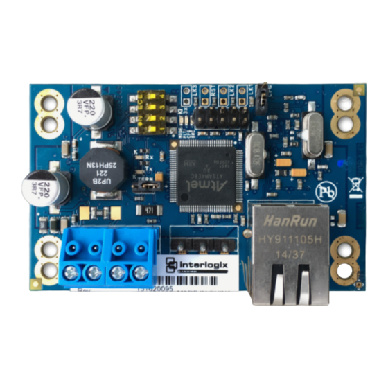
ELM) and can have up to 32 modules (one SLM and 31 ELMs). Figure 1 below and Figure 2 on page 2 depict a pair of ATS1745 modules used to communicate with Bus devices over the IP network. Figure 3 on page 2 depicts one SLM and multiple ELMs. - Page 10 Master Figure 3: One SLM used with multiple ELMs Master Refer to Figure 4 below and this section for details about setting up an ATS1745 module. Figure 4: ATS1745 Advisor Master IP Bus Adaptor general layout (4) (5)
-
Page 11: Led Indications
Mode LED (top) Single flash repeating ELM mode (SW1 OFF) (twice per second) Fault LED (middle) Single flash repeating The ELM cannot communicate with its paired SLM ATS1745 Advisor Master IP Bus adaptor installation & Setup Guide Preliminary, not for sales... -
Page 12: Dip Switch
ATS1745 modules have an onboard Web interface that is used by installers to configure parameters such as assigned IP addresses. For security purposes, an ATS1745 module’s Web server can be locked via SW3 to prevent unauthorized access. See “Using the ATS1745 Web interface” on page 11 for details. -
Page 13: Installation
Note: Before installing, ensure that the CFG pins (Figure 4 on page 2, item 9) are not linked. The CFG pins are linked only to reset an ATS1745 module to its default setting (see “Resetting the ATS1745 module” on page 17). -
Page 14: Connecting The Ats1745 Module
Bus earth terminal. Powering the module The ATS1745 module consumes 100 mA @ 13.8 V, and may be powered from the Advisor Master panel’s or Four-Door Controller’s Bus at J11, or from an external power supply. -
Page 15: System Setup
“DIP switch” on page 4. For security purposes, a module’s Web server can be locked to prevent unauthorized access. Requirements Setting up ATS1745 modules (one SLM and one or more ELMs) requires that you know the following values for each module, as assigned by the network administrator: ... -
Page 16: Programming Assigned Network Parameters
ELM with the assigned network parameters for both the SLM and the ELM. To program the SLM’s assigned network parameters: 1. Select the ATS1745 module with SW1 in the ON position (Figure 4, item 7, on page 2). 2. Connect power and Ethernet cables to the module (Figure 4 on page 2). -
Page 17: Enabling Communications
(Figure 8 on page 12). A green LED to the right of the address indicates encrypted communications. Updating firmware An ATS1745 module’s firmware may be updated from time to time. Refer to the version number displayed below the Logout button on the Web interface (Figure 8 on page 12) for the currently-loaded firmware version. - Page 18 11. Connect power to the module. 12. View the module’s Web interface (Figure 8 on page 12) and note the currently-loaded firmware version. It should display the updated version number. ATS1745 Advisor Master IP Bus adaptor installation & Setup Guide Preliminary, not for sales...
-
Page 19: Using The Ats1745 Web Interface
After logging in, you will see a Device Configuration window, which varies depending on the ATS1745 module’s role (Figure 8 on page 12). The ATS1745 module’s role is determined by the setting of SW1 (Figure 4, item 7, on page 2). -
Page 20: Configuring Devices
Figure 8: Device Configuration windows for SLM and ELM Configuring devices The Device Configuration window varies depending on the ATS1745 module’s role (Figure 8 above). Use the SLM Device Configuration window to: Program the SLM’s assigned network parameters under the Host heading. -
Page 21: Managing Users
An additional four user name and password combinations can be added. All users have the same permissions (the “admin” user does not have special privileges). If an ATS1745 module is reset, the default user named “admin” with password “password” is restored and all other users are deleted. See “Resetting the ATS1745 module”... -
Page 22: Troubleshooting
The corresponding right-hand LED indicator in the Device Configuration window (Figure 8 on page 12) is red, and the message is “Slow”. The ATS1745 module’s onboard fault LED indicates a repeating double flash (see Figure 4, item 8, on page 2). - Page 23 The Advisor Master IP Bus Adaptor Network Tester measures the performance of your network, and estimates the number of poll errors that ATS1745 modules could experience if installed on the network. We recommend that you test the performance across each router that you pbus to use to carry Advisor Master system data for at least 24 hours to ensure that you have tested during peak network load.
-
Page 24: Problems Viewing Ats1745 Web Pages
See “Setting up the installation computer” below. Setting up the installation computer ATS1745 modules are programmed using Internet Explorer to display the Web pages generated by the module’s embedded Web server at either the default IP address or the assigned IP address (provided by the local network administrator). -
Page 25: Problems Logging In
“hard” refresh of the Web browser. This bypasses any cached versions of the window and displays the current window being served by the ATS1745 module. To hard refresh the Web browser, simultaneously press the Ctrl and F5 keys. -
Page 27: Network Assignments Worksheet
Network assignments worksheet Copy this form as needed to list the assigned network details for ATS1745 Advisor Master IP Bus Adaptor modules. Role IP Address Gateway address Netmask Port number ELM1 ELM2 ELM3 ELM4 ELM5 ELM6 ELM7 ELM8 ELM9 ELM10...
Need help?
Do you have a question about the ATS1745 and is the answer not in the manual?
Questions and answers