
Related Manuals for Parker Sporlan IB-G

Summary of Contents for Parker Sporlan IB-G
- Page 1 August 2016 / Bulletin 100-50-2.1 Bulletin 100-50-2.1 – Page 1 Sporlan IB-G Interface Board Installation and Operation Instructions...
-
Page 2: Table Of Contents
The user must analyze all aspects of the application, follow applicable industry standards, and follow the information concerning the product in the current product catalog and in any other materials provided from Parker or its subsidiaries or authorized distributors. -
Page 3: Installation
Bulletin 100-50-2.1 – Page 3 Warning: Do not apply power to the IB-G until wiring is complete. Remove power before making any wiring changes. *Voltage drop must be considered when locating the IB-G away from the power supply and external controller. Digital inputs connected to terminals “OPN”, “CLS”... -
Page 4: Setup
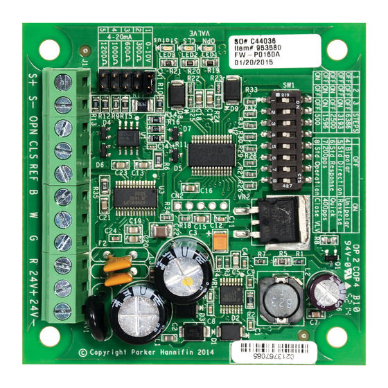
Page 4 – Bulletin 100-50-2.1 2. Setup See Figure 2 for locations of input configurations and DIP switches. With the IB-G unpowered, select the input signal of 0-10V or 4-20mA and desired impedance by installing the supplied jumper to one of the 5 pin locations listed in Table 1. Set the DIP switches in accordance with the valve and desired operation listed in Table 2 and Table 3. -
Page 5: Troubleshooting
Bulletin 100-50-2.1 – Page 5 DIP Switch Settings (Table 3): To force the valve shut during operation for test purposes, turn switch 8 to the “ON” position. To resume normal operation, The IB-G has a DIP switch table that accommodates systems turn switch 8 “OFF”. - Page 6 Page 6 – Bulletin 100-50-2.1 PROBLEM CHECK IB-G DOES NOT See Figure 3. The RED LED should be on if the IB-G has supply voltage. If not, check for proper supply voltage POWER ON across terminals 24V+ and 24-. The transformer must be an isolated secondary type. IB-G CONTINUOUSLY Check for reverse polarity across terminals 24V+ and 24V-.
-
Page 7: Appendix A Ordering
Bulletin 100-50-2.1 – Page 7 APPENDIX A - Ordering Information ITEM DESCRIPTION ITEM NUMBER IB-G INTERFACE BOARD 953580 POWER SUPPLY (100-240 VAC/24VDC) 953444 APPENDIX B - Technical Specifications ELECTRICAL MECHANICAL Supply Voltage Operating Temperature 22-28VAC 50/60Hz or 22-28VDC; Class II input -22°F to 158°F (-30°C to 70°C) Digital Inputs Storage Temperature... -
Page 8: Appendix C Wiring Diagram
Yellow wire Black wire Red wire 24V+ Power 24V- © 2016 Parker Hannifin Corporation. Bulletin 100-50-2.1 / 082016 Parker Hannifin Corporation Sporlan Division 206 Lange Drive • Washington, MO 63090 USA phone 636 239 1111 • fax 636 239 9130...
Need help?
Do you have a question about the Sporlan IB-G and is the answer not in the manual?
Questions and answers