Table of Contents
Advertisement
Quick Links
Advertisement
Table of Contents

Subscribe to Our Youtube Channel
Related Manuals for Growcol 30 kW


Summary of Contents for Growcol 30 kW
- Page 1 User Manual Energy Storage Inverter - 0 - V1.0...
-
Page 2: Table Of Contents
CONTENTS About This Manual ......................1 1.1Preface ..........................1 1.2Applicable products ......................1 1.3 Content abstract ......................1 1.4 Symbols .......................... 1 Safety Instructions ......................3 2.1 Personnel Requirements ....................3 2.2 Safety Warning Operation ..................... 3 2.3 Device Identification Protection ..................3 2.4 Electricity Safety Matters .................... - Page 3 6.1 Cable Requirements ..................... 23 6.2 Connection Terminal ....................24 6.3 Wiring Specification ..................... 24 6.4 Fixation and Protection of Connecting Cables ............. 25 6.5 Remove Switch Baffle And Lower Panel ..............25 6.6 Installation dimension wiring diagram ................. 26 6.7 DC Side Wiring ......................
-
Page 4: About This Manual
We also invite you to put forward more valuable suggestions on the product performance and function. 1.2Applicable products This manual is applicable to the product types as follows: Type power Split model Integrated model √ 30 kW integrated model √ 50 kW √ √ 100 kW √... - Page 5 DANGER Danger" indicates that there is a high potential hazard which, if not avoided, will result in death or serious injury. WARNING Warning" indicates that there is a moderate potential hazard which, if not avoided, may result in death or serious injury. CAUTION "Caution"...
-
Page 6: Safety Instructions
Safety Instructions 2.1 Personnel Requirements Only professional electricians or qualified personnel can operate the product. Operators should be fully familiar with the structure and working principle of the whole energy storage system. Operators should be fully familiar with this manual " Energy Storage Inverter User Manual" ... -
Page 7: Electricity Safety Matters
2.4 Electricity Safety Matters 2.4.1 Electrical safety There is a lethal high voltage inside the product!! Do not touch terminals or conductors connected to power network circuits. Attention should be paid to all instructions or safety instructions for connection to the power grid and to the warning signs on the products. -
Page 8: On-Line Test Specification
2.6 On-line test specification 2.6.1 On-line Test There is a high voltage in the equipment. Accidental contact may lead to fatal shock hazard. Therefore, in live measurement, it should:: Ensure adequate levels of protection (such as wearing insulating gloves, insulating shoes, etc.). -
Page 9: Product Scrapping
2.9 Product Scrapping When the energy storage inverter needs to be discarded, it can not be treated as conventional waste, we will accept this product as per W and there may be a handling fee. Alternatively contact the local authorized professional recycling agency. 2.10 Other Considerations The following protective or emergency measures shall be taken according to the actual operation summary:... -
Page 10: Product Introduction
Product introduction 3.1 Introduction of energy storage system Energy Storage System (ESS) is energy storage, which refers to the storage of a form of energy in the same form or converted into another form of energy through a medium or equipment. A cyclic process in which a specific form of energy is released. -
Page 11: Product Appearance
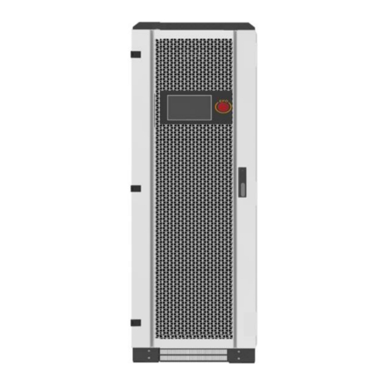
3.2 Product Appearance The appearance and external components of the energy storage inverter are described as follows: 30 kW 100 kW 50 kW 150 kW EPO emergency stop button ※: 250kW and 500kW are split models, 250kW consists of a photovoltaic controller and an energy storage inverter, and 500kW consists of two photovoltaic controllers and an energy storage inverter. -
Page 12: Product Application
3.3 Product Application The energy storage converters are suitable for mine off-grid, island off-grid, villages and towns without electricity (power shortage), rural off-grid, energy storage converter product application as shown in Figure 3-2 below: Energy storage Inverter User load Battery Generator (Either generator or grid,or connected through ATS) -
Page 13: Communication Solutions
3.5 Communication Solutions 3.5.1 BMS Communication scheme Through CAN/RS485 communication cable, energy storage inverter can communicate with BMS to realize data transmission. CAN/RS485 Figure3-3 BMS transmits data through CAN/RS485 3.5.2 EMS Communication scheme Through Ethernet/RS485 communication line, the energy storage inverter can communicate with EMS, and monitor the energy storage system independently designed. -
Page 14: Technical Parmeter Table
3.6 Technical Parmeter Table Type 30 kW 50 kW 100 kW 150 kW 250 kW 500 kW AC (Grid Connection) Max output power[kVA] 33kVA 55kVA 110kVA 165kVA 275kVA 550kVA Rated Power [kW] 30kW 50kW 100kW 150kW 250kW 500kW Rated Voltage [V]... -
Page 15: Inverter Mode And Function
Inverter Mode and Function 4.1 Working Mode Introduction The energy storage inverter working mode can be set on the touch screen, and the user can select the working mode according to different needs (for reference) by clicking the "Operation Mode" in the "Menu" → "System" → "DC/AC Parameter Setting" item:... -
Page 16: Introduction Of Inverter Status
Notice! If the anti-backflow function is set to be enabled, the system will not supply power to the grid once it enters the three working modes of self-generated and self-used, peak load shifting, and battery priority. 4.2 Introduction of Inverter Status There are six states of energy storage inverter, as shown in Table 4-1 below. - Page 17 Status Description When the energy storage system fails, the inverter will stop working, automatically disconnect the contactor on the AC and DC side, and the main circuit will be disconnected from the battery, power grid or fault load. In the fault state, the system always monitors whether the fault is eliminated or not.
-
Page 18: Mechanical Installation Guidance
Mechanical Installation Guidance 5.1 Precautions Before Installation Installation of this series of energy storage inverters requires simultaneous operation of at least two qualified personnel, and all electrical installations must conform to local electrical installation standards. When installing, do not touch other parts of the cabinet except the terminal. ... -
Page 19: Installation Preparation
5.3 Installation Preparation 5.3.1 Packaging Inspection Before installation, it is necessary to check whether the equipment is damaged. If any transportation damage is found, please contact the transportation company. and provide photos of the damage. 5.3.2Delivery Checklist According to the packing list in the packing box, check whether all the parts delivered are complete or not: transportation Table 5-1 Delivery list project... -
Page 20: Machine Transportation
5.4 Machine Transportation 5.4.1 Transport Instructions In order to keep the inverter in a better protective state, packaged transportation should be adopted as far as possible. When using forklift or crane for transportation, attention should be paid to the weight of inverter to ensure that transport equipment has sufficient carrying capacity, and reasonable arrangement of support or lifting points. - Page 21 5.4.2 Forklift Transportation The following is a sketch of using forklift trucks to transport with or without packaging. When transporting without packing, be sure to unload the fender for transporting. In the course of transportation, the center of gravity of the box device should fall between the two forks of the forklift truck.
-
Page 22: Location And Fixation
The mechanical dimensions of each type of inverters are shown in Table 5-6 below. Users can design and install according to this data. Table 5-6 Dimensions of inverters Type Power Size(W×D×H) 30 kW 800×800×1900(mm) 50 kW 800×800×1900(mm) 100 kW 1200×800×2050(mm) 150 kW 1200×800×2050(mm) - Page 23 5.5.3 Base Mounting The bottom of this series inverters should be connected with the base reliably. The bottom of the inverter has a fixed hole for fixing the inverter on the bottom support channel steel or on the ground. As shown in the following figure: ≥1000mm Cover plate...
-
Page 24: Design And Installation Of Air Ducts
5.6 Design And Installation Of Air Ducts 5.6.1 Forced Air Cooling System The energy storage inverters use forced air cooling for heat dissipation, and need to maintain adequate air intake. Table 5-6 Min. area of customer shutters for air intake ( m2 ) Type Power 30/50 kW 0.543858... - Page 25 Internal Ventilation Hose External duct rain shield Figure 5-7 Schematic diagram of inverter external duct ※: The specific air duct design should be reasonably designed according to different models combined with the site environment. Specific requirements for adding air ducts to inverters are as follows: ...
-
Page 26: Electrical Installation Guidance
Table 6-1 Specifications of power cables for the inverters Type Ground Positive and negative DC Type capacity Zero line capacity wire input (per pole) 30 kW ≥25���� ×3 ≥25���� ≥16���� input 50���� 50���� /group 50 kW ≥35���� ×3 ≥35����... -
Page 27: Connection Terminal
The equipment does not have external cables. The above cable recommendation table is not provided by inverters. Users are requested to provide their own cables according to relevant needs. CAUTION All external cables are connected to the corresponding position after entering the equipment through the bottom entry and exit holes. -
Page 28: Fixation And Protection Of Connecting Cables
6.4 Fixation and Protection of Connecting Cables 6.4.1 Cable Fixation In order to prevent loosening of the copper nose, causing poor contact, or increasing contact resistance leading to fever or even fire, it is necessary to ensure that the screw fastening the terminal meets the torque requirements listed in Table 6-4: Table 6-4 Screw dimensions and required torques Screw size... -
Page 29: Installation Dimension Wiring Diagram
6.5.2 Installation Of Lower Fender The energy storage inverters have lower fencing boards at the bottom of front, back, left and right. They are packaged and placed at the bottom of the packaging box. Before installation, all lower fencing boards of the inverter must be removed and put out. After the inverter is positioned and the screw is locked, the lower fencing boards shall be installed. -
Page 30: Ac Side Wiring
In order to avoid personal and equipment injury, wiring must be carried out without electricity. DC switch is off. Multimeter is used to measure that the DC side wiring row is not live. DANGER DC input voltage limit. Confirm that the DC input voltage should not exceed 850VDC! ... -
Page 31: Communication Cable Wiring
6.9 Communication cable wiring The back of the touch screen has reserved the communication line for the external customer interface. Please connect the communication line to the terminal on the back of the touch screen correctly. The description of the external customer interface communication silk screen is shown in Figure 6-5: ※: The communication line can be fine-tuned according to the technical agreemen Battery-BMS.CANH... -
Page 32: Installation Is Complete
When connecting the ground wire of the 500kW split model, please connect the ground terminal of PMDE1 to the ground terminal of PCS, and then connect the ground terminal of PMDE2 to the ground terminal of PCS respectively. ※: The ground wire of the split model is connected to the PCS, please do not connect the ground terminal of PMDE1 to the ground terminal of PMDE2. -
Page 33: Test Run
Test Run 7.1 Pre-Boot Check Before commissioning, a thorough inspection of the installation of the equipment should be carried out, especially to check whether the DC and AC voltages meet the requirements of the inverter, as well as whether the polarity and phase sequence are correct. Check that all connections have met the requirements of the relevant standards and specifications. -
Page 34: Start-Up Operation Flow
Step 4: Check other content After completing the above check before starting, the following items need to be carefully checked to ensure that they are correct. All links are made in accordance with Chapter 6 of this manual. The protective shield inside the equipment has been firmly installed. ... - Page 35 (1) Confirm the photovoltaic input, and close the photovoltaic input switches QPV1 and QPV2 in Figure 7-1. After closing the PV input switch, if the monitor screen was black before, the monitor screen will start running at this time. (When photovoltaic power is transmitted, each photovoltaic channel must be measured to prevent short circuit).
- Page 36 Take 500KW as an example, check whether there is a red alarm signal in the upper right corner of the monitor, and it can be turned on if there is no red alarm signal. Homepage Real-time date System Record Switch machine Standby Figure 7-3 Main menu (6) The photovoltaic controller is turned on.
-
Page 37: Shutdown Operation Flow
7.3 Shutdown Operation Flow 7.3.1Normal shutdown During normal maintenance or overhaul, shutdown operation should be carried out according to the following procedures: Step 1: Through the switch menu on the touch screen, click "Inverter Close"; Step 2: When the AC contactor is disconnected and the touch screen shows that after the "inverter"... - Page 38 7.3.3 Use of maintenance bypass The maintenance bypass circuit breaker (MAINTENANCE) in Figure 7-1 is normally in the off state. The maintenance bypass is to ensure that the load is not powered off when the energy storage inverter is overhauled or faulty (provided that the grid is powered), and the maintenance bypass is closed.
-
Page 39: Touch Screen Operational Guidelines
Touch Screen Operational Guidelines 8.1 Introduction of Touch Screen 8.1.1 Operation interface Taking 500KW as an example, the LCD touch screen is installed on the front of the converter cabinet door. Users can monitor the converter through the LCD screen, read the data of the converter, and set the parameters of the converter. -
Page 40: Alarm Buzzer
8.1.2 User Password The energy storage converter is restarted or the touch screen has not been touched for a long time (10 minutes), and then click the general setting or "system" setting button again, a password input interface will pop up, and the password is: 123. Table 8-2 Indicator status Indicator light Function... -
Page 41: Main Interfaces Introduction
8.4 Main interfaces introduction 8.4.1 Homepage introduction Taking 500KW as an example, the main interface mainly displays machine model, time, battery information, inverter information, running status, and alarm information. As shown in Figure 8-2 below: Alarm status Set the time Load Inverter Host inverter status... - Page 42 Table 8-4 Menu expansion items Serial Menu Menu item Parameter function number name When connected to a lithium battery, the battery analog quantity, status quantity and alarm quantity will be displayed; if a lead-acid Battery battery is connected, the lead-acid battery data interface will be displayed.
- Page 43 "Menu" → "Status" to enter the status main interface. In this interface, the user can query the four data of "data", "status", "alarm" and "battery data", and the user can monitor the converter by observing the feedback data of these four real-time quantities, as shown in Figure 8 -4 shows: Figure 8-4 Inverter Data Interface There are 12 buttons under the data list representing the number of DCDC modules.
- Page 44 8.4.3 Introduction to Record Menu Figure 8-6 Recording menu interface The user clicks "Menu" → "Record" to enter the record menu interface, where the user can click to query "Data Report", "Export Data", "Historical Record" and "Operation Log". The function of this part is to collect the charge and discharge capacity and operation records of the energy storage inverter for easy query.
- Page 45 8.4.4 Introduction to System Settings Menu In the menu interface, you can click "Settings" → "System", "DC/AC Parameter Setting", "DC/DC Parameter Setting", "Battery Setting", "Automatic Running Time Setting", "System Information". Figure 8-8 DC/AC parameter setting The energy storage inverter grid-connected mode: Users can set grid-connected, off-grid or automatic here.
- Page 46 CC is constant current mode, MPPT photovoltaic automatic tracking mode, the default is MPPT mode. Boost/buck: When the input voltage is greater than the output voltage, it is set to buck mode; when the input voltage is less than the output voltage, it is set to boost mode (factory settings are applied according to the project).
- Page 47 8.4.6 Automatic running time setting In the system menu, click "automatic running time" to enter the setting of peak-shaving and valley-filling charging and discharging time. Users can set it according to the local electricity price difference or the real peak-valley electricity consumption time. Figure 8-11 Automatic running time setting 8.4.7 System Information The system information interface displays the protocol version and IP address settings of the...
-
Page 48: Advanced Settings
8.5 Advanced Settings How to enter the advanced settings: "Menu" → "System" → "DCAC Parameters" → "Advanced Settings". Advanced settings are divided into four parts: function settings, system parameters, DCAC debugging, and DCDC debugging. Figure 8-13 Function Settings Battery type: Choose the battery type according to the actual situation, there are two types of lithium battery and lead-acid to choose from. -
Page 49: Energy Storage Inverter Program Upgrade
8.6 Energy storage inverter program upgrade U disk using FAT32 file system (usually U disk is in this format) (capacity ≤ 32G). Put the upgrade file in the root directory of the U disk (the outermost part of the U disk and cannot be placed in the folder of the U disk). -
Page 50: Maintenance And Troubleshooting
Maintenance and troubleshooting 9.1 Explain Due to the influence of ambient temperature, humidity, dust and vibration, the internal devices of energy storage inverter will be aging, which will affect the performance of inverter and can even lead to failure. Therefore, it is necessary to carry out routine and regular maintenance of energy storage inverter to ensure its normal operation and service life. - Page 51 If only the circuit breaker is disconnected, the cable connection terminals in the AC/DC cabinet of the energy storage inverter are still live! Before opening the cabinet door and starting the formal maintenance work, it is necessary to disconnect not only the circuit breaker, but also the front and back stage circuit breakers WARNING of the energy storage inverter.
-
Page 52: Fault Handling
The overwhelming majority of maintenance work can only be carried out by removing the protective net cover inside the machine. At the end of all maintenance work, it is necessary to restore all dismantled maintenance covers to their original state. Make sure all screws are tightened in place WARNING Only the recommended product routine maintenance cycle is included in the table. - Page 53 9.3.2 Non-Alarm Inducing Failure Machine working noise is high Check whether the power is in the normal range; Measure whether the grid-connected current and voltage waveforms are normal; Check the replacement of cooling fans. Network communication mode: Please check whether the IP address, subnet mask and gateway are set correctly. ...
- Page 54 Fault Type Processing Method Outputcontactor open circuit Turn off and check if AC contactor is damaged Output Contactor Short Circuit Turn off and check if AC contactor is damaged AC Fan Fault Turn off and check AC fans AC auxiliary power failure Turn off and check the AC auxiliary power supply board DC auxiliary power supply failure Turn off and check DC auxiliary power supply board...
- Page 55 Table 9-3 DCDC Alarm Fault Handling Method Fault Type Processing Method DC converter overcurrent Shut down, troubleshoot, and turn on after the trouble is eliminated Wave-by-wave current limiting Shut down, troubleshoot, and turn on after the trouble is eliminated of DC converters DC converter over temperature Shut down, troubleshoot, and turn on after the trouble is eliminated Output overload...
- Page 56 Fault Type Processing Method Abnormal insulation resistance Shut down, disconnect the input and output switches DC auxiliary power failure Shut down, replace the auxiliary power board DC fan failure Shut down, check the fan air duct, power supply Emergency shutdown Shut down, disconnect the input and output switches, check the fault Shut down, disconnect the input and output switches, check the DC converter out of sync...
- Page 57 Function Function Description Over/Under When the energy storage inverter detects that the frequency fluctuation of the Frequency power grid exceeds the allowable range, the energy storage inverter will stop Protection of Power working and send out warning signals. The fault type is displayed on the LCD screen. Grid Energy storage inverter can detect abnormal frequency quickly and respond to it.
- Page 58 Function Function Description Independent When the energy storage inverter operates in the independent inverting mode and Inverter detects that the three-phase output voltage exceeds the allowable voltage range, Overvoltage the energy storage inverter will stop working and send out warning signals, and Protection display the fault type on the liquid crystal.
-
Page 59: Appendix I: Quality Assurance
Appendix I: Quality Assurance Products that fail during quality assurance. We will repair or replace new products free of charge. Evidence During the warranty period, the company requires customers to produce invoices and dates for purchasing products. At the same time, the trademark on the product should be clearly visible, otherwise it has the right not to give quality assurance.
Need help?
Do you have a question about the 30 kW and is the answer not in the manual?
Questions and answers