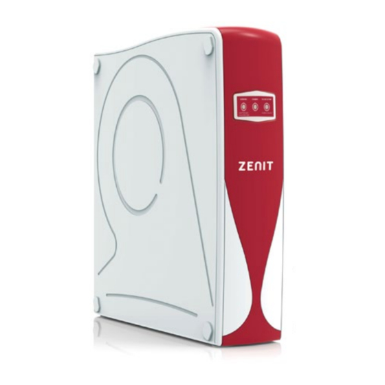
Summary of Contents for Hidro-Water ZENIT
- Page 1 RESIDENTIAL REVERSE OSMOSIS USER / INSTALLER’S MANUAL MA-ES-RO-ZENIT_RO-0236-02_FL_20_V02...
-
Page 2: Table Of Contents
4.3.- Drain clamp installation (Figure-6) ....................7 Please read this manual carefully following the warnings listed below before go-ing ahead with the installation and use of the ZENIT osmosis system. If you have any doubts, 4.4.- Membranes installation (Figure-2) ....................7 please contact your official distributor. - Page 3 The installation should be done by professionally qualified personnel and should not be installed close to a heat source. • The ZENIT osmosis system needs a mains current of 220 – 240V less than 1 metre away. • Do not repair or take the system apart on your own. If the system is not working correctly, contact your official distributor.
-
Page 4: Installation
Take off the right-hand-side cover of the ZENIT osmosis system (looking the system from the front). To do so, you must unscrew the screws at the corners of that side cover, having previously removed the protective caps that hide them, as shown in the picture below. -
Page 5: Osmosis System Installation
c. Open the membrane housing caps, turning them anti-clockwise with the help of 4.5.- Osmosis system installation the wrench supplied with the system (Figure-16). The hydraulic connections should follow the contour of the surface chosen for installation so that the tubes do not get mixed up or tangled. Leave a sufficient length of tube to ease moving the system during future maintenance. -
Page 6: Osmosis System Start-Up
The other end of the ⅜” tube must be connected to the inlet of the ZENIT osmosis 5.- OSMOSIS SYSTEM START-UP system (Figure-1), where it is marked “FEED WATER IN”. Insert it fully. Once inserted put on the ⅜” security clip. -
Page 7: User Interface
CONGRATULATIONS! YOUR SYSTEM IS ALREADY FULLY INSTALLED AND RUNNING osmosis system, the warranty will be void. 6.- USER INTERFACE The ZENIT osmosis system has a user interface system, made up of 3 LEDS, which Cartridge type Carbon GAC cartri- Carbon CTO cartrid-... -
Page 8: Procedure For Replacing Cartridges And The Membranes
To g. To change the postfilter (5th stage), take off the right-hand-side cover of the ZENIT do so, you must remove the corresponding security clips. Then remove the car- osmosis system (looking the system from the front) as indicated in point 4.4 of this... -
Page 9: Troubleshooting
Once you’ve checked that there’s no leaks, replace the right-hand-side cover of SYMPTOM PROBABLE CAUSE SOLUTION the ZENIT osmosis system (looking the system from the front) as indicated in paragraph 5.k of this manual. No water supply. Wait until the water supply has been restored. -
Page 10: Monitoring And Maintenance Control
8.- MONITORING AND MAINTENANCE CONTROL SYMPTÔME CAUSE PROBABLE SOLUTION Worn post filter. Replace post filter. Plastic or DATE: synthetic taste SERVICE MADE NEXT SERVICE OBSERVATIONS Contamination. Change the filters, membranes, post filter and Sediments, GAC y CTO cart. change sanitise. Unpleasant taste and smell Membrane change... - Page 11 DATE: DATE: SERVICE MADE NEXT SERVICE OBSERVATIONS SERVICE MADE NEXT SERVICE OBSERVATIONS Sediments, GAC y CTO cart. change Sediments, GAC y CTO cart. change Membrane change Membrane change Postfilter change Postfilter change Sanitization Sanitization Reparation Reparation Name and signature of the authorised technician or distributor: Name and signature of the authorised technician or distributor: DATE: DATE:...
-
Page 12: Osmosis System Spare Parts
10.- OSMOSIS SYSTEM SPARE PARTS CODE DESCRIPTION OI-0209-12 ZENIT top red cover OI-0209-14 ZENIT frontal red cover OI-0209-10 ZENIT structure case OI-0209-18 ZENIT protective caps OI-0207-64 New Look faucet OI-0209-20 ZENIT case wrench OI-0234-10 5 in 1 Wrench OI-0235-30 ZENIT electronic circuit board TG-A6ME4 Male elbow ¼”... - Page 13 NOTES CODE DESCRIPTION OI-0207-117 1/8” M x ¼” T Non-return elbow piece OI-0207-02 Male Elbow ¼” M x ¼” T OI-0230-12 1500 cc Flow restrictor OI-0207-18 Tee ¼” M x ¼” T x ¼” T OI-0234-68 220 V – 48 V Power supply ME-2003-03 20x12 200GPD Membrane TG-A6BU6...
- Page 14 NOTES NOTES MA-ES-RO-ZENIT_RO-0236-02_FL_20_V02 MA-ES-RO-ZENIT_RO-0236-02_FL_20_V02...
- Page 15 Hidro Water, S.L.U. Carretera Chirivella-Aldaya, 48 46960 Aldaya · Valencia, Spain Tel: (+34) 961 98 62 30 hidrowater@hidro-water.com www.hidro-water.com DISTRIBUTOR INSTALLER Sale date Instalation date Stamp: Stamp: MA-ES-RO-ZENIT_RO-0236-02_FL_20_V02...


Need help?
Do you have a question about the ZENIT and is the answer not in the manual?
Questions and answers