
Related Manuals for PSI FMT150


Summary of Contents for PSI FMT150
- Page 1 Photobioreactor FMT150 Manual and User Guide Please read this manual before operating the product. Copyright 2015 PSI, spol. s r. o., Drásov 470, 664 24 Drásov, Czech Republic www.psi.cz...
-
Page 2: Table Of Contents
2. General Description................................5 3. Device Description................................6 3.1 Configurations and Versions.............................8 3.2 Standard Components............................11 3.3 Control Unit Front Panel............................14 3.4 Rear Panel for version FMT150.1..........................16 3.5 Rear Panel for version FMT150.2..........................18 3.6 Connection Schema..............................19 4. Device Installation................................21 4.1 Power Supply................................21 4.2 Cultivation Vessel..............................22 4.3 pH/Temperature Sensor............................26... - Page 3 8.2 QY measurement..............................70 8.3 Technical Specification Standards...........................71 9. Warranty Terms and Conditions.............................75 10. List of Abbreviations..............................78 Page 3...
-
Page 4: Warnings And Safety Precautions
1.Warnings and Safety Precautions WARNINGS AND SAFETY PRECAUTIONS PLEASE READ THE FOLLOWING INSTRUCTIONS CAREFULLY BEFORE TURNING THE PHOTOBIOREACTOR ON: Remove all packaging and transport protectors before connecting the photobioreactor to the power supply. • Use only cables supplied by the manufacturer. •... -
Page 5: General Description
Turbidostatic cultivation can be used for the stabilization of the suspensions via optical density control. In addition, up to 8 peristaltic pumps for different chemostat cultivation control can be linked to the Photobioreactor FMT150 for the highly precise control of cultivation conditions. -
Page 6: Device Description
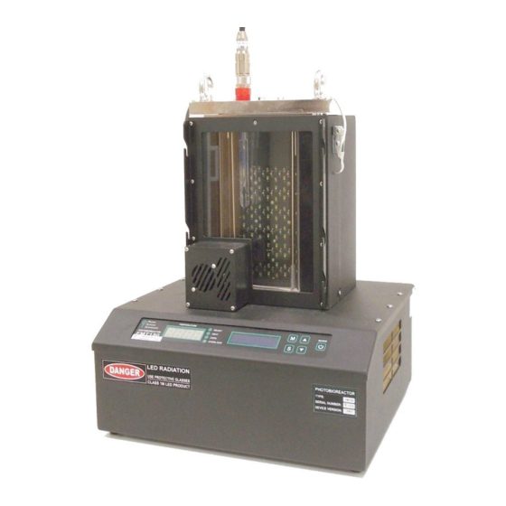
3.Device Description DEVICE DESCRIPTION Standard version of the Photobioreactor FMT150 consists of a cultivation vessel with a sealable lid and a base box containing electronics circuitry, LED light panel (Fig. 1A) and other components essential for the optimal operation of the photobioreactor. - Page 7 3.Device Description The array of high-power light emitting diodes (LEDs) is located behind the cultivation vessel. In the bottom corner of the front of the vessel is a semiconductor light sensor for measuring fluorescence emission and suspension optical density by attenuation of light that was emitted from the LEDs (Fig. 1E) The Photobioreactor can also control external modules such as peristaltic pumps and solenoid valves via the photobioreactor control unit (shown schematically in Fig.
-
Page 8: Configurations And Versions
Numerous additional accessories such as various sensors can be supplied as described in chapter 5 on page 30. Please note that this manual describes operation of two FMT150 versions (Fig. 4) - older PBR FMT150.1 and new PBR FMT150.2. - Page 9 Optional enhanced range 0 – 70 °C (static or ramping) (requires enhanced vessel made from nickel-plated • brass covered with ceramic layer). 3.1.4 VERSIONS The available vessel capacity for two FMT150 versions: FMT150.1 – 400 ml, 1000 ml • FMT150.2 – 400 ml, 1000 ml, 3000 ml •...
- Page 10 3.Device Description Important: The FMT150 in both 400 and 1000 ml models has been upgraded from FMT150.1 (Fig. 4A) to FMT150.2 (Fig. 4B). This manual provides instructions for operation of both versions (original, now referred to FMT150.1 and the current version FMT150.2). Please always ensure that you refer to correct instructions.
-
Page 11: Standard Components
Table 2: FMT150 measured parameters STANDARD COMPONENTS Photobioreactor FMT150 can be purchased in different configurations from minimal up to complex system consisting of numerous accessories linked together. They can be controlled via the Photobioreactor control unit itself or by the... - Page 12 Power supply with the power cord. Photobioreactor with integrated double-modulation fluorometer- Ft, Fm, QY and integrated optical density measurement. 3. Cultivation vessel with capacity 400 ml (with holder) for FMT150/400, 1000 ml for FMT150/1000 or 3000 ml for FMT150/3000. LED panel shield.
- Page 13 3.Device Description Fig. 5: Components of the spare part kit. Numbers correspond to component numbers in Table 3. Component Component Description Specification Explanation Number Male Luer Integral Lock MTLL240-J1A* 5/32” (4.0 mm) Female Luer Thread Style BSFTLL-J1A* 5/16” Hex to 1/4-28 UNF Bottom Sealing Thread Female Luer Thread Style FTLL240-1* 5/32”...
-
Page 14: Control Unit Front Panel
Please note that neither turbidostat nor chemostat module can be operated if FMT150 is purchased without the PBR software. The front panel of the FMT150 control unit has 4 LED lights on the left and 5 control keys on the right (Fig. 7). Page 14... - Page 15 • occurs. 3.3.3 DISPLAY ON THE RIGHT This display shows various functions of the FMT150 and these are activated and set with the main keys on the right side of the control unit as described below. 3.3.4 MAIN KEYS [M]: Used to move back in the menu tree or to exit the menu.
-
Page 16: Rear Panel For Version Fmt150.1
3.4.2 CONNECTOR FOR OPTIONAL SENSOR sensor should be plugged to this connector when in use. PBR FMT150 control unit recognizes when the sensor is connected and will automatically control the operation of the sensor. Note: Only O sensor can be plugged to this connector. - Page 17 3.4.8 IDENTIFICATION LABEL WITH SERIAL NUMBER Each Photobioreactor FMT150 produced has a serial number that corresponds with the serial number of the power supply unit. These are always provided together and are not interchangeable. Prior to switching PBR FMT150 device ON make sure that the serial number on the rear panel of the main body matches the serial number on the power supply (Fig.
-
Page 18: Rear Panel For Version Fmt150.2
USB communication cable is provided as part of the PBR FMT150 package when purchased with the Remote Control System to connect the PBR FMT150 with the computer. This connection has to be made for the communication of the PBR FMT150 via the PBR software. -
Page 19: Connection Schema
Depending on the use of optional modules and the set-up of the PBR FMT150, the connection schema for the optional and standard modules with the PBR FMT150 control unit rear panel may differ. Please refer to Table 4 below to see the possible order of connecting the different modules to the PBR FMT rear panel. - Page 20 Please note that the AUX3 and AUX4 connectors are available only in the FMT150.2. Fig. 10: Schematic of recommended set-up for interconnecting available modules with PBR FMT150 control unit. A) Scheme valid for FMT150.1 version. B) Scheme valid for FMT150.2 version.
-
Page 21: Device Installation
4.Device Installation DEVICE INSTALLATION To install the device properly, it is necessary to follow the proper sequence of the assembly instructions. Instructions for assembly of standard PBR FMT150 (400, 1000 and 3000 ml) are described below. POWER SUPPLY Make sure that both the Photobioreactor and the power supply are switched OFF. -
Page 22: Cultivation Vessel
It is strongly recommended to use back-up UPS system to protect the PBR FMT150 system from power outage. If UPS system is not used and the AC power is turned off unexpectedly the PBR FMT150.1 control unit needs to be switched ON with the MAINS key. After switching the unit ON, all previous settings will be reset. Please note that if PBR software is used and the power outage occurred all previous settings will be restored and the currently running experiments will continue. - Page 23 (n°6 in Fig. 13A,C). Note: Sampling tube can be used as gas outlet when Gas Analysis System (GAS) is connected to the PBR FMT150; for more information see page 48.
- Page 24 Connect the gas dispenser tubing to the two luer connectors as shown in Fig. 14A,B. Note: Standard version of the PBR FMT150 is connected according to the Fig. 13B, when optional modules such as peristaltic pump or GAS and GMS are used see page 45 and 48 for further instructions).
- Page 25 4.2.4 3000 ML VESSEL SPECIFICS The PBR FMT150/3000 provides more connectors than in 400/1000 ml models to give the user broader range of connected optional instruments and larger scope of operational features. Please refer to Fig. 15 for detail description of the 3000ml vessel lid and all the connectors: (2) Holders for easy vessel manipulation.
-
Page 26: Ph/Temperature Sensor
(described in chapter 3.2) and is recommended for purchase if precise control of cultivation conditions is required. The module consists of electronic unit embedded in Photobioreactor FMT150 Control Unit, probe and communication cable (Fig. 21). - Page 27 Prior to initiation of each experiment it is recommended to perform the pH sensor calibration. The calibration can be done either in PBR software (for more details see PBR Software manual) or using the FMT150 control unit front panel as described below.
-
Page 28: Gas Supply
4.Device Installation Fig. 17: pH sensor calibration. A) Electrode is placed into the solution of pH 7. B) Reading of the measured value. C, D, E) Grounding with the copper cable for the calibration of InPro3253/120/PT1000 version of the electrode. GAS SUPPLY The gas supply to the photobioreactor consists of four main parts –... - Page 29 Fig. 19. Connect 20 µm air filter (Note: air filter is not part of the components provided with PBR FMT150) with the MTLL Luer Lock end of the silicon tubing from the humidifier bottle and via other FTLL Luer Lock connect with the silicon tubing coming from the bubble interruption valve.
-
Page 30: Optional Accessories/Components
OPTIONAL ACCESSORIES/COMPONENTS The functions of the PBR FMT150 may be enhanced by wide range of optional components. Installation and operation of the optional accessories that can be provided together with the PBR FMT150 device are described in next chapters. PBR SOFTWARE The Photobioreactor can be connected with an external PC that runs PBR software (Fig. -
Page 31: Ph/Temperature Module
O concentration in the culture medium. The module consists of electronic unit embedded in Photobioreactor FMT150 Control Unit, sensor probe and sensor communication cable (Fig. 22). O sensor InPro6800/12/120 from METTLER TOLEDO (www.mt.com) with integrated temperature probe is used for oxygen measurement. -
Page 32: Co Module
D) Attaching the cable to the rear side of the PBR FMT150.2. When connected to the PBR FMT150 control unit, the sensor is automatically recognized. The function of the sensor can be controlled manually by the front panel of the control unit or by PBR software. For manual control please refer to chapter 8.1 on page 62 for more detailed explanation. - Page 33 5.Optional Accessories/Components InPro5000/12/120 sensor from METTLER TOLEDO (www.mt.com) with integrated temperature probe is used for potentiometric CO concentration measurement. The InPro5000 sensor employs a gas permeable silicone membrane which is tightly stretched around a special engineered flat pH membrane. CO partial pressure can be calculated using the pH and the temperature.
- Page 34 5.Optional Accessories/Components Connect the PBR FMT150 and the dissolved CO module using a provided communication cable. Plug the communication cable into the “AUX IN” connector of the electronic box of the dissolved CO module (Fig. 26C). Plug the other end of the communication cable into the “AUX1” connector at the rear of the Photobioreactor (Fig.
- Page 35 5.Optional Accessories/Components Important: Please note that CO electrode is designed for measurements of dissolved CO in the range from 6x10 mol/L to 2x10 mol/L CO which corresponds to the lower limit of detection around 60 µM dCO (2000 ppm in 25 °C). For measurements of dCO close to ambient CO concentration, it is recommended by the manufacturer to dilute...
- Page 36 5.Optional Accessories/Components CALIBRATION PROCEDURE Calibration and sample solutions should always be kept at the same temperature (if other vessel than PBR vessel is used for calibration it should be thermally insulated from possible heating by the magnetic stirrer). If the PBR vessel is used the solution within the vessel should be maintained at the temperature of the experiments.
- Page 37 Switch ON the PBR FMT150 and place the empty vessel in its holding place. Install the lid of the vessel with the sensor and other ports closed off. Ensure the stirring bar is placed inside the vessel and the magnetic stirrer is installed on the outside of the vessel.
- Page 38 5.Optional Accessories/Components Important: Please monitor the pH of the solution over the time course of the calibration to ensure that it remains at 4 or lower. Add more HCl into the solution if pH increases above 4. At pH above 4 dCO will be converted back into bicarbonate and will no longer be measured by the probe (Fig.
- Page 39 5.Optional Accessories/Components Bubbled gas Temp (µM) (mg/L) 400 ppm CO 25 °C 13.6 5000 ppm CO 25 °C 7.48 10000 ppm CO 25 °C 14.96 15000 ppm CO 25 °C 22.44 Table 6: CO2 calibration example CORRECTION TABLE FOR CO CALIBRATION Correction table for the volume of calibration solution to be added into the vessel for the calibration step in respect of maximum vessel volume.
-
Page 40: Magnetic Stirrer
(Fig. 31 A, B). Important note: PLEASE, DO NOT TURN THE METAL SERVICE BUTTON ON THE REAR SIDE OF POWER SUPPLY UNIT WITHOUT PSI MANUFACTURER ADVICE AND LET IT IN HORIZONTAL POSITION (Fig. 33 D)! Page 40... - Page 41 B) Additional components for V-200 comprise: power adapter, communication cable (AUX), magnetic bars, service keys. C) The obsolete version of magnetic stirrer intended for FMT150.2 was produced as slow 245 and fast rotating 770 model. Production was stopped in 2015.
- Page 42 5.Optional Accessories/Components Fig. 32: Relation between rotation speed of magnetic stirrer (in rpm) and PWM regulation applied in %. A) V-200 version B) Obsolete slow-speed (245) and high-speed (770) magnetic stirrer version for PBR FMT150.1 or 150.2. 5.6.1 INSTALLATION Mount the magnetic stirrer: place the inner side of the stirrer towards the PBR front window as shown in Fig.
- Page 43 D) The rear side of the stirrer power supply contains SERVICE key (must be in horizontal position) E) The rear side of PBR main unit with all connectors typical for FMT150.2 – arrow emphasizes plug for AUX communication cable F) The back side of PBR unit with connectors typical for FMT150.1 – AUX1 connector for communication with magnetic stirrer.
- Page 44 PWM Pump when connected to the PBR has to be set for REMOTE MODE operation to be directly controlled and operated via Remote Control software for PBR FMT150. This pump can also be used in a manual mode as a stand-alone instrument.
-
Page 45: Gas Mixing System Gms 150
5.Optional Accessories/Components For the stand-alone MANUAL mode operation connect the PWM Pump power supply with the PWM Pump and plug to AC outlet. The flow rate can be controlled manually with the speed control knob on the front panel. Important: If MANUAL mode of the PWM Pump is used for controlling air bubbling in the cultivation vessel, bubble interruption valve must be used to interrupt the bubbling during the measurements. - Page 46 Note: It is recommended to place the GM System no a shelf above the PBR to prevent a flooding of the system. When the GM System is connected to the PBR FMT150 the vessel lid assembly scheme (Fig. 37B) is same as •...
- Page 47 5.Optional Accessories/Components Fig. 37: GM system connection with the PBR FMT150. A) Mixed gas of given composition (1) is pumped from GM System via (2) to the PBR FMT150 via air interruption valve (3). B) Vessel lid assembly. (4) Air distribution tube, (7) Medium outlet, (6) Sampling tube.
-
Page 48: Gas Analysis System Gas 150
5.Optional Accessories/Components A connection of more PBR FMT150 units with one GMS 150 is shown in Fig. 38. Please note, this configuration is not that precise as the connection of one PBR with one GMS 150 unit which is recommended. However, following set-up may be used for particular cases. - Page 49 Fig. 39: GAS 150. 5.8.1 INSTALLATION Follow the instructions below to connect the Gas Analysis System 150 (GAS 150) with the PBR FMT150: Connect the GAS 150 with the AC power cord which is part of the accessory GAS 150 package (Error: Reference source not foundA) and plug to electrical outlet.
- Page 50 GMS 150 and peristaltic pumps. Numbers correspond to: 1-GMS 150 output; 2-GAS 150 input for mixed air from GMS 150; 3-GAS output for bringing the mixed air to humidifier bottle (4) and to the PBR FMT150. 5-Input for gas from the cultivation vessel to GAS 150.
- Page 51 Fig. 42: Vessel lid assembly when GAS 150 system module is connected to PBR FMT150. A) Lid assembly when peristaltic pumps are connected to PBR FMT150 in parallel with GAS 150 and standard aeration U-tube is used. B) Top view of vessel lid when peristaltic pumps are connected to PBR FMT150 in parallel with GAS 150. Letters in yellow circles refer to: A-Aeration tubing;...
-
Page 52: Peristaltic Pump Pp500
PBR software is required to use the pump in turbidostat or chemostat mode. Note: the operation of the peristaltic pump cannot be controlled by the front panel of the PBR FMT150 control unit. Without the PBR software, the operation of peristaltic pump is controlled solely by the Peristaltic pump Control display. - Page 53 INSTALLATION Follow the instructions below to install and operate the peristaltic pump: First install the tubing connection with the PBR FMT150. • Attach provided short tube with Male Luer Lock Fittings (n°1 in Table 3) to the Peristaltic Pump PP500. Insert •...
- Page 54 5.Optional Accessories/Components Fig. 45: Assembly of the peristaltic pump. A, B) Short tube is attached around the rotor wheel to the peristaltic pump. C, D) Adapter is attached to the silicone tubing and connected with the tubing of the peristaltic pump. E) Tubing from the peristaltic pump is connected with the cultivation vessel.
- Page 55 Fig. 46: Final assembly of the peristaltic pump. A) Second luer connector is attached. B) Connection of the silicone tubing with the culture for the cultivation. C) Fully installed peristaltic pump tubing. D) Schematic representation of PBR FMT150 unit connected to peristaltic pumps in chemostat and turbidostat mode and to GMS 150.
-
Page 56: External Light Panel
5.Optional Accessories/Components Fig. 47: Connection of peristaltic pump with PBR FMT150.2. 5.10 EXTERNAL LIGHT PANEL The Photobioreactor can be supplemented with an additional external light panel that helps to accommodate specific needs of different organisms or to increase illumination intensity. External light panel is offered in three versions: single color •... -
Page 57: Additional Software License
5.Optional Accessories/Components Fig. 48: Correct positioning of the external light panel and the final set up of the PBR with the external light source. The function of the external light is controlled manually by the front panel of the PBR control unit or by PBR software. For manual operation via front panel please refer to chapter 8.1 on page 62. - Page 58 5.Optional Accessories/Components 5.13.6 SUPPLEMENTARY VESSEL (STANDARD MODEL) Additional vessel, suitable for cultivation in the range of 18 – 50 °C. Made from stainless steel and glass, it includes the frame, lid and glass body. Manufactured in a 400 ml, 1000 ml or 3000 ml version. 5.13.7 ENHANCED VESSEL Suitable for cultivation in the range of 0 –...
-
Page 59: Cultivation Guide
6.Cultivation Guide CULTIVATION GUIDE This section describes show to set up a standard Photobioreactor FMT150 and how to initiate cultivation of an algal culture with a PBR software. SET UP THE COMPONENTS 1. First prepare the glass cultivation vessel and its lid. Follow the steps described in chapter 4.2.3 on page 24 to assemble the vessel. - Page 60 When using the photobioreactor without the PBR software, follow the manual instructions for the setup of the growth parameters using the front panel of the PBR FMT150 control unit and as described in chapter 8.1 on page 62. Page 60...
-
Page 61: Troubleshooting And Customer Support
7.Troubleshooting and Customer Support TROUBLESHOOTING AND CUSTOMER SUPPORT In case of troubles and for customer support, please, write to support@psi.cz with subject Bioreactor or contact your local distributor. Page 61... -
Page 62: Appendix
APPENDIX FMT150 CONTROL MENU TREE This section explains the operation of the Photobioreactor FMT150 control. Photobioreactor can operate in cultivation mode by setting the cultivations parameters such as light, temperature, etc. in the menu navigation tree. Please note that even though various parameters such as chlorophyll fluorescence and OD, temperature, etc can be measured, the values and data are not recorded and are only displayed at the time of the measurement. - Page 63 8.Appendix * The display of the Photobioreactor does not reflect this color differentiation. 8.1.2 OPERATION SCHEMATIC Page 63...
- Page 64 8.Appendix Page 64...
- Page 65 8.Appendix Page 65...
- Page 66 8.Appendix Page 66...
- Page 67 8.Appendix Page 67...
- Page 68 8.Appendix Page 68...
- Page 69 Control keys used are described in detail in Appendix on page 62. Note: Please note that the Pulse Light Control protocol can be operated only via front panel of the PBR FMT150 control unit and is currently not supported in PBR software.
-
Page 70: Qy Measurement
8.Appendix QY MEASUREMENT Below is shown schematic description of the QY measurement. Fig. 50: QY measurement theory Page 70... -
Page 71: Technical Specification Standards
/s. Other LED colors available as an option. OD - Optical Density Measurement: Real time measurement of OD by two LEDs (735 nm for version FMT150.1, 720 nm for version FMT150.2, 680 nm for both FMT 150.1 and FMT150.2) Detector Wavelength Range:... - Page 72 /s. Other LED colors available as an option. OD - Optical Density Measurement: Real time measurement of OD by two LEDs (735 nm for version FMT150.1, 720 nm for version FMT150.2, 680 nm for both FMT 150.1 and FMT150.2) Detector Wavelength Range:...
- Page 73 Up to 8 peristaltic pumps (optional) Probes (pH, O , CO Optional BIOS: Upgradeable firmware Communication Port: USB port for FMT150.2 Cultivation Vessel Material: Glass, stainless steel, duralumin, silicone sealing Size: 50 x 35 x 31 cm Weight: 28 kg...
- Page 74 8.Appendix 8.3.4 GAS 150 Warm-up time: 45 minutes Input/Output Connector: Parker Prestolock 6 mm Weight: 5 kg Dimensions: 41x37x17 cm Carbon Dioxide Module – Specification: Available CO ranges: 0-2 %, 0-3 %, 0-5 %, 0-10 %, and 0-20 % (please note that if any other than standard range is required, the customer needs to specify the required range) Standard Range: 0-2 % Accuracy at +25 °C (+77 °F) against certified factory references: <±[0.02% CO...
-
Page 75: Warranty Terms And Conditions
9.Warranty Terms and Conditions WARRANTY TERMS AND CONDITIONS This Limited Warranty applies only to the Photobioreactor FMT150. It is valid for one year from the date of shipment. If at any time within this warranty period the instrument does not function as warranted, return it and the manufacturer will repair or replace it at no charge. - Page 76 9.Warranty Terms and Conditions Alphabetical Index Accessory..................................12, 49 Actinic light................................6, 57, 69 AUX..............................16pp., 29, 34, 41pp., 55 Bubble interruption valve....................2, 12, 17, 19, 28pp., 44pp., 48, 51 Calibrations........................22pp., 27p., 31p., 34pp., 45, 59p. Chemostat............................5, 7, 14, 25, 50, 52p., 55 Client....................................59 CO2..................2, 6, 8, 11, 14, 16pp., 23p., 30, 32pp., 45p., 48, 50, 57, 59, 71pp.
- Page 77 9.Warranty Terms and Conditions Pump................2, 5, 7, 12, 16pp., 23pp., 28pp., 34, 42, 44p., 47p., 50pp., 59p., 71pp. PWM...............................14, 17pp., 41pp., 48 QY................................3, 11p., 30, 70, 78 Rear panel..............................2, 16pp., 21, 45 Sensor/probe..................2, 5pp., 13pp., 23pp., 30pp., 40, 42, 57, 59p., 71pp. Spare part kit...................................12p.
-
Page 78: List Of Abbreviations
10.List of Abbreviations 10. LIST OF ABBREVIATIONS E – Actinic Illumination Irradiance , F’ – continuous fluorescence level - continuous fluorescence level of dark adapted sample – maximal fluorescence level F’ – maximal fluorescence level in light-adapted sample variable fluorescence parameter F –...
Need help?
Do you have a question about the FMT150 and is the answer not in the manual?
Questions and answers