
Related Manuals for Fcar FD505


Summary of Contents for Fcar FD505
- Page 1 FCAR FD505 Wheel Alignment System User Manual FD505 Wheel Alignment System User Manual Service and support FCAR TECH USA Phone: 443-380-0088 Address: 7090 Golden Ring Rd, Suite 107, Rosedale, MD 21237 Web: www.fcarusa.com...
-
Page 2: Table Of Contents
FCAR FD505 Wheel Alignment System User Manual Contents STATEMENT ..........ERROR! BOOKMARK NOT DEFINED. CONTENTS ......................2 5D FOUR-WHEEL ALIGNMENT SYSTEM USE PRECAUTIONS ....... 4 FCAR 5D FOUR-WHEEL ALIGNMENT SYSTEM ............ 5 PRODUCT DESCRIPTION ................5 ........5 HEN DO YOU NEED TO DO WHEEL ALIGNMENT ............ - Page 3 FCAR FD505 Wheel Alignment System User Manual 4.2.2 Vehicle pushing compensation ............29 4.2.3 Caster measurement ..............33 ....................37 IFT MODE ................43 EHICLE ADJUSTMENT ..................44 ATA SAVING MAINTENANCE INFORMATION ..............45 SYSTEM SETTING ..................46 ............47...
-
Page 4: Four-Wheel Alignment System Use Precautions
The operator must have a certain basic knowledge of computer application and understand the basic knowledge of four-wheel alignment. ⚫ FCAR 5D four-wheel aligner is a precision instrument and requires a dedicated person to manage the use to avoid collision and fall. ⚫... -
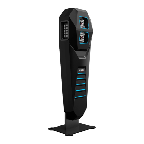
Page 5: Fcar 5D Four-Wheel Alignment System
FCAR 5D four-wheel alignment system Product description FCAR 5D four-wheel alignment system is the product and platform of FCAR self-developed vehicle four-wheel alignment., combined with the application feedback of 3D aligner users and the lack of 3D products. (Field, precision, transportation, installation, shunting, etc.) Through more than 5 years of research and development and test... -
Page 6: Definition Of Wheel Alignment
1.3 Product configuration The general configuration of the FCAR 5D four-wheel alignment system is shown in the following figure. - Page 7 FCAR FD505 Wheel Alignment System User Manual Technical parameter: Measure item Measure accuracy Measure range Camber angle ±0.01° ±8° Caster angle ±0.03° ±19° Front wheel inclination angle ±0.02° ±19° ±0.01° ±2° Rear wheel thrust angle ±0.02° ±2° Rear wheel axle deflection ±0.02°...
- Page 8 FCAR FD505 Wheel Alignment System User Manual Tablet structure diagram Serial Name Description number ① Power Indicator Charging indicator ② Microphone port Voice input ③ Light sensor External light intensity sensing...
-
Page 9: Product Functions And Features
FCAR FD505 Wheel Alignment System User Manual Serial Name Description number TF card slot / 3.5 ④ Storage TF card location / headphone hole headphone hole ⑤ Heat dissipation hole For tablet cooling, avoid overheating ⑥ External horn hole For external sound playback ⑦... -
Page 10: Selection And Use Of Supporting Tools
Selection and use of supporting tools FCAR 5D four-wheel alignment system tools include high-precision fixtures, targets, corner discs, etc. It will be introduced separately in the following. -
Page 11: The Use Of Corner Plate
FCAR FD505 Wheel Alignment System User Manual 2.1 The use of corner plate The 5D four-wheel alignment system is equipped with two corner plates which installed at the front wheel position of the car. Before driving, lock the corner plate with the locking pin to prevent it from rotating. -
Page 12: Four-Wheel Alignment System Installation Method
FCAR FD505 Wheel Alignment System User Manual 2.3 5D Four-wheel alignment system installation method FCAR 5D four-wheel alignment system breaks through the limits of the field and is suitable for a variety of lifting platforms (two columns, four columns, small scissor and large scissors). -
Page 13: Target Selection
FCAR FD505 Wheel Alignment System User Manual 2.3.1 Target selection Please refer to the table below to select the target type according to different lifting platforms:... -
Page 14: Preparations Before Wheel Alignment Operation
FCAR FD505 Wheel Alignment System User Manual Type Physical view Adaptation plan large scissor/small scissor Long target installation plan Two columns installation plan, Trapezoidal target four columns installation plan Tip: the target type selection is complete and must be set in [System Settings], as shown in Chapter 6. -
Page 15: Fixture/Target Installation
Figure 3.1-1 Steering wheel holder installation 3.2 Fixture/target installation FCAR 5D four-wheel alignment system is equipped with 4 fixtures, 4 targets and 2 hosts. The host must be installed in the front position of the head of vehicle in the left and right direction (refer to the 5D four-wheel alignment installation method). - Page 16 FCAR FD505 Wheel Alignment System User Manual Rotate the hand wheel again to adjust and lock the clamp to the rim position. Figure 3.2-1 Fixture installation The physical photo is shown below: Note: When assembling the fixture, the claws should keep away from the lead block on the rim, please make sure that the four claws are in full contact with the rim.
-
Page 17: Device Connection
FCAR FD505 Wheel Alignment System User Manual 3.3 Device connection The interfaces on the back of the main unit are as shown below:... -
Page 18: Host On/Off And Function Menu Main Interface
FCAR FD505 Wheel Alignment System User Manual Serial No. Name Serial No. Name ① ② Power interface HDMI HD output ③ ④ VGA interface USB interface ⑤ ⑥ Handgrip Power interface ⑦ ⑧ USB interface (B shape) Power interface ⑨... - Page 19 FCAR FD505 Wheel Alignment System User Manual Wi-Fi name identified on the host back. Run the program. the main function menu is shown as figure 3.4-1: Note: How to connect, please confirm whether the host is started, whether the network is connected smoothly, or whether the Wi-Fi name is correct.
-
Page 20: Four-Wheel Alignment System Operation Process
If the standard is not met, the measurement should be re-adjusted. The functions and operation methods of FCAR 5D four-wheel alignment system will be specifically introduced below. -
Page 21: Target Monitoring
FCAR FD505 Wheel Alignment System User Manual The two measurement modes of the FCAR 5D four-wheel aligner: ground mode and lift mode to meet different measurement platforms or site limits for users. The following two measurement modes are introduced separately. - Page 22 FCAR FD505 Wheel Alignment System User Manual Figure 4.1-1camera monitoring Figure 4.1-2 Target monitoring and lifting mode...
-
Page 23: Ground Mode
FCAR FD505 Wheel Alignment System User Manual Note: 1. During the test, the object or person between the camera and the target should be removed to prevent the target from being blocked, and ensure that the ground will not reflect light which will affect the measurement results. - Page 24 FCAR FD505 Wheel Alignment System User Manual Figure 4.2.1-1 Vehicle selection Figure 4.2.1-2 Standard data About the model data,you can get the custom model data through the two ways. Custom Models You can add a model to your custom models through the following operation: Select a model, then press the [Copy To Custom ] button in the Select model interface,...
- Page 25 ⚫ You cannot delete any of the system models. Update Database You can add the model data in batch through this function. FCAR provides the new model data regularly. The detailed steps are as follows: Press the button [Update database] in the Select model interface, the system will...
- Page 26 FCAR FD505 Wheel Alignment System User Manual Insert an USB disk with data packge cardb.zip to F7 series tablet Click [Select file], you will see [ES File Explorer] Open [ES File Explorer], and the system will pop up [Choose path] dialog, then...
- Page 27 FCAR FD505 Wheel Alignment System User Manual Open the data package cardb.zip Select the first way...
- Page 28 FCAR FD505 Wheel Alignment System User Manual Wait for the system reading and updating the data Click [Restart] to restart the host after completing the data updating...
-
Page 29: Vehicle Pushing Compensation
FCAR FD505 Wheel Alignment System User Manual Turn off the host and then turn on it to restart. 4.2.2 Vehicle pushing compensation After finding the model to be tested, click 【OK】 to automatically enter the pushing compensation measurement interface. If the target positioning is not accurate, there will be corresponding adjustment prompts, as shown in figure 4.2.2-1, or other prompt... - Page 30 FCAR FD505 Wheel Alignment System User Manual Figure 4.2.2-1 Target adjustment prompt After the adjustment is completed, the program automatically enters the car pushing interface, as shown in figure 4.2.2-2. ➢ How to perform vehicle pushing compensation According to the pushing prompt, drive the car slowly and evenly backwards about 15CM (the steering wheel is centered);...
- Page 31 FCAR FD505 Wheel Alignment System User Manual Figure 4.2.2-2 Backward pushing When the following interface is prompted, please stop pushing backward and the rubber pad can be used to stuck the wheel; Figure 4.2.2-3 Stop pushing When the following interface appears, move slowly and evenly forward according to...
- Page 32 FCAR FD505 Wheel Alignment System User Manual Figure 4.2.2-4 Forward pushing When the following interface is prompted, stop pushing forward. At this time, the system may take a few seconds to calculate, please wait; Figure 4.2.2-5 Stop pushing If the measurement is successful, the system will automatically jump to the...
-
Page 33: Caster Measurement
FCAR FD505 Wheel Alignment System User Manual the figure is only for operation instructions, and does not have any reference value). Figure 4.2.2-6 Measurement result In order to make the user more directly understand the condition of the vehicle, the... - Page 34 FCAR FD505 Wheel Alignment System User Manual corner plate is installed at the center of the front wheel of the car. In order to make the wheel to rotate freely, the locking pin on both sides of the corner plate must be removed.
- Page 35 FCAR FD505 Wheel Alignment System User Manual Target status: When there is an error in the target data acquisition, there will be a corresponding target position adjustment prompt. Note: The handbrake must be pulled and the foot brake must be held before the caster measurement and shunting.
- Page 36 FCAR FD505 Wheel Alignment System User Manual Figure 4.2.3-3 Left turn steering wheel At this point, according to the prompt, slowly return to the right steering wheel (about 00 or so); Figure 4.2.3-4 Back to the steering wheel...
-
Page 37: Lift Mode
FCAR FD505 Wheel Alignment System User Manual 4) If the measurement is successful, the system will automatically pop up the measurement results, as shown in the figure: Figure 4.2.3-5 Backward measurement results In order to make the user more directly understand the condition of the vehicle, the... - Page 38 FCAR FD505 Wheel Alignment System User Manual with a steering wheel retainer. In the four-wheel data interface, click [Lift up the vehicle] in the upper left corner, the software automatically switches to the lift measurement mode, and the target monitoring mode is also automatically switched.
- Page 39 FCAR FD505 Wheel Alignment System User Manual Figure 4.3-2 Off-the-floor interface1 If the frames of target graphics are red, the targets are not the correct position. Need to lift the body or adjust the elevation angle of targets. When the frames turn green, 】to complete the lift mode setting;...
- Page 40 FCAR FD505 Wheel Alignment System User Manual After the lifting mode is set, the software automatically returns to the four-wheel data interface in the lifting mode. As shown in the figure below, click [Re-push the vehicle] in the upper right corner to start the cart compensation measurement;...
- Page 41 FCAR FD505 Wheel Alignment System User Manual Figure 4.3-5 push compensation interface1 Figure 4.3-6 push compensation interface2 According to this method, the rotation is reversed: left rear wheel, right rear wheel, right front wheel, left front wheel;...
- Page 42 FCAR FD505 Wheel Alignment System User Manual Figure 4.3-7 push compensation interface3 The measurement is completed, and the measurement result is as shown below (the measurement data of the legend is only for operation instructions and has no reference value).
-
Page 43: Vehicle Adjustment
FCAR FD505 Wheel Alignment System User Manual measured value is within the standard range: Red font: measured values are outside the standard range Green font: measured values are within the standard range Precautions: During the measurement process, the object or person between the camera and the target should be removed to prevent the target from being blocked and affecting the measurement results. -
Page 44: Data Saving
FCAR FD505 Wheel Alignment System User Manual 4.4 Adjustment interface Attention! If the new car or the car with good condition can be adjusted to the qualified range according to the standard data, the abnormal phenomenon can be eliminated; but the old car or the car with the aging condition can only be used as a reference. -
Page 45: Maintenance Information
FCAR FD505 Wheel Alignment System User Manual Figure 4.2.6-1 Data saving prompt Figure 4.2.6-2 Save measurement data Maintenance information Select the maintenance data icon [ ] on the main function interface to view, modify, delete, create, print, etc. the service records. -
Page 46: System Setting
FCAR FD505 Wheel Alignment System User Manual To print a four-wheel alignment test report, users need to install the printing device, keyboard, mouse, monitor and the printer driver on the host computer through the USB port or the corresponding port. -
Page 47: Printing Information Setting
FCAR FD505 Wheel Alignment System User Manual Figure 6-1 System Settings 6.1 Printing Information Setting You can set the title, the workshop name, the address, etc. for the test report. Figure 6.1-1 Printing information setting 6.2 Target type setting Different installation schemes, as shown in Table 1, select the corresponding target... - Page 48 FCAR FD505 Wheel Alignment System User Manual type. Figure 6.2-1 Target type setting Table 1: Target type Physical map Applicable platform Small scissor installation scheme, Small scissors large scissor installation scheme target Double-column installation, Double column four-column installation target Big target 5*5...
-
Page 49: Data Unit Setting
FCAR FD505 Wheel Alignment System User Manual 6.3 Data unit setting The unit setting is for the display unit of the test report. Figure 6.3-1 Data unit setting 6.4 Set the front position The user can set the front position according to his own detection environment and detection habits. -
Page 50: Set Camera Parameters
FCAR FD505 Wheel Alignment System User Manual Position mode Description In the ground measurement mode, the front of the The front of the car vehicle is aligned with the four-wheel alignment host. In the lift measurement mode, the front of the vehicle is Body aligned with the four-wheel alignment host. -
Page 51: Maintenance And Maintenance Storage Environment
FCAR FD505 Wheel Alignment System User Manual Figure 6.5-1 Camera exposure setting Figure 6.5-2 Camera corresponding position Maintenance and maintenance storage environment Environment requirement: The machine is suitable to work between 0 ℃ and 40 ℃ . If your working environment temperature is higher or lower than this temperature, the machine may not work properly. - Page 52 FCAR FD505 Wheel Alignment System User Manual temperature; The main host and display should be placed on a flat workbench. Do not place the device near a heat source or under the direct sunlight; Pay attention to heat dissipation during the use of your equipment, keep the ventilation around the machine well;...
-
Page 53: Appendix
FCAR FD505 Wheel Alignment System User Manual cloth or a mild neutral cleaning to wipe the surface of the equipment; Disconnect the power immediately if splashing in water or other liquids during use. Do a dust-proof treatment to ensure that the equipment is clean to extend the life of the machine. - Page 54 FCAR FD505 Wheel Alignment System User Manual If it is a vacuum tire (radial tire), the two wheels on the left and right sides of the front wheel should be aligned and then test the vehicle. After the left and right wheel alignment, if the off-track direction is opposite to the direction before the adjustment, it can be determined that the front wheel slip is one of the influencing factors (often the main factor).
- Page 55 FCAR FD505 Wheel Alignment System User Manual Measure: reading data. Vehicle adjustment: The order rule for vehicle adjustment is :first the rear wheel, then the front wheel; the camber angle first then the toe; the front wheel caster angle first then the camber angle at last the toe.
- Page 56 FCAR FD505 Wheel Alignment System User Manual In addition, the deviation factors that the four-wheel aligner cannot detect are: ⑤ Side slip, mostly caused by tires. ⑥ The tire pressure is not even. ⑦ The brakes are asymmetrical and slippery.
- Page 57 FCAR FD505 Wheel Alignment System User Manual The reasons caused tire abrasion: 1. The front tire outside or inside is worn at the same time, and the front wheel toe is wrong. 2. The single front tire is worn and the camber angle is wrong.
-
Page 58: Appendix 2 Basic Overview Of The Aligner
FCAR FD505 Wheel Alignment System User Manual Fifth step: Maintenance adjustment On the basis of comprehensive analysis and diagnosis, the vehicle positioning angle can be adjusted. The technician should have a clear expectation of the effect of the positioning angle adjustment. The order of adjustment is as follows: 1. - Page 59 FCAR FD505 Wheel Alignment System User Manual Refers to the line that bisects the front and rear axles of the vehicle. B-vehicle centerline, also called the geometric centerline. 2.3 Thrust Line The bisector of the toe angle of the vehicle rear wheel is called the thrust line, and the...
- Page 60 FCAR FD505 Wheel Alignment System User Manual 2.4 Toe The front toe angle refers to the angle between the vehicle thrust line and the wheel centerline. The rear toe angle refers to the angle between the centerline of the vehicle and the centerline of the wheel.
- Page 61 FCAR FD505 Wheel Alignment System User Manual b.Steering unstable Poor straightness Wheel shaking Toe-Out too large will cause a.Rapid wear on the outside For the radial tire, there will be a wear pattern similar to that formed by too large negative camber angle.
- Page 62 FCAR FD505 Wheel Alignment System User Manual outside of the car, and vice versa. The main role of the wheel camber is to make the dynamic bearing center of the wheel and the ground properly distributed, so as to improve the service life of the mechanical parts and reduce the wear of the tires.
- Page 63 FCAR FD505 Wheel Alignment System User Manual c. The vehicle will be deflected towards the side with a small camber angle. 2.5.3 Example The left front wheel camber angle is set to 1.0°, the right front wheel camber angle is set to 0.5°, and the vehicle is deflected to the left (the left and right wheel camber angle...
- Page 64 FCAR FD505 Wheel Alignment System User Manual 2.7 Caster The caster angle refers to the line connecting the top of the ball or the top of the strut to the lower ball head (called the kingpin, the wheel rotates around when the car turns) and the plumb line as viewed from the side of the car.
- Page 65 FCAR FD505 Wheel Alignment System User Manual 2.7.3 Example Left front wheel caster angle is set to +0.5°, right front wheel caster angle is set to +1.5°, then the vehicle deviates to the left. 2.7.4 Caster angle adjustment method Gaskets, eccentric cams, long holes, strut rods, post rotation, engine bracket movement, and eccentric ball heads.
- Page 66 FCAR FD505 Wheel Alignment System User Manual 2.9 Included Angle Included angle refers to the angle between the centerline of the wheel and the axis of the caster angle, that is, the included angle is equal to the geometric addition of the camber angle to the caster angle of the kingpin.
- Page 67 FCAR FD505 Wheel Alignment System User Manual Thrust angle causes the tail of the vehicle to be biased to one side. In order to make the vehicle go straight, the front wheel has to turn to the direction of the thrust line.
-
Page 68: Four-Wheel Aligner Common Problems And Solutions
FCAR FD505 Wheel Alignment System User Manual which the steering wheel is balanced to match the rear wheel direction (thrust line) to ensure the balance of the steering wheel. 2.11.1 The cause of thrust angle It is generated with the generation of set-back. -
Page 69: Warranty
Warranty Respectful FCAR User: Welcome to choose the FCAR series. In order to better use the product, we recommend that you take care of your product and follow the instructions in the user manual every time you use it. If your use meets this requirement, you will have a product... - Page 70 2. Technicians conduct on-site training on the use of the equipment and deliver it after you are skilled. 3. The product must be purchased through a product distributor authorized by FCAR Technology. The product purchased through an abnormal channel, the purchaser must bear the cost of product repair service.
- Page 71 9. The free warranty service you enjoy under this warranty is the only measure for the loss of the product due to defects in the product during the warranty period. FCAR Technology is not responsible for your direct or indirect losses.
- Page 72 FCAR FD505 Wheel Alignment System User Manual...
- Page 73 FCAR FD505 Wheel Alignment System User Manual...
Need help?
Do you have a question about the FD505 and is the answer not in the manual?
Questions and answers