Fcar F7S Series Product Manual
Hide thumbs
Also See for F7S Series:
- Product manual (42 pages) ,
- Product manual (56 pages) ,
- Product manual (42 pages)
Table of Contents
Advertisement
Quick Links
This manual is designed for the use of FCAR products; it cannot be copied or stored
in any form (electronic, mechanical, photocopying, recording or otherwise) without
prior written permission being secured from Shenzhen FCAR Technology Co., Ltd.
This manual is intended for professional vehicle repair technicians.
This manual provides the operation methods for FCAR products only, and the
company accepts no responsibility for the consequences caused by attempting to use
the operation methods on other equipment.
The company shall not accept any responsibility for accidents caused either by the
user personally or anyone else, or costs and expenses due to equipment damages
including equipment loss caused by the user's abuse or misuse, arbitrary changes or
repairs or operation of the equipment in a manner not in accordance with the manual
requirements.
This manual is written in accordance with the existing configuration and functions
of the product, and is subject to change without notice if the product adds new
configurations and functions.
If you have any questions, please contact us by the following ways:
Headquarters: 8F, Chuangyi Bldg., No. 3025 Nanhai Ave., Nanshan, Shenzhen, China
518060
Tel: 0086-755-82904730
Fax: 0086-755-83147605
E-mail: marketing@szfcar.com
Website: http://www.fcar.com
Statement
1
FCAR Product Manual
Advertisement
Table of Contents

Related Manuals for Fcar F7S Series


Summary of Contents for Fcar F7S Series
- Page 1 FCAR Product Manual Statement This manual is designed for the use of FCAR products; it cannot be copied or stored in any form (electronic, mechanical, photocopying, recording or otherwise) without prior written permission being secured from Shenzhen FCAR Technology Co., Ltd.
- Page 2 The trademarks, service marks, domain names, logos, company names or other companies mentioned may not be used without prior written permission of the owner. FCAR Series Host Machine Maintenance and Use Cautions Do not allow unauthorized disassembly. ...
- Page 3 If necessary, use a multimeter to measure the voltage of the diagnostic socket. Instrument Use Notes When using FCAR series products for testing, please be gentle and keep them away from heat and electromagnetic fields, to avoid interference to the main unit.
-
Page 4: Table Of Contents
FCAR Product Manual CONTENTS CHAPTER I PRODUCT INTRODUCTION ..........6 1.1 INTRODUCTION ..................6 1.2 F7S HOST STRUCTURE ................6 1.3 VCI BOX STRUCTURE ................9 CHAPTER II HOST ON/OFF AND FUNCTION MENU ......10 2.1 HOST CHARGING ..................10 2.2 BOOTING ....................11 2.3 SHUTDOWN .................... - Page 5 3.5.4 ACTUATION TEST ................32 3.6 SPECIAL FUNCTION ................34 3.7 GENERAL OBDII (FOR GASOLINE MODELS) ........36 3.8 DEMO ON THE FCAR F7S AND DIAGNOSTIC SOCKET CONNECTION ....................36 3.8.1 ON CONNECTING THE OBD-II CONNECTOR ........36 -OBD-II CONNECTOR ....... 37 3.8.2 ON CONNECTING THE N...
-
Page 6: Chapter I Product Introduction
CHAPTER I PRODUCT INTRODUCTION 1.1 INTRODUCTION FCAR F7S series product is an integrated automotive computer fault diagnostic instrument aimed at the testing and diagnosis of gasoline, diesel, natural gas and other electronic control systems. The product is applicable to large and small service companies, training institutions, automobile manufacturers, repair stations, diesel engine manufacturers, mining machinery, petrochemical, energy and other enterprises. - Page 7 FCAR Product Manual Serial Name Description number Power supply indicator Charge indicator ① Microphone port Voice input port ② Light sensor Outside light intensity induction ③ Host parameter System Android5.1 multiple task operating system Cortex-A17 RK3288 Quad-core processor, 1.8GHz architecture...
- Page 8 FCAR Product Manual Serial Name Description number TF card slot / 3.5 Storage TF card location / headphone jack headphone jack Vents Used to cool the F7S host to avoid overheating External speaker port For external sound playback Camera Used to take a photo or record a video...
-
Page 9: Vci Box Structure
FCAR Product Manual 1.3 VCI BOX STRUCTURE Serial Name Description number Lighted on when the power is supplied Power supply indicator ① (connected to the car) Lighted on when communicating with the Diagnostic indicator ② vehicle Lighted on when connected to the F7S Host Bluetooth indicator ③... -
Page 10: Chapter Ii Host On/Off And Function Menu
FCAR Product Manual Serial Name Description number Connected to the main test cable, and connected to DB15 port ⑤ the vehicle via the diagnostic connector Connected to F7S host or used to upgrade the VCI USB port (B shape) ⑥... -
Page 11: Booting
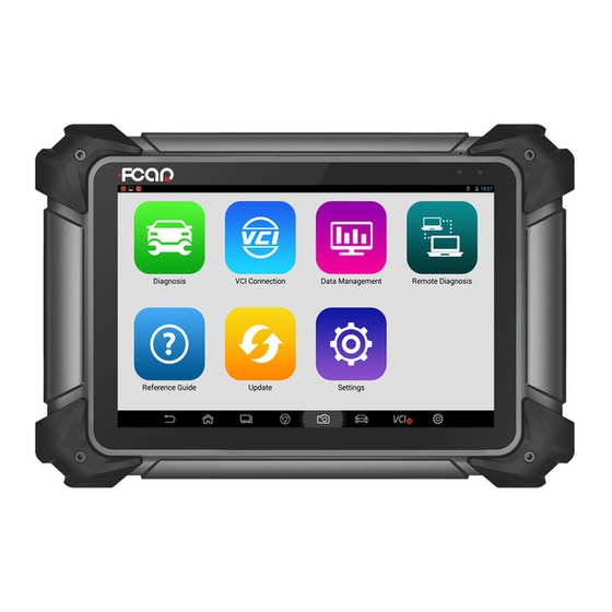
FCAR Product Manual Note: Voltage of the power supply should be within the scope of the product host. Exceeding the range may cause damage to the product. 2.2 BOOTING Press and hold the F7S host power switch (about 3 seconds) to power on host, the following welcome interface will pop up, and then system starts working. - Page 12 FCAR Product Manual Status icon: is the default icon of the standard Android operating system Toolbar (see Table 1 below ) Main menu (see Table 2 below) Guide bar (see Table 3 below) Tip: It is recommended to lock the screen whenever you are not using the device to protect your system information and save battery power.
- Page 13 For browsing and managing data files stored, see management section 4 Run this program to establish remote assistance with Remote FCAR after-sales technical team, see section 5 Provide help information such as equipment usage Reference instructions, maintenance assistance, trouble code guide inquiry, etc.
-
Page 14: Chapter Iii Vehicle Diagnosis
Website With internet connected, click it to enter FCAR official information website CHAPTER III VEHICLE DIAGNOSIS Through having established data connection with the vehicle's electronic control system... -
Page 15: Pre-Diagnostic Technical Requirements
3.1 PRE-DIAGNOSTIC TECHNICAL REQUIREMENTS 3.1.1 EQUIPMENT REQUIREMENTS F7S series automotive computer fault diagnostics is equipped with a host and various test connectors when leave factory. In testing, please select appropriate test connector according to the type of vehicle diagnosis socket. -
Page 16: Vehicle Connection
FCAR Product Manual manual; 3) Basically distinguish whether it is a mechanical fault or an electronic control fault from the vehicle fault phenomenon tested; 4) Learn about the vehicle's origin, year of production, model, engine model and more. 3.2 VEHICLE CONNECTION 3.2.1 CONNECT VCI BOX TO VEHICLE... - Page 17 FCAR Product Manual Figure 3.2-1 Connection of standard-OBD-II socket Instructions: Determine the location and the port of the diagnostic socket; Connect one end of main test cable to DB15 connector of the VCI box and fasten the fixing bolt; Connect the other end of the main test cable to the vehicle diagnostic socket;...
-
Page 18: Host And Vci Box Connection
FCAR Product Manual Figure 3.2-2 Connection of non-OBD-II interface Instructions: Determine the location, the port, and whether need to be connected to external power source of diagnostic socket; Connect one end of the main test cable to the DB15 connector of the VCI box and lock the fixing bolts;... - Page 19 FCAR Product Manual Paired through Bluetooth Turn on F7S host power supply; Select [VCI Connection] in the main menu; select [Bluetooth] in the connection mode; Click the Scan icon on the right side of the device to automatically scan Bluetooth devices nearby.
-
Page 20: Vehicle Type Selection
FCAR Product Manual from “ ” to “ ”. , indicating that the USB connection is successful, and then the vehicle diagnosis can be started. Note: These two connection methods can't be used at the same time! 3.3 VEHICLE TYPE SELECTION When all the above connections are completed, click [Diagnosis] on Main Menu to start the vehicle diagnosis. -
Page 21: Manual Vehicle Selection
VIN code Homepage Return to Main Menu Diagnostic program requires “Car Selection” before entering the system module diagnostic function. FCAR F7S series can do vehicle identification in the following ways: Manual selection Through "Auto Diagnosis" function (for gasoline models) -
Page 22: Direct Access To The Vehicle System
FCAR Product Manual The latest "Auto Vehicle Selection" function of FCAR smart diagnostic system can skip Manual Vehicle Selection, to obtain specific vehicle information directly from the vehicle ECU, and quickly enter the diagnostic interface after confirmation. At present, this function supports a few models, subject to the menu displayed. -
Page 23: Manually Input Vin Code
3.3.5 MANUALLY INPUT VIN CODE (FOR GASOLINE MODELS) For models that do not support automatic scanning of VIN codes, FCAR Diagnostic System also supports manual input of VIN codes as below: Click [VIN] function icon on Car Selection interface and select [MANUAL];... -
Page 24: Main Interface
Create test reports, you can view, print, send test reports, etc. in 'Data Management' One-click feedback, you can feedback problems in the vehicle diagnosis process to FCAR after-sales technical team 3.4.1 MAIN INTERFACE Main interface of diagnosis displays the function options of the selected models. The interface options are little different based on the different selected models. -
Page 25: Diagnosis
FCAR Product Manual fault code, erase fault code, read live data, actuation test and so on. Special function: different selected vehicle types have different special functions and the displayed function names are slightly different. This option sometimes may be displayed as special function, maintenance data, maintenance reset or other similar names. - Page 26 FCAR Product Manual One key erasure One key erase all fault codes in the system Select any system module and click OK to enter the module diagnostic interface. Click Pause, the program will automatically pause the scan Pause and display as [Continue]...
-
Page 27: Read Fault Code
FCAR Product Manual Actuation test: Carry out the module testing of specific subsystem 3.5.1 READ FAULT CODE Read and display the fault code retrieved from the vehicle system module under test and explain the fault content, as shown in Figure 3.5.1: Figure 3.5.1 Read Fault Code... -
Page 28: Read Live Data
FCAR Product Manual Fault code analysis steps: Read and record all fault codes; Erase all fault codes; Simulate the conditions generated by the fault and start a road test; Then read and record the fault code at this time; Distinguish between incidental fault codes (independent fault codes or historical fault codes) and persistent fault codes (current fault codes or associated fault codes);... - Page 29 FCAR Product Manual Figure 3.5.3-1 Read Live Data Toolbar, see Table 1 below Live data display area Hidden column, see Table 2 below Table 1 Function icon Function description Record data stream Select menu Table 2 Function icon Function description...
- Page 30 Figure 3.5.3-2 Data Stream Waveform Data stream recording and comparison function FCAR smart diagnosis system supports the recording and saving of data stream, and it can be viewed infinitely in [Data Review]. It also supports the comparison function of data streams. When the vehicle is in good condition, the data stream can be collected and stored so as to provide a data reference through the data stream comparison function for the next test or encountering a vehicle with the same model.
- Page 31 FCAR Product Manual in the pop-up window (it is suggest that the file is named after the vehicle information for easy reference), select [OK] to return; Click [OK] to start recording, manually slide the touch screen slowly to the last data column;...
-
Page 32: Actuation Test
FCAR Product Manual Figure 3.5.3-3 Data Flow Comparison 3.5.4 ACTUATION TEST By performing this function, you can access the vehicle-specific subsystem and perform component testing, when performing the actuation test, the diagnostic device inputs an instruction to the ECU to drive the actuator, and thereby determines whether the actuator of the vehicle electronic control system and its line are normal. - Page 33 Note: The control buttons will be different according to the selected test item, such as "On" "Off" or "+" "-". With the “data customization” of some models of FCAR, you can also check the working status or values of other actuators and sensors associated with the component based on actuation test, helping the service technician to find the vehicle fault more accurately and quickly.
-
Page 34: Special Function
17 special features of FCAR F7S petrol version include: Service Reset, Throttle Matching, Smart Key Matching, Odometer Calibration, Electronic Brake, Electronic... - Page 35 FCAR Product Manual Figure 3.6-1 Special Function The main interface of the adaptive operation is under the menu guide mode. Please read the screen prompts carefully and operate according to the prompts. The specific selection of the procedure will vary depending on the model tested. Here we check the general processes of adaptive operation: Select vehicle type and related configurations;...
-
Page 36: General Obdii (For Gasoline Models)
The direct access option of OBD can also be used to test all OBDII/EOBDII compatible vehicles not included in the Diagnostic System database. 3.8 DEMO ON THE FCAR F7S AND DIAGNOSTIC SOCKET CONNECTION 3.8.1 ON CONNECTING THE OBD-II CONNECTOR Choose the proper connectors according to the diagnostic connectors of the to-be-detected vehicles. -
Page 37: On Connecting The Non-Obd-Ii Connector
FCAR Product Manual shown in Figure 3.8.1-1. Figure 3.8.1-1 3.8.2 ON CONNECTING THE Non-OBD-II CONNECTOR For starters, users should confirm whether the F7S decoder’s connector matches that of the vehicle to be detected. When connecting, users should first connect the connector that is exclusive to F7S decoder to the standard OBD-II connector, and then connect the standard OBD-II connector to the main testing cable and the main unit of the decoder. - Page 38 FCAR Product Manual Jumper Holder and Jumper Introduction Introduction to a jumper holder There are 15 holes on the jumper holder, they are marked with 1, 2, 3, GND, 6, 7, 8, 9, 10, 11, 12, 13, 14, 15, VCC respectively.
- Page 39 FCAR Product Manual Common Communication Protocols Hole Number Name of the Range of Voltage Protocol Name of Jumper to Communication Line For Reference Be Connected K Line 1V lower than the Communication battery voltage CAN-H 2.5V+0.25V Communication CAN-L 2.5V-0.25V J1708-A...
- Page 40 FCAR Product Manual The method of connecting K line to the diagnostic socket and FCAR jumper holder are demonstrated in Figure 3.8.3-2. Connect the signal line to No. 7 hole, power line (battery voltage) to VCC and ground line to GND.
- Page 41 -0.25V. There might be a deviation with its value being from -0.25 to +0.25 in cases of actual measurement. Methods of connecting CAN line to the diagnostic socket and FCAR jumper holder is demonstrated in Figure 3.8.3-3 Connect CAN-H to No. 6 hole, CAN-L to No. 14 hole, power line (battery voltage) to VCC and ground line to GND.
- Page 42 Turn on the ignition switch after successfully connected everything. The power indicator light on the jumper holder will turn on. Turn on the FCAR F7S products and select proper systems for diagnosis if the diagnostic tool functions properly.
-
Page 43: Chapter Iv Data Management
FCAR Product Manual voltage of the signal line should be 1V lower than that of the battery. (if the voltage of the vehicle’s power supply is 12V, the voltage of the signal line should be about 11V±0.25V. If the power supply is 24V, the signal line’s voltage should be 23V±0.25V) -
Page 44: Chapter V Remote Diagnosis
Select [Remote] from Main Menu to enter Team Viewer interface, and then the system automatically generates and displays the device ID. Send your device ID number to FCAR after-sales team and wait for them to send the remote control request to you;... -
Page 45: Chapter Vi Reference
FCAR Product Manual CHAPTER VI REFERENCE Here we have built in product manual, FAQ, Fault Code inquiry, dictionary and other maintenance information for the user to access. CHAPTER VII UPDATE Connect F7S device to the Internet to upgrade the diagnostic software and improve product functionality in a timely manner. -
Page 46: Chapter Viii Settings
In the main menu, click [Settings] to enter the setting interface. On this interface, you can adjust following system settings: 8.1 LANGUAGE FCAR F7S series fault diagnostic equipment is available in multiple languages setting, please set according to the language supported by the model you purchased. - Page 47 FCAR Product Manual 8.2 UNIT This option allows you to set the live data unit in the diagnostic software, please select metric or British as needed. 8.3 USER INFO Set your personal information: Name, Telephone, Email, Address, etc.
- Page 48 FCAR Product Manual 8.4 SELF TEST Connect the device according to the screen icon, and click [Start Test] to check the open circuit and short circuit of the main test cable and OBD-II connector to judge whether it is good or bad.
- Page 49 FCAR Product Manual 8.6 PUSH With "Push" function, F7S host can receive periodic online messages from the server, such as system update notifications or other service message notifications. It is recommended that you always turn this function on so that you can receive the latest update service in a timely manner.
- Page 50 FCAR Product Manual 8.8 SYSTEM UPDATE This function can be used to update Android system firmware, please connect the charger before updating. 8.9 SYSTEM SETTINGS Set Android system.
-
Page 51: Chapter Ⅸ Compliance Information
FCAR Product Manual CHAPTER Ⅸ COMPLIANCE INFORMATION FCC COMPLIANCE FCC ID: 2AJDD-IDIAGSF7S2 FCC Statement This equipment has been tested and found to comply with the limits for a Class B digital device, pursuant to Part 15 of the FCC Rules. These limits are designed to provide reasonable protection against harmful interference in a residential installation. - Page 52 FCAR Product Manual Wireless base station antenna, the lower the power output. Before a new model phone is a available for sale to the public, it must be tested and certified to the FCC that it does not exceed the exposure limit established by the FCC, Tests for each phone are performed in positions and locations (e.g.
-
Page 53: Warranty Clauses
FCAR Product Manual WARRANTY CLAUSES Thank you for choosing FCAR F7S-W. In order to make the best use of the product, we recommend that you follow all recommendations for maintenance, storage, and operation in accordance with the user manual's instructions at all times. These requirements have been formulated to maximize the useful life of the product. - Page 54 8. Within the product warranty period and under this warranty clause, you can obtain free warranty service for losses due to product defects. FCAR shall not be liable for your direct or indirect loss.
- Page 55 FCAR Product Manual...
- Page 56 FCAR Product Manual...
Need help?
Do you have a question about the F7S Series and is the answer not in the manual?
Questions and answers
Здравствуйте Подскажите купил быушный Fcar f7s активировать не могу