Advertisement
Quick Links
24
22
21 11
12
Lovato
R
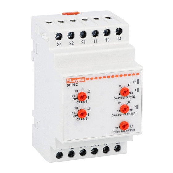
DCRM 2
1
40
20
0.5
1.5
1
2
0.15
Off
2
1
C/K step 1
Connection delay [sec]
1
20
40
0.5
1.5
3
4
0.15
2
Off
1
C/K step 2
Disconnection delay [sec]
5
3ph
System configuration
A1
A2
L1/L
L2/N S1
Schema di collegamento trifase con
inserzione mediante TA
Wiring diagram for three phase with CT
connection
L1
L2
L3
5A
480V
Step 1
Step 2
MHIT200D0207.doc
RELE' PER IL CONTROLLO
DELLA CORRENTE REATTIVA
DCRM 2
ATTENZIONE! Leggere attentamente il manuale prima
dell'utilizzo e l'installazione.
● Questi apparecchi devono essere installati da
personale qualificato, nel rispetto delle vigenti normative
impiantistiche, allo scopo di evitare danni a persone o cose.
● Prima di qualsiasi intervento, rimuovere tutte le tensioni pericolose
dall'apparecchio.
●Il costruttore non si assume responsabilità in merito alla sicurezza
elettrica in caso di utilizzo improprio del dispositivo.
● I prodotti descritti in questo documento sono suscettibili in qualsiasi
momento di evoluzioni o modifiche. Le descrizioni ed i dati a catalogo
non possono pertanto avere alcun valore contrattuale.
● Un interruttore magnetotermico va compreso nell'impianto elettrico
dell'edificio. Esso deve trovarsi in stretta vicinanza dell'apparecchio ed
essere facilmente raggiungibile da parte dell'operatore.
14
Deve essere marchiato come il dispositivo di interruzione
dell'apparecchio: IEC/ EN 61010-1 § 6.11.2.1
● Installare lo strumento in contenitore e/o quadro elettrico con grado
di protezione minimo IP40.
● Pulire lo strumento con panno morbido, non usare prodotti
abrasivi, detergenti liquidi o solventi.
ON
1
60
Descrizione
• Il DCRM2 consente di controllare la corrente
reattiva di un impianto, eliminandola dal totale
2
60
richiesto al fornitore di energia e quindi
rifasando il carico al migliore cosfi possibile.
• Esso è in grado di controllare la connessione di
1ph
max 2 banchi di condensatori.
• Ciascuno dei due banchi di condensatori può
essere abilitato singolarmente e la sua potenza
può essere definita tramite un trimmer
S2
dedicato.
• E' inoltre possibile regolare il tempo di
inserzione e disinserzione dei condensatori,
aggiustando quindi la velocità di reazione del
sistema.
• L'apparecchio è utilizzabile sia in
configurazione trifase che monofase.
Caratteristiche
• Inserzione mediante TA esterno con
secondario /5A.
• Riconoscimento automatico del senso di
collegamento del TA (diretto / inverso).
• Possibilità di abilitare singolarmente il controllo
dei due relè (Posizione OFF).
• Regolazione soglie di C/K da 0.15 a 2.00.
• Ritardo alla connessione delle capacità 1..60
sec.
• Ritardo alla disconnessione delle capacità
1..60 sec.
• Tempo di riconnessione fisso 60 sec.
L
O
• Impostazione della configurazione del sistema:
A
D
3ph / 1ph.
• Uscite a relè con contatto in scambio.
• LED verde di segnalazione alimentazione e
durata inibizione.
• 1 LED rosso di segnalazione inserzione relè 1.
• 1 LED rosso di segnalazione inserzione relè 2.
REACTIVE CURRENT
CONTROLLER RELAY
DCRM 2
safety hazards.
● Remove the dangerous voltage from the product before any
maintenance operation on it.
● Technical data and descriptions in the publication are accurate, to
the best of our knowledge, but no liabilities for errors, omissions or
contingencies arising therefrom are accepted.
●Products illustrated herein are subject to alteration and changes
without prior notice.
● A circuit breaker must be included in the electrical installation of the
building. It must be installed close by the equipment and within easy
reach of the operator.
It must be marked as the disconnecting device of the equipment:
IEC /EN 61010-1 § 6.11.2.1
● Fit the instrument in an enclosure or cabinet with minimum IP40
degree protection.
● Clean the instrument with a soft dry cloth, do not use abrasives,
liquid detergents or solvents
Description
• The DCRM2 allows to control the reactive
current of a plant, eliminating it from the total
current drawn from the mains and correcting the
cos-phi of the load to the best possible value.
• It can control the connection of maximum 2
banks of capacitors.
• Each one of the two capacitor banks can be
individually enabled and its power can be set
through a dedicated trimmer.
• It is also possible to adjust the time for
connection and disconnection of the capacitors,
modifying the reaction speed of the system.
• The device can be used both in single-phase
and three-phase wiring.
Characteristics
• Connection by external CT with 5A secondary.
• Automatic recognition of CT polarity (direct /
reverse).
• Capability to individually enable the control of
the two relays (OFF position).
• C/K threshold adjustment from 0.15 to 2.00.
• Connection delay for the steps adjustable from1
to 60 sec.
• Disconnection delay for the steps adjustable
from1 to 60 sec.
• Reconnection time fixed to 60sec.
• Selectable wiring configuration 3ph / 1ph.
• Output relays each with changeover contact.
• Green LED indictor for power on and inhibition
time.
• Red LED indicator for C/K1 tripping relay.
• Red LED indicator for C/K2 tripping relay.
17/10/2011
WARNING! Carefully read the manual before the
installation or use.
● This equipment is to be installed by qualified personnel,
complying to current standards, to avoid damages or
Page 1/6
Advertisement

Subscribe to Our Youtube Channel
Related Manuals for LOVATO ELECTRIC DCRM 2


Summary of Contents for LOVATO ELECTRIC DCRM 2
- Page 1 RELE’ PER IL CONTROLLO REACTIVE CURRENT DELLA CORRENTE REATTIVA CONTROLLER RELAY DCRM 2 DCRM 2 ATTENZIONE! Leggere attentamente il manuale prima WARNING! Carefully read the manual before the dell’utilizzo e l’installazione. installation or use. ● Questi apparecchi devono essere installati da ●...
- Page 2 Impostazioni Settings • Manopole [1] e [3] – Impostazione del C/K del • Knobs [1] and [3] – Setting of C/K ratio of the relativo step. Il C/K viene calcolato con le relevant step. The C/K ratio is calculated as seguenti formule: follows: KStep...
- Page 3 portare il cosfi al valore di 1.00). possible value (tries to drive the cos-phi as • Se gli step hanno la stessa potenza, (trimmer close as possible to 1.00) • If the steps have the same power (trimmer set impostati allo stesso valore, con tolleranza del to same value, with a tolerance of 10%) when 10%) l’apparecchio al momento connecting one step the device selects the step...
- Page 4 Schemi inserzione Wiring diagrams Connessione trifase / Three-phase connection Connessione monofase / Single-phase connection Opzione con tensione di alimentazione / misura comune Option with common supply voltage / measure voltage MHIT200D0207.doc 17/10/2011 Page 4/6...
-
Page 5: Caratteristiche Tecniche
CARATTERISTICHE TECNICHE TECHNICAL CHACTERISTICS Circuito di alimentazione Power supply circuit Dimensioni meccaniche Tensione nominale Us 220-240V ~ Rated operational voltage Us 220-240V ~ Mechanical dimensions 380-415V ~ 380-415V ~ 440-480V ~ 440-480V ~ Frequenza nominale 50/60Hz ±5% Rated frequency 50/60Hz ±5% 4.2mm Limiti di funzionamento 0,85...1,1Us... - Page 6 Contenitore Housing Esecuzione 3 moduli (DIN 43880) Version 3 modules (DIN 43880) Montaggio Guida 35mm Mounting On 35mm DIN rail (IEC/EN60715) (IEC/EN60715) oppure a vite a mezzo or by screws using clip estraibili extractible clips Materiale Poliammide Material Polyamide Grado di protezione IP40 sul fronte Degree of protection IP40 on front...
Need help?
Do you have a question about the DCRM 2 and is the answer not in the manual?
Questions and answers