Advertisement
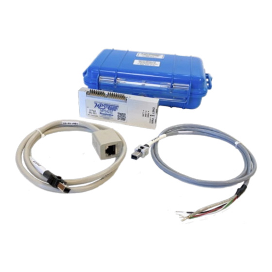
Step 1: Unpack & Inventory
When you first unpack the MPS4200, begin by inspecting
and inventorying the contents of the package. If any visible
damage is immediately noticed or if any contents are miss-
ing, contact Scanivalve before proceeding. Modules ship
standard with:
1) MPS4200 Module in case
2) Certificate of calibration
3) MPS Resource Disk (USB Drive)
5) Power Cable with flying leads
6) Ethernet Cable with female RJ45
There may be other cabling or accessories included with
your order.
Step 2: Connect Ethernet Cable
Connect the provided MPS Ethernet cable to the MPS Ether-
net port. The cable will latch into the connector.
The standard cable provides a female RJ45 connection. This
N
E
C
T
O
R
E L
A
D
S
A
P
P
R
allows for a standard RJ45 Cat5e or better Ethernet cable to
D
R
A
W
N I
G
1
5
6
0
6
2
7 -
0
connect the MPS to a Ethernet hub or switch, or directly to a
P
T
O
O
L
P
H
T
6 -
8
4 -
- 5
. S
host computer or laptop.
C
E L
A
R
H
E
A
T
S
H
R
N I
K
O
E L
N
G
T
H
=
3
E F
E
. T
Step 3: Connect Ethernet Cable
Connect the provided MPS flying leads power cable to the
MPS power port. The cable will latch into the connector. The
flying leads end can be connected to a compatible DC power
supply (5 to 36VDC @ 3.5W). See the wiring diagram on the
5
right for lead connections (Red and Black).
3
F
. T
4
3
6
1
If an AC to DC power supply is provided (PDM series), con-
5
4
nect the power cable before powering on the power supply.
Once all connections are made, apply power to the MPS and
allow the module enough time to boot. The Power, Link and
LAN lights should all light.
Step 4: Setup the Host Computer
E
R
T /
I R
G
G
E
R
C
A
B
In order to communicate withe MPS modules, the host com-
puter must be configured to be compatible with the MPS.
1 /
" 6
F
T I
2
2
1
B
The default MPS4200 IP address is:
3 /
" 2
F
T I
2
2
1
C
E L
1 /
" 0
F
T I
2
2
1
/ 1
" 4
I D
4
4
7
1
3
2
0
3
S
0 L
0
5
C
A
B
E L
4
C
1
5
6
0
6
3
2 -
C
O
N
N
E
A
T R
N
U
M
B
E
R
MPS4200 Quick Start Guide
O
I X
M
A
E T
Y L
i 3
. n
F
O
R
C
A
B
E L
C
O
N
N
E
C
N
G
R
O
U
N
D
W
R I
. E
1
CAUTION! Do not make or
break the power connector
with power applied! Doing so
risks damage to the module.
2
2
4
1
3
E L
W
F /
Y L
N I
G
E L
A
K L
H
E
A
T
S
H
R
N I
K
A
R
H
E
A
T
S
H
R
N I
K
. A
H
E
A
T
S
H
R
N I
, K
B
K L
L
O
C
I T
E T
O
N
D
2
6
A
W
G
S
H
L
D
, .
3
F
. T
C
T
O
R
S
H
E
L L
R
E
W
O
R
K
D
S E
C
R
P I
I T
O
N
R
E
V
T
O
R
A
S
E S
M
L B
. Y
-
2
3
6
8
5
7
D
S
3 (
T F
) .
D
R
A
W
N
C
H
E
C
K
E
D
6
E
N
G
N I
E E
R
5
4
M
O
3
2
A
S
E S
1
I
E T
M
C
A
D
S :
N
O
.
MPS4200 and Standard Accessories
R
E
I V
I S
D
S E
C
R
P I
I T
O
N
P
R
O
D
U
C
I T
O
N
R
E
E L
A
MPS4200 Cable Connections
+
T
R
G I
T -
R
G I
5
3 -
6
V
N I
5
3 -
6
R
T
N
MPS Flying Leads Cable Connections
S
D
A
E T
N
A
M
E
7
1 -
3
1 -
6
S
H
C
J
H
7
1 -
3
1 -
6
I T
L T
: E
7
1 -
3
1 -
6
C
J
H
M
P
S
D
L E
R
E
: V
A
I S
E Z
D
W
M
B
Y L
D
R
A
W
N I
G
A
S
C
A
L
: E
O
L
D I
W
O
R
K
S
2
0
1
6
1
5
5
6
2
5
1 -
to Ethernet
O
N
S
D
A
E T
A
P
P
R
O
to DC Power
E S
8
1 -
9
1 -
6
S
H
1
2
3
W
H
T
4
G
R
N
5
6
R
E
D
7
B
L
K
8
c
a
n
v i
a
v l
e
L
B I
E
R
T
Y
L
A
K
, E
W
A
P
O
W
E
R
T /
I R
G
G
E
R
C
A
B
W
F /
Y L
N I
G
E L
A
D
S
G
.
N
O
.
1
5
5
6
2
5
N
/
A
E
R
O
: #
A
9 -
5
3
S
H
E
T E
1
V
E
D
E L
R
E
V
-
O
F
1
Advertisement
Table of Contents

Related Manuals for Scanivalve MPS4200


Summary of Contents for Scanivalve MPS4200
- Page 1 MPS4200 Quick Start Guide Step 1: Unpack & Inventory When you first unpack the MPS4200, begin by inspecting and inventorying the contents of the package. If any visible damage is immediately noticed or if any contents are miss- ing, contact Scanivalve before proceeding. Modules ship...
- Page 2 Please consult your computer or operating system for steps on how to configure your computer’s IP address. Step 5: Access the MPS’s Web Server The MPS4200 has a single user web server which provides a simple method for communication, configuration and data collection from virtually any host computer.
Need help?
Do you have a question about the MPS4200 and is the answer not in the manual?
Questions and answers