Table of Contents
Advertisement
Quick Links
Advertisement
Table of Contents

Related Manuals for Omicron Light HUB Ultra


Summary of Contents for Omicron Light HUB Ultra
- Page 1 ...
-
Page 2: Imprint
User Manual Imprint All rights reserved. © Copyright by Omicron‐Laserage Laserprodukte GmbH Raiffeisenstrasse 5e D‐63110 Rodgau Germany Phone + 49 – (0) 6106 – 8224‐0 Fax + 49 – (0) 6106 – 8224‐10 Internet www.omicron‐laser.de E‐mail mail@omicron‐laser.de This manual or even parts of it should not be printed, copied or multiplied without permission of Omicron‐ Laserage Laserprodukte GmbH. Any kind of unauthorized reproduction, distribution or storage on disks, in whatever form and nature, constitutes an infringement of national and international copyright law and will be prosecuted. Images inside this manual may show slight deviation from the actually delivered laser system. This does not affect function or operation. Responsible for the content published: Omicron‐Laserage Laserprodukte GmbH LightHUB® is a registered Trademark of Omicron‐Laserage Laserprodukte GmbH Printed in Germany 05/2018 Version 1.0 2 ... -
Page 3: Safety Rules
User Manual Safety Rules WARNING! Read the safety precautions in this section before installing, powering, operating or servicing this product. Symbols used in this manual The following symbols are used to identify important safety information WARNING! Laser emission is possible. Assure laser safety precautions. CAUTION: Special attention to this point is necessary to meet health regulations and to avoid damage. An important note to ensure an unproblematic operation. Important safety information ... - Page 4 User Manual CLASS 3B laser product, for up to 100/500mW output‐power CLASS 4 laser product, for up to 1W output‐power The classifications are evaluated and tested under worst case conditions. Laser diode based lasers are able to output 10x higher output‐power under worst case conditions, comparing to the normal operating condition. Avoid exposure of the laser beam or stray laser light to the eyes and the skin! Be aware of the laser safety rules and pay attention to the following points: Do not look at any laser light directly or through optical lenses. Installation of a special working area for the laser is recommended, which only gives access to special trained and as far as laser safety goes, instructed persons. Warning labels have to be perceptibly placed at all entries of the area the laser is installed and running. Wherever it is possible, the beam should be sheathed by a tube, to prevent direct access to the laser beam. The working area of the laser should be shielded to prevent uncontrolled escape of the laser beam. After passing the experimental / working area the beam must ...
- Page 5 User Manual CAUTION for OEM‐usage: The LightHUB® ULTRA laser system is also available as an OEM‐product. Then it is only for usage in systems such as customer designs. Then the customer has to include the laser system in the safety‐interlock chain and main key‐control and laser‐emission indication. The OEM‐customer is responsible for a safe operation of the LightHUB® ULTRA laser CLASS 3B or CLASS 4 product. In any kind of OEM usage, the Interlock and safety shutter circuits must be evaluated and tested in the end‐use application. We will be glad to give detailed assistance to our customer, if there are any questions in safe system integration. Laser warning and explanatory labels The LightHUB® ULTRA laser system is designed as a laser class 3B or class 4 product. It complies with the rules of the IEC 60825‐1 and with FDA performance standards for laser ...
- Page 6 User Manual The following labels are fixed at the laser system next to the fibre output: 1. Laser‐warning sign (common): Size: 15 x 15mm Colour: yellow / black Location: front side, left side aperture 2. Laser‐warning and laser ray explanatory label: Class 3B: For the invisible‐range (UV): Wavelength / output power: Size: 52 x 26mm Colour: yellow / black Location: top cover, front side 375[nm] / 20[mW] 375[nm] / 70[mW] 395[nm] / 120[mW] For the visible‐range (VIS): Wavelength / output power: Size: ...
- Page 7 User Manual 488[nm] / 80[mW] 488[nm] / 100[mW] 488[nm] / 150[mW] 488[nm] / 200[mW] 505[nm] / 80[mW] 515[nm] / 20[mW] 515[nm] / 25[mW] 515[nm] / 80[mW] 515[nm] / 100[mW] 515[nm] / 150[mW] 532[nm] / 20[mW] 532[nm] / 50[mW] 532[nm] / 80[mW] 532[nm] / 100[mW] 532[nm] / 150[mW] 552[nm] / 20[mW] 552[nm] / 60[mW] 552[nm] / 80[mW] 552[nm] / 100[mW] 552[nm] / 150[mW] 561[nm] / 20[mW] 561[nm] / 50[mW] 561[nm] / 80[mW] 561[nm] / 100[mW] 561[nm] / 150[mW] 594[nm] / 20[mW] 594[nm] / 60[mW] 594[nm] / 100[mW] 633[nm] / 100[mW] 638[nm] / 40[mW] 638[nm] / 100[mW] 638[nm] / 150[mW] 638[nm] / 200[mW] 642[nm] / 140[mW] 647[nm] / 140[mW] 660[nm] / 130[mW] 685[nm] / 50[mW] ...
- Page 8 User Manual For the invisible‐range (IR): Wavelength / output power: higher than 500mW Size: 52 x 26mm Colour: yellow / black Location: top cover, front side 3. Identification of manufacturer explanatory label: Size: 46 x 26mm 63110 Rodgau, Germany Colour: silver / black Model: LightHUB ULTRA S/N: xxxxxxx Location: backside Manufactured: mm/yyyy ...
-
Page 9: Table Of Contents
User Manual Table of contents IMPRINT ............................ 2 SAFETY RULES .......................... 3 ...................... 3 YMBOLS USED IN THIS MANUAL ...................... 3 MPORTANT SAFETY INFORMATION .................... 5 ASER WARNING AND EXPLANATORY LABELS 1. INTRODUCTION ........................ 11 ® 1.1 L ULTRA ............... 11 IGHT GENERAL DESCRIPTION AND KEY FACTS 2. ... - Page 10 User Manual 6. OPTO MECHANICAL ADJUSTMENT .................. 34 ® 6.1 A ‐ ................ 34 DJUSTMENT OF THE IGHT BEAM PATH ® 6.1.1 A ................ 36 DJUSTING THE BEAM SHIFTER INSIDE THE IGHT ® 6.1.2 A .............. 37 DJUSTING THE BEAM COMBINER INSIDE THE IGHT 6.1.3 R ® .............. 38 ECOMMENDED ADJUSTMENT PROCEDURE FOR IGHT 7. ADDING LASER MODULES ....................... 41 8. TROUBLESHOOTING ....................... 44 9. ...
-
Page 11: Introduction
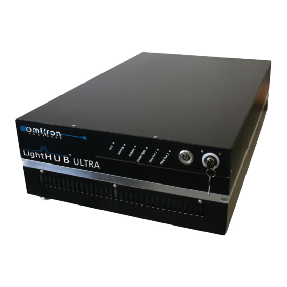
User Manual 1. Introduction ® 1.1 LightHUB ULTRA general description and key facts The LightHUB® ULTRA Compact Laser Combiner can be equipped with up to seven DPSS or diode lasers of different wavelengths in a compact and rugged design. Wavelengths between 375nm and 830nm and optical output powers up to 300mW per laser line are possible. The Compact Laser Combiners can be equipped with several types of fibres or used in free‐ space emission. Polarization maintaining fibre coupling units and non‐polarization maintaining fibres to supply the light to applications in biotechnology like confocal microscopy or flow‐cytometry and many more are possible. ... -
Page 12: Technical Data
488nm / 20mW, 60mW, 80mW, 100mW, 150mW, 200mW 515nm / 25mW, 80mW, 100mW, 150mW * 532nm / 20mW, 50mW, 80mW, 100mW, 150mW * 552nm / 20mW, 60mW, 80mW, 100mW, 150mW * 561nm / 20mW, 50mW, 80mW, 100mW, 150mW * 594nm / 20mW, 60mW, 100mW * 633nm / 100mW 638nm / 40mW, 100mW, 150mW, 200mW 642nm / 140mW 647nm / 140mW 660nm / 130mW 685nm / 50mW 705nm / 40mW 730nm / 40mW 785nm / 120mW, 200mW 808nm / 140mW 830nm / 140mW * DPSS Lasers Table 1: wavelengths and output power Please see actual wavelengths and powers on the website: www.omicron‐laser.de. Version 1.0 12 ... -
Page 13: Optical And Electro-Optical Specifications
User Manual 2.2 Optical and electro-optical specifications The LightHUB® ULTRA is consisting of up to 7 different wavelengths supported by DPSS lasers, LuxX® diode lasers, or mixed combinations. The following table shows a typical combination of two LuxX® diode lasers and one DPSS laser. Parameter Laser 1 Laser 2 Laser 3 Wavelength 488nm (+/‐ 1nm) 561nm (+/‐ 0.3nm) 638nm (‐1/+4nm) Optical output power 60mW 20mW 35mW (internal) Modulation principle direct / diode direct direct / diode Digital modulation / Laser Enable (full on / off) >150kHz >50kHz >150kHz speed Analogue modulation >1.5MHz >100kHz >1.5MHz ... -
Page 14: Operating Modes And Signal Specifications
User Manual 2.3 Operating modes and signal specifications The number of available operating modes is depending on the type of the lasers built in in the LightHUB® ULTRA. The operating modes are the same as provided from the LuxX® or DPSS lasers. Please refer to the LuxX® or DPSS laser manual for detailed explanation of its operating modes. LuxX®‐Laser operating modes available in the LightHUB® ULTRA: Mode 1 ‐ CW operation (ACC – Automatic Constant Current) Operating modes Mode 2 ‐ CW operation (APC – Automatic Power Control) Mode 3 ‐ Analogue modulation Analogue modulation > 1,5MHz input signal type 0...5V (1.2kOhm) > 150kHz (full ON/OFF) Laser enable (electronic shutter) 5V TTL (5kOhm) input signal type (available in ACC and analogue operation mode only !) Analogue < 200ns Rise‐ and falltime Laser enable < 2µs Analogue > 1000 : 1 ... -
Page 15: Dimensions And Weight
User Manual 2.4 Dimensions and weight LightHUB® ULTRA: w l h Figure 2: Dimensions of LightHUB ULTRA® 622 x 402 x 97mm³ (without fibre coupler) Dimensions (l x w x h) 622 x 402 x 182mm³ (with optional cooling unit) Approx. 22kg (depending on installed lasers) Weight Approx. 40kg (with optional cooling unit) Table 5: Dimensions and weight of LightHUB+ ULTRA® 2.5 Electrical supply and interface specifications ... -
Page 16: Options And Accessories
User Manual 2.6 Options and accessories Single mode polarization maintaining fibre FC/PC, FC/APC, FCP 8 Multi mode fibre FC/PC, FC/APC, SMA Various collimated light outputs (also on customer demand) Options & accessories Single fault condition laser safety shutter CDRH Kit (only needed for external key‐switch and interlock control) Various optical filters for narrowing the diode laser spectrum Forced air heat sink Table 7: Options and accessories Version 1.0 16 ... -
Page 17: Thermal Management And Environmental Conditions
Storage temperature: ‐20° ‐ 85°C Maximum relative humidity (non condensing): <80%; up to 30°C Operating altitude (above sea level): under 3000m Storage altitude (above sea level): up to 13000m The specified and recommended operating temperature range is 15…35°C. For the LightHUB® ULTRA laser system the heat will be dissipated through its base plate. Therefore, it is essential to provide enough heatsink at the mounting area. The total heat dissipation under worst case condition is depending on the number and type of laser heads inside the LightHUB® ULTRA. For a DPSS laser 10…15W and for a Diode laser 5…10W of heat dissipation must be calculated. Additionally, the temperature stabilization of the system needs up to 150W depending on the environmental condition. For LightHUB® ULTRA systems, the maximum number of DPSS lasers is 4. Combined with three diode lasers, totally 7 lasers are installed for calculating the worst‐case heat dissipation. The worst‐case heat dissipation will be: 4 x 15W + 30W + 150W = 240W We recommend using a heatsink with a thermal resistance of 0.05…0.06 K/W or a heatsink with a thermal resistance of 0.25…0.3 K/W with forced air cooling. When using the Omicron heatsink option, no further calculation for the required thermal resistance is needed. Version 1.0 17 ... -
Page 18: System Overview
User Manual 3. System overview Orientation of the INPUT and OUTPUT connectors at the LightHUB® ULTRA: Figure 3: LightHUB® ULTRA laser system rear view Orientation of the controls and indicators at the LightHUB® ULTRA: Figure 4: LightHUB® ULTRA laser system front view Version 1.0 18 ... -
Page 19: Status Leds
User Manual Status LEDs Interlock Emission Fibre Out Fibre Out Shutter State Error LED LED LED 1 Status Colour Red Yellow White White White White OFF OFF OFF OFF OFF OFF OFF EVICE ON /OFF OFF OFF² OFF OFF ... -
Page 20: Inside The System
User Manual 3.2 Inside the system To get access to the frame unit, open the ten cover screws and remove the top cover. After all the screws are removed, lift the top cover and disconnect the PE‐connector. Make sure to reconnect it when closing the housing. It is recommended to unplug the power supply before opening the housing cover. Figure 5: Opening the top cover of the LightHUB® ULTRA Once the housing is open see Figure 6: LightHUB® ULTRA inside view for details of the internal parts. Each laser, which is built‐in the LightHUB® frame unit, has a laser specific sub board installed on the Main PCB and a laser specific connector board on the laser side. Both boards ... - Page 21 User Manual Figure 6: LightHUB® ULTRA inside view Version 1.0 21 ...
-
Page 22: Pin Allocation And Additional Explanation
3.3 Pin allocation and additional explanation Power supply It is recommended to use the optional external power supply to operate the LightHUB® ULTRA system. In case of using an own power supply make sure to meet the specifications. 24V DC Supply Connector 4pin KYCON DC jack ‐ Cable side Function (KPPX‐4P) 1, 2 V+ in (23VDC to 25VDC), max. 13A 3, 4 GND in Ring PE Table 10: Pin allocation of 24V DC Supply Connector Communication interfaces The LightHUB® ULTRA has a built‐in USB Hub to have access to all built‐in laser modules. Use the Omicron Control Software to control and monitor all built‐in Omicron laser modules and the main controller. Use the OBIS control software to control and monitor the built‐in DPSS laser modules. Please refer to the user manuals of the lasers for further information on controlling the lasers via software or implementing communication into own software projects. Version 1.0 ... - Page 23 User Manual Control Port The Control Port gives access to the following control features over a sub‐d 15pin HD female connector. Control Port SUB‐D HD 15pol Function female 1 +5V out interlock loop (fused with polyswitch 0,2A fuse) 2 Interlock loop return 3 Key switch (Laser ON/OFF) 4 +5V out (fused with polyswitch 0,2A fuse) 5 NC 6 NC 7 NC 8 NC 9 NC 10 NC 11 Emission LED out (20mA) 12 13 Interlock LED out (20mA) 14 NC 15 GND ...
- Page 24 User Manual Key switch The LightHUB® ULTRA has one built‐in hardware key switch on the front panel and an input for an external key switch via the control port on the back panel. The signal from the front panel key switch and the signal from the control port are connected internally with a logic AND. Make sure to close the key switch loop on the control port and set the key switch on the front panel to ON‐position (I) to allow emission. The supplied interlock loop connector may be used to close the interlock loop and key switch on the control port. LED output pins The LED output pins allow the customer to add external indicators for emission, interlock and failure display. Please note that the max. output current for each pin is 20mA. The internal supply voltage for each pin is 5V. Version 1.0 24 ...
- Page 25 User Manual single component fail‐safe laser shutter system The single component fail‐safe laser shutter system is integrated in the LightHUB® housing inside the LightHUB® ULTRA. Safety is achieved by using two independent laser shutters with mutual monitoring. Please see following figure for shutter position inside the LightHUB®. Figure 7: Shutter area inside of LightHUB® The laser shutters are controlled via the connector on the back of the LightHUB® ULTRA housing. In LightHUB® ULTRA devices, Return 1 and Return 2 are internally connected together. Connect a switch between ‘send’ and one of the two ‘return’ pins. Close the switch to open the shutter, open the switch to close the shutter. Each shutter monitors its own status and the status of the second shutter. If one of the shutters detects an error condition, it blocks the laser beam and closes the second shutter as well. The following error conditions may occur: ‐ External control signal for shutter 1 unequal to external control signal for shutter 2 ‐ External control signal for shutter n unequal to feedback signal from shutter n The error condition is cleared by opening the external switch between ‘send’ and the two ‘return’ pins. ...
- Page 26 User Manual Optional Safety Shutter Connector Binder M8 4pin female – cable Function side Binder M8 4pin male 1 +3.3V send (max. 45mA) 2 Return 1 3 Return 2 4 NC Table 12: Pin allocation of Safety Shutter Connector Optional fiber switch Depending on ordered configuration a fibre switch is installed to switch laser output from fiber1 to fiber2. It is integrated in the LightHUB® housing inside the LightHUB® ULTRA. See Figure 7: Shutter area inside of LightHUB®. The fibre switch is controlled via the connector on the back of the LightHUB® ULTRA housing. Supply a 5V TTL high level to switch to fiber output 2. Leave open or supply a 0V level to switch to fibre output 1. Fibre Switch Connector SMA female Function Centre Fibre switch signal, 5V TTL (10mA max.) shield Return Table 13: Pin allocation of Fibre Switch Connector It is also possible to control the fibre switch via software. Hardware signals and software signals are connected to a logic AND. That means, if the signal is externally ...
- Page 27 User Manual Optional heat sink and fan out An optional heatsink is available for the LightHUB® ULTRA system. There is a 3pin sensor connector on the back plane to power the fans in the external heat sink. Only connect the cable from the external heat sink to the connector. FAN Out Connector Binder M8 3pin female – cable Function side Binder M8 3pin male 1,2,3 Use with optional heatsink only Table 14: Pin allocation of FAN out Connector Digital and analogue modulation The LightHUB® ULTRA system is equipped with 7 inputs from digital modulation and 7 inputs for analogue modulation of the built‐in laser modules. Modulation capabilities depend on the built‐ in laser module. Digital Modulation Connectors 1‐7 SMA female Function Centre ...
-
Page 28: Description Of Cdrh-Mode
User Manual Make sure to bring the lasers to correct operating mode via control software to enable external digital or analogue modulation. If LuxX lasers are built‐in the LightHUB® ULTRA system, the digital modulation input is routed to the laser enable input of the LuxX laser. As the digital modulation input is pulled to ground level, the LuxX lasers do not emit laser light, even when switched to CW operation. Therefore, a digital overwrite is available. Use the digital input button on the controller level to deactivate the digital input globally for all lasers. Alternatively, if the LightHUB® ULTRA housing is open, push the button on the Main PCB to toggle between digital input active and not active. ... -
Page 29: System Components
Set of mounting brackets Power Supply USB cable Remote interlock connector Laser‐control software(s) (content of the installation medium) 2 x pinhole for basic adjustment User manual (basic manual ‐ printed) For ordering spare parts, please use the above description of the sub‐part or contact your local distributor for assistance in getting the item number. 4.2 Optional parts single component failsafe laser safety shutter Beam compressor or expander optics 1 x basic tool set Forced air heat sink Optional output collimator For ordering optional parts, please use the above description of the part. Omicron can support the user by selecting the right heat sink, if required. Version 1.0 29 ... -
Page 30: Installation And Starting Into Operation
User Manual 5. Installation and starting into operation 5.1 Unpacking When you receive your LightHUB® ULTRA laser system, please immediately inspect the shipping container. If there is any damage (holes or crushing, etc.) insist that a representative of your local carrier is present while you unpack the contents. Carefully inspect your LightHUB® ULTRA laser system as you unpack it. If any damage is evident, such as dents or scratches on the covers or broken parts etc., immediately notify your carrier and your local sales distributor. For a better handling of the laser system in service matter, keep the shipping containers for sending back the laser system. If you find a damage claim, you may need them to demonstrate that the damage occurred as a result of shipping. Please check the following components which belong to the LightHUB® ULTRA laser system: 1. LightHUB® ULTRA laser system 2. -
Page 31: Installation
User Manual 5.2 Installation The LightHUB® ULTRA laser system is very easy to set up. After unpacking and inspecting, the laser system must be connected as described here: 1. Mount the LightHUB® ULTRA laser system to a suitable heat sink. There are mounting clamps supplied to mount the LightHUB® ULTRA onto an optical breadboard. Please ensure the surface of the heat sink is flat. The roughness or evenness of the mounting surface must be better than 1/10mm over the whole ground plate of the LightHUB® ULTRA. It is important to mount the LightHUB® ULTRA to an appropriate heat sink. Refer to chapter “thermal management” for further information. 2. Connect the optional CDRH remote control box or the supplied interlock connector to the control‐port. CAUTION: As standard setting for the laser system “auto‐start” and “auto‐ power” function is ON. The lasers are set to digital + analogue modulation. If CDRH mode is enabled, the lasers need a key switch toggle to start operation. 3. Connect the power supply unit or an appropriate power supply to the device. In case of using not the original power supply, make sure to meet the specified power supply demands. Version 1.0 31 ... -
Page 32: Heat Sink Installation
User Manual 5.3 Heat sink installation To connect the optional heat sink unit, place the heat sink on a table and put the LightHUB® ULTRA on top (see figure 5). Insert the three supplied stable pillar posts from the bottom side into the heat sink unit and screw the posts tight. Make sure the LightHUB® ULTRA system stays properly orientated on top of the heat sink unit. Use the 6 additional M4 screws to fix the heat sink to the LightHUB® Ultra system. After all posts are tightened, connect the cable from the heat sink unit to the fan out connector of the LightHUB® ULTRA. The supplied mounting clamps can also be used to mount the heat sink unit onto an optical breadboard. Figure 8: LightHUB® ULTRA with heat sink unit Version 1.0 32 ... -
Page 33: Starting Operation
Starting operation Use the following steps to setup the system and start operation. 1. Connect the external power supply to the LightHUB® ULTRA. 2. Connect the external power supply to the mains. 3. Connect the loopback connector to the control port or connect a customer specific circuit to close the key switch and the interlock loop. Alternatively connect the optional CDRH kit. 4. If you have an optional heatsink, make sure the cable is plugged into the Fan Out connector. 5. Push the power button on the front panel of the LightHUB® ULTRA. Key switch is off. 6. The fans should turn on and the blue backlight LED of the power button starts blinking. 7. Turn the key switch to ON position. Blue backlight LED of the power button stops blinking if system operating temperature setpoint is reached. 8. Connect a signal to the safety shutter connector or use a bridge connector to open the safety shutter. 9. Connect a logic high level to the digital modulation input and an appropriate voltage level to the analogue modulation input of a channel, which is equipped with a laser. OR Connect the system to a personal computer via USB and run Omicron Control Center software to change operating mode of the lasers to CW and deactivate digital input. WARNING! Laser emission is possible. Assure laser safety precautions. The system should emit laser light now. Version 1.0 33 ... -
Page 34: Opto Mechanical Adjustment
User Manual 6. Opto mechanical adjustment The following chapters explain the opto‐mechanical adjustment of the LightHUB® system. This should only be necessary in case of an upgrade or change in configuration. ® 6.1 Adjustment of the LightHUB beam-path To get access to the beam adjustments the frame cover of the LightHUB® system has to be removed. ATTENTION: Do not look into the beam or into reflections of the beam, when the top cover is removed! When operating the LightHUB® under open cover condition, it may emit stray‐light, which is a health hazard for the eyes and skin. Always wear appropriate protective eye‐goggles. CAUTION: Please wear gloves during the adjustment procedure to prevent hand contamination of the opto‐mechanical parts of the LightHUB®. ... - Page 35 User Manual Figure 10 shows the beam combiners and beam shifter parts in a LightHUB® as well as the direction for the alignment process as blue and yellow arrows. The following chapters explain the alignment process in detail. Beam combiner Beam shifter Adjusting screws Fixing rings Figure 10: beam shifter and combiner for LightHUB® First alignment direction of the beam combiners, no fibre connected during alignment Second alignment direction of the beam combiners, fibre connected during alignment Version 1.0 35 ...
-
Page 36: Adjusting The Beam Shifter Inside The 6.1.2 Adjusting The Beam Combiner Inside The
User Manual ® 6.1.1 Adjusting the beam shifter inside the LightHUB The beam shifter enables a centring of the laser beam on the beam combiner. The knurled knob on the beam shifter moves the beam in one axis and the rotation of the beam shifter itself rotates the shift‐axis. Therefore, an accurate positioning of the laser beam on the beam combiner is possible. Figure 11: the beam shifter positions the laser beam on the mirror ... - Page 37 User Manual ® 6.1.2 Adjusting the beam combiner inside the LightHUB The beam combiner deflects the beam in the direction of the fibre coupler unit. The horizontal and vertical position of the deflected laser beam changes by turning the hex head screws. The final position of the beam combiner can be fixed by tightening the fixing rings. Fixing rings Hex head screws Figure 13: beam combiner for LightHUB® manufactured after Jan. 2011 In order to turn the hex head screws the hex key tool as shown below can be used. Figure 14: Hex key tool (included in the shipment) for positioning of the beam combiner ...
-
Page 38: Recommended Adjustment Procedure For
User Manual 6.1.3 Recommended adjustment procedure for LightHUBs® The LightHUB® laser combiner can be equipped by various types and brands of fibre couplers. One example for a fibre coupler is the kineFLEX fibre coupler. 1. Start with the laser which is installed at the far end, away from the fibre coupler unit. Activate this laser and turn the others off. For an easier adjustment procedure, it is recommended to put in max. two additional alignment plates with a pinhole after each of the three accessible beam combiners (see Figure 15). The position of the pinholes is fixed by mounting holes (precision position). Adjust the beam shifter as it is described in chapter 6.1.1. Then adjust the beam combiner as it is described in chapter 6.1.2. The right position of the deflected beam is achieved when the beam ... - Page 39 User Manual 3. Open the mechanical shutter and place the cylindrical alignment tool into the fibre coupling unit. There is a groove at one end of the cylindrical tool. Please use first the position when the groove is positioned towards the lasers. Cylindrical alignment tool Figure 16: fibre coupling unit with cylindrical alignment tool 4. Try to adjust the laser beam with the beam combiner by turning the hex head screws (see chapter 7.1.2), so that the beam passes the 1mm pinhole of the cylindrical alignment tool with only a small power loss. Please use always the beam shifter for the first manipulation and the hex head screws at the beam combiner for the second manipulation. Please use a power meter to maximize the power through the optical beam path. Please remove the cylindrical tool and place it in the opposite direction inside the fibre coupler. The groove at the end of the tool is now positioned into the direction of the laser beam. Please adjust the fibre coupler screws only at the front position if the groove is located in the front. Adjust the fibre coupler screws at the back, if the groove is located in the back. Please realign the fibre coupler to be sure that the first laser transmits the pinholes and the cylindrical tool in both directions with maximum power. ...
- Page 40 User Manual 8. If the beam adjustments are completed, switch off all lasers, remove the alignment pinholes and place the fibre into the coupling unit. Please turn the output power of all lasers to approx. 10mW not to damage the fibre during final adjustment. Please switch on the laser close to the fibre coupler and adjust the fibre coupling unit as it is described for example in the kineFLEX operating instructions. In order to optimize the coupling, measure the laser power at the fibre ...
-
Page 41: Adding Laser Modules
The LightHUB® ULTRA can easily be upgraded by the experienced user with further laser modules. For example, if the LightHUB® is equipped with three laser modules, up to four more can be installed. In this case the upgrade kit comes contains the laser module and a beam combiner unit (factory pre‐adjusted), the corresponding optics, spacers and mounting screws. Additionally, there is a laser specific “connector board” and “sub board” as well as a ribbon cable provided to connect the laser to the main board. The wavelength setup of the LightHUB® ULTRA needs to be checked by an OMICRON service representative to make sure that it supports the desired new wavelength. The top cover must be removed to add or replace a laser. Please open the 4 top cover screws, while the system is turned OFF. ATTENTION: Do not look into the beam or into reflections of the beam, when the top cover is removed! When operating the LightHUB® ULTRA ... - Page 42 User Manual At first, please clear the space for the laser by removing the top cover seal and the (blind‐) spacer at the backside of the LightHUB®. Install the laser at the reserved position. There are precision steel positioner bolts to keep the laser in its exact intended position for the beam path. The laser must fit there with no strength during placement. Then use the four laser screws (M4 x 10mm) with star washer and washer for installing the laser head tight to the base plate. Please tighten the screws until the star washers are under strength. The beam combiner unit has also a reserved position. There are precision steel positioner bolts to keep the beam combiner unit in its intended position. There is one screw to hold the beam combiner down to the base frame. Please use the star washer and the washer with the screw for installing the beam combiner. Please tighten the screw until the star washer is under strength. Install the laser specific connector board on the back of the laser and the laser specific sub board on the reserved port of the main PCB. Fasten the main sub boards with the supplied M3 HX nuts. The DPPS laser connector board must be fixed with the supplied M2.5 screw. The Luxx laser connector boards are not fixed with screws. Connect the supplied ribbon cable between the two boards. Make sure the direction of the cable is correct. For DPSS lasers, the cable should not be twisted. For Luxx lasers refer to the following picture for explanation: ...
- Page 43 User Manual Figure 20: DPSS specific boards and connections Please turn on laser by laser now and check the output power. The new laser head should emit laser light in the pre‐aligned direction. It needs final adjustment to be launched in the fibre coupler, so please refer to the alignment procedure described in chapter 6. ATTENTION: Do not look into the beam or into reflections of the beam on surfaces while adjusting the beam to the beam path! When finished with the adjustment procedure, please put back the top cover seal in its original position. Please use the top cover screw spacers for finding the right position of the seal. After closing the top cover, please re‐check the alignment of the new added laser beam. ...
-
Page 44: Troubleshooting
User Manual Troubleshooting The errors described below are basic information to trouble shoot the LightHUB® ULTRA laser system. If additional help is required, please contact our service personnel. Error Action needed Please refer to chapter 6 and align the beam The system is used with a fibre optic and only one path. Re‐check the transmission efficiency wavelength is low in power after full adjustment. Please check the flatness of the mounting The system is used with a fibre optic and the area or if there is any contaminant between efficiency for all lines is low or the beams are not the base frame ground plate and the ... -
Page 45: Warranty
Improper or inadequate maintenance by the user Operation outside the environmental specifications of the product Wrong mounting conditions 11. Waste disposal WEEE (Waste of Electrical and Electronic Equipment) Recycling of Electronic Products, disposing of this product. In 2012 the European Union introduced regulations (WEEE – 2012/19/EG) for the collection and recycling of all waste electrical and electronic equipment. It is no longer allowable to simply throw away electrical and electronic equipment. Instead, these products must enter the recycling process. This product must not be disposed in normal garbage! When this OMICRON‐Laserage Laserprodukte product is no longer used or out of order and should be disposed please refer to the service address indicated in the scope of delivery to send back the device in its original package to the manufacturer to enter the recycling process. We thank you for your understanding! Version 1.0 45 ... - Page 46 User Manual 12. Spare parts and service (manufacturer identification) Please contact for service and spare parts: Omicron‐Laserage Laserprodukte GmbH Raiffeisenstraße 5e 63110 Rodgau, Germany E‐mail: mail@omicron‐laser.de Web: www.omicron‐laser.de Tel.: +49 (0) 6106 – 8224 ‐ 0 Fax: +49 (0) 6106 – 8224 – 10 Version 1.0 46 ...
Need help?
Do you have a question about the Light HUB Ultra and is the answer not in the manual?
Questions and answers