Thermics LUNA 2T Installation Manual
Hide thumbs
Also See for LUNA 2T:
- User manual (52 pages) ,
- Installation, technical and maintenance manual (40 pages)

Related Manuals for Thermics LUNA 2T


Summary of Contents for Thermics LUNA 2T
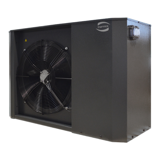
- Page 1 Installation Manual LUNA 2T Reversible heat pump with inverter technology EN-GB Translation of the Original Instructions Rev. 2.0...
- Page 2 Dear Customer, Thank you for choosing a Thermics energie machine, an innovative, modern and quality product that will ensure your well-being, silence operation and safety for a long time. This instruction manual contains important indications and suggestions that must be observed in order to make the installation and use of the machine as easy as possible.
-
Page 3: Table Of Contents
CONTENTS Introduction 1.1 Purpose of the manual 1.2 Symbols 1.3 General warnings Safety regulations 2.1 General safety rules 2.2 Security pictograms Reception and handling 3.1 Handling with packaging 3.2 Verification of packaging 3.3 Packaging content 3.4 Removing the packaging 3.5 Handling without packaging Mounting 4.1 Recommended equipment 4.2 System inspection... - Page 4 4.14 Duct characteristics Commissioning 5.1 Preliminary checks...
-
Page 5: Introduction
The manual contains information on the safety, technical aspects, operation, maintenance and transport of the following machines: LUNA 2T - Reversible heat pump with inverter technology Correct use and maintenance contribute to good operation and a longer life cycle of the machine. - Page 6 Confidentiality The technical information (texts, drawings and illustrations) contained in this manual is the property of THERMICS and must be treated as confidential. It is strictly forbidden to disclose, reproduce or translate, even partially, this document without the written permission of THERMICS.
-
Page 7: Symbols
Symbols For the safety of persons and property, a special symbol has been used in this documentation to allow readers to focus on hazardous conditions, warnings or relevant information: DANGER! PAY UTMOST ATTENTION TO THE TEXT BLOCKS MARKED WITH THIS SYMBOL. Danger with risk of injury or death. -
Page 8: General Warnings
General warnings 1.3.1 Allowed use • Please read this booklet carefully. • The documentation supplied with the unit must be handed over to the owner who must keep it carefully for future maintenance or servicing. • The company shall not be liable for any damage to persons, animals or property arising from installation, adjustment and maintenance mistakes, improper use or a partial or superficial reading of the information provided herein;... - Page 9 1.3.3 User information • Keep this manual and the wiring diagram in a place accessible to the operator. • Note down the unit's identification data so as to provide it to the service centre in the event of a service request (see section "Machine identification"). •...
-
Page 10: Safety Regulations
Safety regulations DANGER! The machine has been designed and built according to appropriate safety standards. Before using the machine, carefully follow all the precautions and instructions provided in the manual to avoid accidents. General safety rules The use of products that use electricity and water involves compliance with certain basic safety rules such as the ones provided below: •... -
Page 11: Security Pictograms
Security pictograms 1 Electricity hazard 2 Sharp object hazard... -
Page 12: Reception And Handling
Reception and handling Handling with packaging The machine is supplied on wooden pallets protected by cardboard packaging. WARNING! Use spacers to avoid damaging the machine . WARNING! The machine is supplied with the vibration dampers already installed; handle the units carefully to avoid damaging them. - Page 13 Lifting with forks • Insert the forks from the side so as not to damage the panels. Lifting with crane • Position the lifting belts as shown in the figure.
-
Page 14: Verification Of Packaging
Verification of packaging Before accepting the received goods, please check that: • the machine has not been damaged during transportation; • the material delivered corresponds to that indicated on the transport document by comparing the data with the packing plate. In case of damage or faults: •... -
Page 15: Packaging Content
Packaging content he sTandard supply includes Heat pump Technical documentation WARNING! Keep the manual in a dry place, to avoid deterioration, for at least 10 years for future reference. -
Page 16: Removing The Packaging
Removing the packaging • Cut the fixing straps. • Remove the top part by lifting it upwards. • Remove any protective inserts. • Remove the transparent film that wraps the machine. -
Page 17: Handling Without Packaging
Handling without packaging Use handling equipment suitable for the machine weight. DANGER! The unit is supplied with the vibration dampers already installed; handle the unit carefully to avoid damaging them. DANGER! Use spacers to prevent damage to the unit. -
Page 18: Mounting
Mounting Recommended equipment To install the machine it is advisable to use the following equipment: • set of cross-head and slotted screwdrivers; • cutting nippers; • scissors; • set of open end wrenches and pipe wrenches; • ladder; • hydraulic material for sealing the threads; •... -
Page 19: System Inspection
System inspection DANGER! Current regulations require the heating system to be inspected before commissioning. The inspection must be carried out by a qualified technician. Fill in the following check list on the installation data: ysTem Description Notes Signature Date □ Washed system □... -
Page 20: Verification Of Functional Spaces
The installation of the machine must allow specialised and authorised personnel to easily perform maintenance activities while respecting both the safety distances between the units and the other equipment and the technical spaces indicated in the table. LUNA 2T 6 kW 2T MB 2000 LUNA 2T 8 kW 2T MB... -
Page 21: Unit Positioning
Unit positioning The vibration dampers (1) are supplied fully screwed in. • To adjust the height of the vibration dampers (1) turn counterclockwise (A) to raise the angle. DANGER! Check that the table supports the machine weight. -
Page 22: Noise Control
Noise control During installation, take into account the effect that the position of the machine will have on the noise emitted. Position the machine as far away from walls as possible. The noise level increases according to the place of installation as illustrated below: Module positioned against a wall: +3 dB(A) Module positioned in a corner: +6 dB(A) Module positioned in a confined indoor space: +9 dB(A) -
Page 23: Recommendations And Suggestions
Recommendations and suggestions In order to limit acoustic disturbances and vibrations, we suggest that you do the following: • Install the module outdoors on a metal frame or on an inertia base. The weight of this base must be at least twice the weight of the module. •... -
Page 24: Access To Internal Parts
Access to internal parts DANGER! Before removing the side panels, make the hydraulic connections. DANGER! When removing the Control Panel dashboard, pay attention to the connection cable. To access the internal parts, remove the panel of the concerned area (A-B): •... - Page 25 • if necessary, remove the upper panel (3) by loosening its retaining screws; • disengage the panel (2) by sliding it outwards;...
- Page 26 • remove the panel (4) of the electrical panel (5) by loosening the screws (6).
-
Page 27: Hydraulic Diagrams
Hydraulic diagrams System side hydraulic connections ey To hydraulic connecTions Connections by the manufacturer System flow Connections by the installer System return line ey To hydraulic connecTions Vent valve Safety valve Expansion vessel Temperature probe Shut-off cock 10 Discharge Mesh filter 11 Differential pressure switch Drain cock 12 Circulation pump... -
Page 28: Machine Connections
4.10 Machine connections System outlet System inlet Cable glands Condensate drain... - Page 29 Cooling capacity correction factor • cQ: Flow rate correction factor • cdp: Pressure drop correction factor 4.10.2 Example of connection diagram LUNA 2T 2 pipes Mixer V.E. Heat. Utilities Double accumulation DHW + Technical Cold water inlet V.E. DHW...
-
Page 30: Hydraulic Connection
A minimum available water volume of 8 litres per size number is recommended. conditions. For example for LUNA 2T 8 litres x 10 = 80 litres WARNING! Pipes must be discharged before the heat pump is connected so that any type of contaminant does not damage the components. - Page 31 4.11.4 Water quality - recommendations In order to maintain the functionality and durability of the internal components as well as the performance of the unit, please follow the recommendations below. Firstly, you should try to prevent corrosion, which is a complex process that depends on the interaction of the different materials with the various chemicals dissolved in the water.
- Page 32 It is also recommended that you follow the guidelines outlined in standard VDI 2035 "Guideline for the prevention of damage in water heating installations" designed to prevent the presence of oxygen in the water. • Keeping the pH within the limits indicated above prevents the formation of magnetite. It is recommended to use chemical inhibitors suitable for this purpose.
-
Page 33: Connecting The Condensate Drain
4.12 Connecting the condensate drain The condensate water tank (1) collects and eliminates most of the condensate water produced by the heat pump (2). WARNING! For the heat pump to function, the condensate water must be regularly removed and the condensate water drain must be correctly positioned so as not to damage the house. - Page 34 4.12.1 Condensation water diversion • If the house has a cellar, the stone box (3) must be positioned so that the condensate water does not affect the house. Alternatively, the stone box (3) can be placed directly under the heat pump (2). •...
- Page 35 4.12.3 Drain into the gutter pipe • The outlet of the condensate water pipe (4) must be located at a depth protected from frost. • Direct the tube downwards. • The condensate water pipe (4) must be equipped with a siphon (5) to prevent air circulation inside the pipe.
-
Page 36: Power Supply Connection
4.13 Power supply connection • Connect the cable to the terminals inside the electrical panel by passing it through the appropriate cable glands located on the lower part of the panel. • Refer to the attached wiring diagrams for connections. •... - Page 37 Check the connections, the main voltage and the phase voltage before starting the machine to avoid damage to the electronics of the air/water heat pump. 4.13.1 Connections LUNA 2T 06 - LUNA 2T 08 - LUNA 2T 10 onnecTions Connector B...
- Page 38 use proTecTion Terminal blocK Fan protection fuse Protection fuse for system circuit circulator Auxiliary circuit protection fuse 230 V Auxiliary circuit protection fuse 230 V Auxiliary circuit protection fuse 230 V Auxiliary circuit protection fuse 24 V ser Terminal blocK Unit power connections NC: Alternative system water source enable NO: Alternative system water source enable...
- Page 39 4.13.2 LUNA 2T 12 - LUNA 2T 14 - LUNA 2T 16 onnecTions Connector B A2 - Compressor inverter Connector C QM1- Compressor thermal-magnetic Connector D circuit breaker Fuse terminal blocks (FU1...FU6) User terminal blocks Connector A...
- Page 40 use proTecTion Terminal blocK Fan protection fuse Protection fuse for system circuit circulator Auxiliary circuit protection fuse 230 V Auxiliary circuit protection fuse 230 V Auxiliary circuit protection fuse 230 V Auxiliary circuit protection fuse 24 V ser Terminal blocK Unit power connections NC: Alternative system water source enable NO: Alternative system water source enable...
- Page 41 4.14 Duct characteristics Gas separator System circulator Compressor 4-way valve Temperature probe Liquid receiver Pressure transducer Dehydrator filter Filling valve Electronic expansion valve High pressure switch Finned heat exchanger System heat exchanger...
- Page 42 Commissioning Preliminary checks • Check the availability of diagrams and manuals of the installed machine. • Check the availability of wiring and hydraulic diagrams of the system to which the machine is connected. • Make sure the machine is placed on a perfectly level surface. •...
- Page 44 Registered Office and Operational Headquarters: Via C. Pascoletti 2 - 33040 Povoletto (UD) Italy Tel. (+39) 0432 823600 – Fax. (+39) 0432 825847 www.thermics-energie.it | info@thermics-energie.it All rights reserved. Thermics Energie reserves the right to modify and update this document...
Need help?
Do you have a question about the LUNA 2T and is the answer not in the manual?
Questions and answers