Thermics LUNA 2T User Manual
Hide thumbs
Also See for LUNA 2T:
- Installation manual (44 pages) ,
- Installation, technical and maintenance manual (40 pages)

Related Manuals for Thermics LUNA 2T


Summary of Contents for Thermics LUNA 2T
- Page 1 User terminal manual LUNA 2T Reversible heat pump with inverter technology EN-GB Translation of the Original Instructions Rev. 2.0...
- Page 2 Dear Customer, Thank you for choosing a Thermics energie machine, an innovative, modern and quality product that will ensure your well-being, silence operation and safety for a long time. This instruction manual contains important indications and suggestions that must be observed in order to make the installation and use of the machine as easy as possible.
-
Page 3: Table Of Contents
CONTENTS 1.1 Control panel 1.2 Display 1.3 Access levels 1.4 Procedures 1.5 Parameter list: User menu 1.6 Parameter list: programming menu 1.7 Alarms and signals 1.8 Alarm Log 1.9 Resetting the alarms 1.10 Alarm list... -
Page 4: Use
Control panel The control panel consists of a display and programming keys. It illuminates in the presence of alarm states. Alarms Press the button to display the type of alarm or to reset it. Allows you to access the programming pages or read the Programming parameters. -
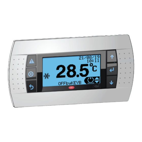
Page 5: Display
Display ii / ii / ii ii : ii -28.9 °C SET2 OFFbyALRM isplay Description Operating information Shortcut menu ON-OFF unit menu. Setpoint setting and setpoint 2 activation menu. Operating mode change menu: heating, cooling and domestic hot water only. Unit information display. - Page 6 isplay Description Operating modes (heating, cooling and DHW). Operation in DHW production mode. Operation in system heating mode. Operation in system cooling mode. Operation in DHW priority in heating mode. Operation in DHW priority in cooling mode. Defrost function active. Drip function active.
-
Page 7: Access Levels
Access levels It has 3 consultation and programming levels: ccess levels To start/stop the unit, program the setpoints, activate/deactivate the most common functions, Without password change the season and refer to the active setpoints and the main temperatures detected. To check the unit's programming, change With User password (Default: “2345”) date and time, activate a time, daily, annual programming and make some simple settings. -
Page 8: Procedures
Procedures 1.4.1 Machine start-up The machine must be started up for the first time by personnel authorised by the manufacturer. Set the QF main differential switch located outside the machine to the OFF position. Set any remote ON/OFF switch to OFF. Remove the front panel first, then the electrical panel. - Page 9 1.4.4 Starting Press the keys to select the ON/OFF menu. Press the key to select ON (1). Press the key to return to the main page. Press the key to move to the "operating mode" menu. Use the keys to select the desired operating mode: summer, winter and DHW only.
- Page 10 1.4.6 Switching off Press the keys to select the ON/OFF menu. Press the key. Press the keys to move to OFF. Press to confirm. 1.4.7 Setting the setpoints Press the keys to select the "setpoint settings" menu. Press to confirm. The "Qb01"(3) screen displays the winter setpoints "Set"...
- Page 11 1.4.8 Boost coil activation (optional) Press the keys to select the "coil" menu (4). Press the key. Press the key to select ON. 21/08/19 10:28 28.9 °C OFFbyKEYB 1.4.9 Boost coil deactivation (optional) Press the keys to select the "coil" menu. Press the key.
- Page 12 Press the key to change the month and then the year. Move the cursor back to the "time" field by pressing Press the keys to change the hour. Press the key to change the "minutes" field. Press the key again to move the cursor to the screen header line where you can select other items from the "programming"...
- Page 13 1.4.14 Program activation System program: Press the key. Enter the user password (see paragraph “1.4.3 Entering the password”). Press the key to enter the "programming" menu. Press the keys to select "I. Time Program” Menu "Fc001": Press the key to enter the "Fc001" menu. Press the key again to move the cursor to the time program enable parameter for the "Heating/Cooling"...
- Page 14 1.4.15 Enabling the Supplementary Source On the control panel: The “PROGRAMMING” button can be used to access the programming menu after entering the Service password. Buttons can be used to select the first number of the password, after confirming by pressing the button, you can move to the second number and so on until reaching the fourth.
- Page 15 INTEGRATION S Heater D0004 User Integration Thresh.: 20.0°C Diff.: 2.0°C 175s Delay: perating moDe escription external probe value for boiler switch on THRESH (recommended value 7°C) hysteresis threshold between the operation of one generator DIFF and another (recommended value 3.0°C) DELAY boiler activation delay (recommended value 180s) IMPORTANT...
- Page 16 Intervention parameters for distance from the setpoint Screen for setting the operating mode of the warning due to an excessive divergence from the setpoint that activates the supplementary source. S Heater D0008 Low water temp.alarm Mng.type: Ext.Temp.Active Setpoint offset: 5.0°C Startup: 30min Run:...
- Page 17 The following parameters are available: perating moDe escription The supplementary source is activated to carry out the LEGIONELLA disinfection cycle. The supplementary source is activated in addition to the heat INTEGRATION pump to produce DHW The heat pump switches off and the supplementary source is SUBSTITUTION activated The supplementary source takes over from the heat pump as it...
- Page 18 SUBSTITUTION S Heater D0018 DHW Substitution Thresh.: -15.0°C Diff.: 5.0°C perating moDe escription external probe value for switching on (recommended value THRESH 5°C) hysteresis threshold between switching on and off DIFF (recommended heat 3°C) IMPORTANT Pages D0019 and D0020 display the parameters for managing the circulator and requests.
- Page 19 Intervention parameters for distance from the setpoint On this screen, we can set the operating mode of the warning due to an excessive divergence from the setpoint that activates the supplementary source, where: S Heater D0022 Low water temp.alarm Mng. type: Ext.
- Page 20 1.4.16 Enabling the heating or cooling curve On the control panel: The “PROGRAMMING” button can be used to access the programming menu after entering the Service password. Buttons can be used to select the first number of the password, after confirming by pressing the button, you can move to the second number and so on until reaching the fourth.
- Page 21 Heating curve S Plant Aa025 HP set compens. (ExtT X) (PlantT Y) X1: -10.0°C Y1: 56.0°C X2: -5.0°C Y2: 50.1°C X3: 2.0°C Y3: 46.0°C X4: 10.0°C Y4: 46.5°C This menu can be used to set the heating curves for winter operation. WARNING! This menu appears only if the setting explained in point 5 is enabled RECOMMENDED VALUES...
- Page 22 • In combination with aluminium radiators Ref. Display description U.M. Default Default °C X1: -25.0 Y1: 40.0 °C X2: 10.0 Y2: 40.0 Aa025 HP set compens. °C X3: 20.0 Y3: 20.0 °C X4: 45.0 Y4: 20.0 IMPORTANT The Y4 value and the summer setpoint are linked; modifying one also modifies the other. Please note that: •...
- Page 23 RECOMMENDED VALUES • Direct zone with outdoor probe Ref. Display description U.M. Default Default °C X1: -25.0 Y1: 12.0 °C X2: 25.0 Y2: 12.0 Aa024 CH set compens. °C X3: 35.0 Y3: 7.0 °C X4: 50.0 Y4: 7.0 • Mixed zone with outdoor probe Ref.
- Page 24 1.4.17 Logout After entering a password (user password or maintainer password) you can exit the programming change status with the "logout" function. Press the key. Enter the password (see paragraph “1.4.3 Entering the password”). Press the key to enter the "programming" menu. Press the keys to select "L.
-
Page 25: Parameter List: User Menu
Parameter list: User menu u.m. isplay Description eFault Qa001 Unit Power On/Off System heating setpoint System heating standard setpoint °C 30.0 10.0 50.0 Qb01 System heating setpoint 2 °C 35.5 10.0 50.0 DHW setpoint DHW standard setpoint °C 48.0 10.0 55.0 Qb02 DHW setpoint 2... -
Page 26: Parameter List: Programming Menu
Parameter list: programming menu 1.6.1 Adjustment u.m. D isplay Description eFault System System pump operating hours 999999 Maintenance hour threshold (in thousands) Aa001 Reset of system pump hour count System pump request 999.9 -999.9 Inverter system pump manual mode Minimum setpoint temperature in cooling °C 10.0 999.9... - Page 27 u.m. D isplay Description eFault Enabling start PID control Adjustment water temperature °C 999.9 -999.9 System adjustment request 100.0 -100.0 Aa009 Start PID proportional band °C 12.0 999.9 Start PID integral time Sec. 65535 Start PID derivative time Sec. Enabling operation PID control Adjustment water temperature °C 999.9...
- Page 28 u.m. D isplay Description eFault Enabling compressor start by advanced FALSE antifreeze request Advanced antifreeze setpoint (with unit °C -999.9 AFreezeSetP off) Advanced antifreeze differential (with °C 15.0 99.9 unit off) Aa022 Maximum duration of the AFreezeHeat_Adv condition (in Min. minutes) Time interval between two consecutive AFreezeHeat_Adv conditions (in...
- Page 29 u.m. D isplay Description eFault Enable function TRUE Units Defines the User circulator control type: - TEMP + USER ON: Circulator active with system request active and water temperature close to the setpoint. - ON UNIT ON: Circulator active with Unit ON and water temperature close Aa027 to the setpoint.
- Page 30 u.m. D isplay Description eFault Minimum temperature setpoint in DHW °C 10.0 999.9 -99.9 mode Ab005 Maximum setpoint temperatures in LowLimMskSet °C 55.0 999.9 DHW mode Enabling DHW setpoint compensation Ab006 FALSE function DHW start flow alarm delay Sec. Ab008 DHW operation flow alarm delay Sec.
- Page 31 u.m. D isplay Description eFault Qc002 System circuit information Qc003 DHW circuit information Qc005 Cooling circuit information Qc006 Compressor status Qc009 Electronic expansion valve status Qc010 Source information Qc011 Defrosting information Qc018 System supplementary source status Qc019 DHW supplementary source status Qc020 System program status DHW programme status Qc021...
- Page 32 1.6.4 Coil u.m. isplay Description eFault System coil D0001 Enabled FALSE Off differential °C Supplementary source operating hours 999999 Maintenance warning threshold Hour counter reset No Units D0002 Activation status No Units Manual request (0: None; 1: Man Off; No Units 2: Man On) D0003 Function enabling No Units...
- Page 33 u.m. isplay Description eFault Legionella cycle start time - hours Legionella cycle start time - minutes D0014 Legionella cycle end time - hours Legionella cycle end time - minutes Days of the week No Units Legionella cycle start time - hours Legionella cycle start time - minutes Legionella cycle end time - hours D0015...
- Page 34 u.m. isplay Description eFault Source Fan management (0=Independent; TRUE 1=Common) Fan operating hours 999999 Fan maintenance threshold E0003 Fan inverter request Fan operating hour counter reset 100.0 Fan inverter manual mode Reference temperature threshold for -5.0 -999.9 999.9 cold climates Minimum fan speed in cooling mode 10.0 100.0...
- Page 35 u.m. isplay Description eFault Inverter fan minimum speed 20.0 100.0 Inverter fan maximum speed 100.0 100.0 E0024 Fan acceleration time Maximum forcing activation offset -99.9 99.9 0: None; 1: Temp. Evap.; 2: Outdoor temperature; 3: Evap. Temp. & Press. Defrost warning based on evaporation E0026 temperature Defrost warning based on outdoor...
- Page 36 u.m. isplay Description eFault E0037 Page reserved for maintenance users and manufacturer. E0038 Page reserved for maintenance users and manufacturer. E0039 Page reserved for maintenance users and manufacturer. E0040 Page reserved for maintenance users and manufacturer. E0044 Page reserved for maintenance users and manufacturer. E0045 Page reserved for maintenance users and manufacturer.
- Page 37 isplay Description eFault Enable Summer / Winter contact Fa020 Enable contact system request Enable On/Off from BMS Enable operating mode from BMS Fa021 Enable system request from BMS Enable DHW request from BMS 1.6.6 Alarms (Events) This field is also available after pressing the button.
- Page 38 1.6.7 Settings u.m. isplay Description eFault Date and Time Date format (0: DDMMYY; 1: MMDDYY; 2: YYMMDDD) mont Month Year Ha001 Hour Minutes Min. Seconds 1 - Monday; 2 -Tuesday; 3 - Wednesday; 4 - Thursday; 5 - Friday; 6 - Saturday;...
-
Page 39: Alarms And Signals
Alarms and signals 1.7.1 Alarm indication LEDs The red LED under the button may be: • Off: no active alarm. • Flashing: at least one active alarm. • On: at least one active alarm and the display shows an alarm mask. 1.7.2 Alarm masks Pressing the... - Page 40 the mask shows the alarm code (3) in ascending order. Each alarm contains the information necessary to understand the possible causes of the problem: ∙ alarm number / total alarms (4); ∙ alarm code (3); ∙ date and time of alarm activation (5); ∙...
-
Page 41: Alarm Log
Alarm Log From the main menu, by entering the "Alarm history" menu you can access the following alarm log display mask: Data logger Record: 01 AL173 09:28 15/05/15 Circuit 1 HP alarm by pressure switch Start Event: 20.18 Condensing t. 26.04 Discharge t. -
Page 42: Alarm List
1.10 Alarm list escription FFects AL000 Unit - Prototype operation alarm Auto reset Unit switching off AL001 Unit - Remote conn. alarm User reset Unit switching off AL002 Unit - Permanent memory writing error User reset Information purpose only AL003 Unit - Memory writing error User reset Information purpose only... - Page 43 escription FFects Auto reset up AL026 Unit - DHW circuit flow failure alarm (if any) to 8 times in DHW circuit switching off one hour AL027 Unit - DHW pump overload User reset DHW circuit switching off AL028 Unit - External coil temperature alarm (if any) Auto reset Information purpose only Unit - System circuit antifreeze alarm in cooling...
- Page 44 escription FFects Auto reset up AL107 Cooling circuit 1 EVD - Low overheating to 3 times in Circuit 1 switching off one hour AL108 Cooling circuit 1 EVD - LOP Auto reset Circuit 1 switching off AL109 Cooling circuit 1 EVD - MOP Auto reset Circuit 1 switching off Cooling circuit 1 EVD - High condensate...
- Page 45 escription FFects AL144 Cooling circuit 1 Inverter - PFC undervoltage Auto reset Power+ switching off AL145 Cooling circuit 1 Inverter - High pressure alarm Auto reset Power+ switching off AL146 Cooling circuit 1 Inverter - High pressure alarm Auto reset Power+ switching off Cooling circuit 1 Inverter - Reference voltage AL147...
- Page 46 escription FFects AL191 Cooling circuit 2 - High pressure sensor alarm Auto reset Circuit 2 switching off AL192 Cooling circuit 2 - Low pressure sensor alarm Auto reset Circuit 2 switching off Cooling circuit 2 - Discharge temperature probe AL193 Auto reset Circuit 2 switching off alarm...
- Page 47 escription FFects AL220 Cooling circuit 2 Inverter - Offline Auto reset Power+ switching off AL221 Cooling circuit 2 Inverter - Overcurrent Auto reset Power+ switching off AL222 Cooling circuit 2 Inverter - Motor overload Auto reset Power+ switching off AL223 Cooling circuit 2 Inverter - DC Bus overvoltage Auto reset Power+ switching off...
- Page 48 escription FFects Auto reset up Cooling circuit 2 - Evaporation temperature AL254 to 3 times in Circuit 2 switching off antifreeze alarm one hour AL255 Cooling circuit 2 - Compressor 1 maintenance Auto reset Information purpose only Cooling circuit 2 - Compressor 2 maintenance AL256 Auto reset Information purpose only...
- Page 49 escription FFects Cooling circuit 1 Power+ AL319 Cooling circuit 1 - Safety alarm 112 Auto reset switching off Cooling circuit 1 Power+ AL320 Cooling circuit 1 - Safety alarm 113 Auto reset switching off Cooling circuit 1 Power+ AL321 Cooling circuit 1 - Safety alarm 114 Auto reset switching off Cooling circuit 1 Power+...
- Page 50 escription FFects Cooling circuit 2 Power+ AL343 Cooling circuit 2 - Safety alarm 104 Auto reset switching off Cooling circuit 2 Power+ AL344 Cooling circuit 2 - Safety alarm 105 Auto reset switching off Cooling circuit 2 Power+ AL345 Cooling circuit 2 - Safety alarm 106 Auto reset switching off Cooling circuit 2 Power+...
- Page 51 escription FFects Cooling circuit 2 Power+ AL367 Cooling circuit 2 - Safety alarm 212 Auto reset switching off Cooling circuit 2 Power+ AL368 Cooling circuit 2 - Safety alarm 213 Auto reset switching off Cooling circuit 2 Power+ AL369 Cooling circuit 2 - Safety alarm 214 Auto reset switching off Cooling circuit 2 Power+...
- Page 52 Registered Office and Operational Headquarters: Via C. Pascoletti 2 - 33040 Povoletto (UD) Italy Tel. (+39) 0432 823600 – Fax. (+39) 0432 825847 www.thermics-energie.it | info@thermics-energie.it All rights reserved. Thermics Energie reserves the right to modify and update this document...
Need help?
Do you have a question about the LUNA 2T and is the answer not in the manual?
Questions and answers