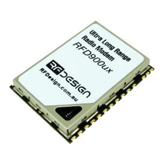
Summary of Contents for RFDesign RFD900ux
- Page 1 RFD900ux Radio Modem Series Hardware User Manual 902-928MHz frequency band...
- Page 2 RFD900ux Data Sheet www.rfdesign.com.au General Cautions During operation there must be a separation distance of 20cm between all persons and the antenna. Ensure that all used RF connectors are secure and properly terminated. When used in the US - FCC Caution Caution: The user is cautioned that changes or modifications not expressly approved by the party responsible for compliance could void the user's authority to operate the equipment.
-
Page 3: Table Of Contents
RFD900ux Data Sheet www.rfdesign.com.au Table of contents Key features ............................ 3 Specifications ..........................4 OEM Labelling ..........................5 Output power levels........................6 Performance characteristics ......................7 Pin signals and layout ........................9 Recommended PCB Design ......................11 Physical dimensions ........................12 Diversity ............................ -
Page 4: Key Features
• USB interface Compliances and Worldwide Acceptances: The RFD900ux is designed to be compliant to AS4268:2012, and FCC 15.247. It has not been certified as a standalone modem and should be compliance tested in the final product. Last update 12/09/2019... -
Page 5: Specifications
RFD900ux Data Sheet www.rfdesign.com.au Specifications Performance Supported RF Data Rates 12, 56, 64, 100, 125, 200, 224, 500 and 750kbps Indoor Range 500m – 1km Line-Of-Sight Range 40km or more depending on antennas Transmit Power 0 to 30dBm in 1dBm steps... -
Page 6: Oem Labelling
RFD900ux Data Sheet www.rfdesign.com.au 3 OEM Labelling For equipment containing the RFD-900x where the RFD-900x label is not visible the following applies. Equipment using the RFD 900x in the USA must display a label referring to the enclosed module. This label must contain the words “Contains FCC ID: 2ADLE-900X”. -
Page 7: Output Power Levels
Many countries have different legal power levels. Be sure to operate within the legal power limits of the country that you are operating in. The RFD900ux modem can support the power levels between 0dBm and 30dBm in 1dBm steps. Formula 2-1 can be used to convert the power in dBm into milliwatts. -
Page 8: Performance Characteristics
RFD900ux Data Sheet www.rfdesign.com.au Performance characteristics Figure 4-1 shows how the output power of the RFD900ux varies with supply voltage when the output power is set to +30dBm. 29.6 29.4 29.2 28.8 28.6 28.4 28.2 Supply Voltage (Vcc) Figure 4-1: Output power vs. input supply voltage Figure 4-2 shows how the current through the RFD900ux varies with the transmit power level. - Page 9 RFD900ux Data Sheet www.rfdesign.com.au The table below is used to determine the sensitivity of the RFD900ux according to the selected air data rate. The link budget is directly affected by the sensitivity, and therefore the communication range also varies. The sensitivity values in the table are based on a 10 BER.
-
Page 10: Pin Signals And Layout
RFD900ux Data Sheet www.rfdesign.com.au Pin signals and layout Figure 5-1: Physical pin layout of the RFD900ux Radio Modem Pin # Name Direction Description Max Voltage VUSB Input Power supply from USB USB_DM USB Data - USB_DP USB Data + SWO_EXT... - Page 11 RFD900ux Data Sheet www.rfdesign.com.au SIRX_EXT Input UART Data In 3.3V SITX_EXT Output UART Data Out 3.3V SIRTS_EXT Output Request to send 3.3V SICTS_EXT Input UART Clear to send 3.3V Ground Ground In case there is a need to force the modem into boot mode, pull the SWO pin to the ground while applying power.
-
Page 12: Recommended Pcb Design
RFD900ux Data Sheet www.rfdesign.com.au Recommended PCB Design Symbol Dimension (mm) Symbol Dimension (mm) 11.5 21.2 Last update 12/09/2019... -
Page 13: Physical Dimensions
RFD900ux Data Sheet www.rfdesign.com.au Physical dimensions Last update 12/09/2019... -
Page 14: Diversity
Diversity The RFD900ux has two antenna ports and firmware which supports diversity operation of antennas. During the receive sequence the modem will check both antennas and select the antenna with the best receive signal. The antenna selected during receive is then also used for subsequent transmission. -
Page 15: Pcb Design Guidelines
10 PCB Design Guidelines Some guidelines must be followed as to ensure the PCB design meets the RFD900ux thermal dissipation and electromagnetic compatibility requirements. The proposed layout can be used as a starting point and it is not guaranteed to comply with EM immunity and emissions regulations as is. -
Page 16: Useful Links
RFD900ux Data Sheet www.rfdesign.com.au 11 Useful links RFD900ux Firmware The RFD900x runs the same firmware as all other radios from the RFD900x family. http://files.rfdesign.com.au/firmware/ RFD SiK firmware is standard SiK (open source) RFD Multipoint firmware is multipoint SiK (MP SiK) RFD900x Flash Programmer http://files.rfdesign.com.au/tools/... -
Page 17: Document Revision History
RFD900ux Data Sheet www.rfdesign.com.au 12 Document revision history Version Date Changes 20/08/2019 Release document 12/09/2019 Amended VBUS pin voltage Last update 12/09/2019...


Need help?
Do you have a question about the RFD900ux and is the answer not in the manual?
Questions and answers