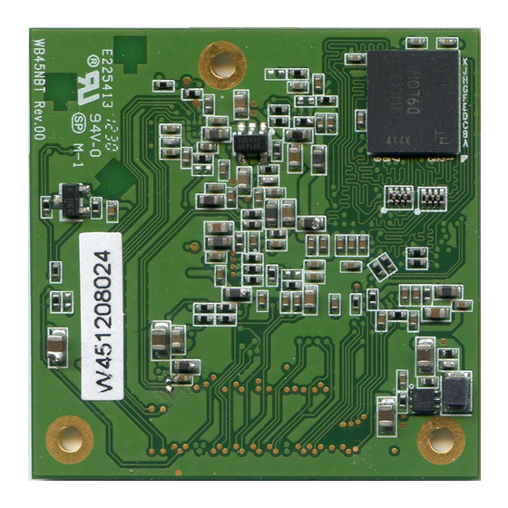
Summary of Contents for Laird WB45NBT
- Page 1 Quick Start Guide Laird WB45NBT Version 1.2 Americas: +1-800-492-2320 Option 2 Europe: +44-1628-858-940 Hong Kong: +852-2923-0610 www.lairdtech.com/wifi...
- Page 2 Change Description Approval 22 July 2014 Initial Release Andrew Chen 21 Nov 2014 Removed paragraph on Starting WebLCM from the Laird CLI Andrew Chen 7 July 2015 Added Note on No Serial Communication Steve DeRosier Embedded Wireless Solutions Support Center: Laird Technologies http://ews-support.lairdtech.com...
-
Page 3: Table Of Contents
Laird WB45NBT WB45NBT Quick Start Guide ONTENTS Introduction to the Laird WB45NBT ......................4 Product Description ............................. 4 Quick Start Guide – WB45NBT ........................5 Inventory of Equipment ..........................5 Additional Required Tools .......................... 5 Hardware Installation and Configuration ....................5 Basics of the BB45NBT Board ........................ -
Page 4: Introduction To The Laird Wb45Nbt
802.11i/WPA2 Enterprise authentication, data encryption, and BT protocol stacks. The WB45NBT is a fully integrated module with RF shielding and three U.FL type antenna connectors. The Main antenna (for Wi-Fi) and the Auxiliary antenna (for Bluetooth) work separately to get the best coexistence performance. -
Page 5: Quick Start Guide - Wb45Nbt
To assemble the WB45NBT evaluation kit, follow these steps: 1. Attach the standoffs to the underside of the BB45NBT board. 2. Connect the 2 U.FL coax cables to the 2 U.FL connecters on the underside of the WB45NBT board. Figure 1 shows the location of the Wi-Fi and Bluetooth antennas. - Page 6 BB45NBT Breakout board. Ensure that the 2 U.FL cables and SMA connectors are passed through the aperture in the BB45NBT board. 4. Using the small Philips head jeweler’s screw driver, secure the WB45NBT using the 3 small Philips screws to the BB45NBT board.
- Page 7 Laird WB45NBT WB45NBT Quick Start Guide USB Power Port RED LED - D20 Power Switch DC Jack Figure 2: Alternative power sources WB45NBT 80-Pin Connector BT Antenna Hole Ethernet Jack IRQ/SW1 Button Reset Button Wi-Fi USB power Antenna Hole port...
-
Page 8: Basics Of The Bb45Nbt Board
BB45NBT overview diagram Figure 4. To send commands to the WB45NBT you will need to download and set up a terminal emulator, such as Putty or TeraTerm, on your host. Note that a variety of emulators are available. To download and set up TeraTerm, follow these steps: 1. - Page 9 Figure 2) to either the From DC Jack or From USB Power Port to match your chosen method of powering the BB45NBT board to apply power to the WB45NBT. The Red LED D20 will light on the BB45NBT board. Wait until the WB45NBT has completed booting and you see the prompt:...
-
Page 10: Laird Cli Basics
DTIM: 0 The WB45NBT defaults to start in AP mode. This allows the user to associate and attach to the WB45NBT as one would a normal access point and use the integrated Laird WebLCM tool to configure the WB45NBT. The Status line highlighted in yellow above shows that the WB45NBT is operating in AP mode. -
Page 11: Configuring The Wb45Nbt With Weblcm
#. Configuring the WB45NBT with WebLCM Once the WB45NBT is operating in AP mode, you may configure the WB45NBT using the WebLCM tool. To configure the device, complete the following steps: 1. Associate your computer with the WB45NBT by scanning the available Wi-Fi access points in your area. -
Page 12: Wb45Nbt File System
5. Click the Wifi tab to display the profiles page. Here, you may add your required Wi-Fi profiles. 6. When you have added a profile or profiles to the WB45NBT, you must select a profile to make active. Select the desired profile from your list and click Activate. The profile will now be active when AP mode is disabled. - Page 13 Laird WB45NBT WB45NBT Quick Start Guide /etc/init.d/opt/ optional startup scripts Create a symlink to the item to be started: # ln -s /etc/init.d/opt/<name-of- script> /etc/init.d /etc/ssl default wifi certificate location DO NOT put your certificates in for all certificates /etc/ssl/certs directory /lib/firmware/ath6k/AR6003/hw2.1.1...


Need help?
Do you have a question about the WB45NBT and is the answer not in the manual?
Questions and answers