
Related Manuals for Laird WB40NBT


Summary of Contents for Laird WB40NBT
- Page 1 WB40NBT Quick Start Guide Version 2.0 Americas : +1-800-492-2320 Europe : +44-1628-858-940 Hong Kong : +852-2923-0610 Embedded Wireless Solutions Support Center: http://ews-support.lairdtech.com www.lairdtech.com/wireless...
-
Page 2: Revision History
Quick Start Guide SDC-WB40NBT EVISION ISTORY Revision Date Description Approved By 21 March Initial version Eric Bentley 2012 2 Feb 2012 Reworked for BB rev 2 board Eric Bentley Reworked for BB rev 3 board, general edits, 6 Feb 2015 Eric Bentley new photos. -
Page 3: Table Of Contents
Hardware Installation and Configuration ....................4 Basics of the BB40NBT Board............................ 6 Host Software Installation and Initial Communication with the BB40NBT ............... 7 Laird CLI Basics ................................9 WB40NBT File System ............................... 9 Additional Documentation ........................10 Embedded Wireless Solutions Support Center: Americas: +1-800-492-2320 http://ews-support.lairdtech.com... -
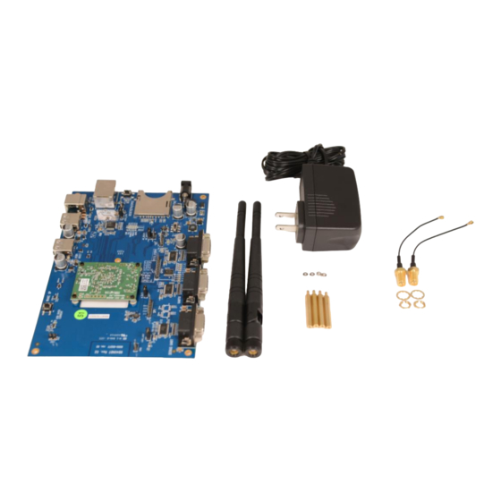
Page 4: Inventory Of Equipment
Attach the four riser assembly mounting screws onto the breakout board. These screws are installed from the bottom of the breakout board. Connect the 2 U.FL coax cables to the SDC-WB40NBT (the bottom of the smaller central board). Connect the SMA end to an antenna. - Page 5 Quick Start Guide SDC-WB40NBT Figure 1: Antenna Cable Connections (Rev 3 boards only) – Mount the antennae in the antenna holes on the BB40NBT rev 3 board. Use the Antenna nut and washer to secure the antennae. Note: (Rev 2 boards do not have antenna mounting holes) Connect the Antennae to the SMA connectors.
-
Page 6: Basics Of The Bb40Nbt Board
Figure 3: Power Supply Connection Basics of the BB40NBT Board The Laird WB40NBT is a flexible communications module providing a variety of interfaces which are made available on the BB49NBT. Additional information regarding all interfaces and their usage and configuration is available in the WB40 Reference Manual. -
Page 7: Host Software Installation And Initial Communication With The Bb40Nbt
Connect the DB9 connector of your USB-to-RS232 cable to the port marked Debug UART shown in Figure To send commands to the WB40NBT you will need to download and set up a terminal emulator, such as Putty or TeraTerm, on your host. Note that a variety of emulators are available. - Page 8 USB-to-RS232 cable you are using: e.g. . Remember this COM port number. Set the serial port’s settings to match the WB40NBT’s communications protocol. To adjust settings, navigate to Setup > Serial port. Adjust the settings (as needed) according to the following: Port Must match the COM port of your USB-to-RS232 cable.
-
Page 9: Laird Cli Basics
The Laird CLI provides a command line interface to control the Wi-Fi features of the WB40NBT. The Linux shell prompt is represented by the “#” symbol. From the prompt, enter sdc_cli to start the Laird CLI. When the Laird CLI starts, the prompt will change to “sdc#”. -
Page 10: Additional Documentation
Various firmware files for the WB40 wifi and BT radios DDITIONAL OCUMENTATION For more in depth documentation about the WB40NBT, including Hardware Integration Guide, Application Notes, and more, visit the documentation tab of the WB40NBT product page at lairdtech.com Embedded Wireless Solutions Support Center: Americas: +1-800-492-2320 http://ews-support.lairdtech.com...
Need help?
Do you have a question about the WB40NBT and is the answer not in the manual?
Questions and answers