Table of Contents
Advertisement
Quick Links
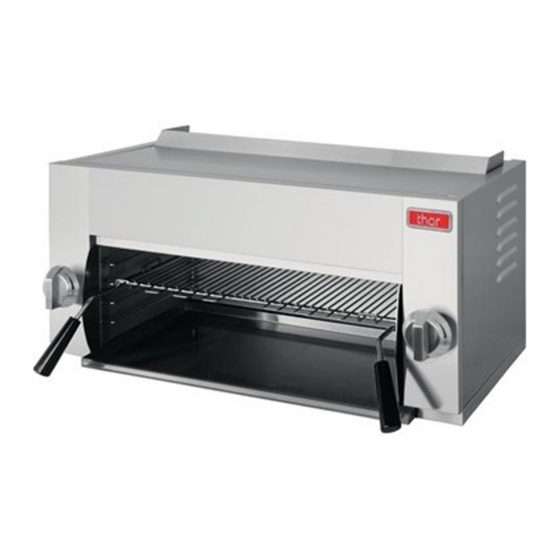
Thor Gas Salamander
Installation and Operation Instructions
Model: GE559-N GE559-P
Please complete this information and retain this manual for the life of the equipment. For Warranty
Service and/or parts, this information is required.
Model Number
WARNING: For your safety, do not store or use gasoline or other flammable vapors or
liquids in the vicinity of this or any other appliances. Keep the area free and clear of
combustible.
WARNING : Improper installation, adjustment, alteration, service or maintenance can
cause property damage, injury, or death. Read the installation operating and maintenance
instructions thoroughly before installing, or servicing this equipment.
WARNING:Instructions must be posted in a prominent location. All safety precautions
must be taken in the event the user smells gas. Safety information can be obtained from
your local gas supplier.
IMPORTANT FOR FUTURE REFERENCE
Serial Number
15 Badgally Road, Campbelltown
Thor after sales/service: 1300 225 960
NSW 2560
Date Purchased
Advertisement
Table of Contents

Related Manuals for THOR GE559-N


Summary of Contents for THOR GE559-N
- Page 1 WARNING:Instructions must be posted in a prominent location. All safety precautions must be taken in the event the user smells gas. Safety information can be obtained from your local gas supplier. 15 Badgally Road, Campbelltown NSW 2560 Thor after sales/service: 1300 225 960...
-
Page 2: Table Of Contents
Contents Introduction ..................... 2 Specifications ................... 3 General Pack Contents Gas Supply Requirements Dimensions ....................4 Installation ....................5-9 Installation Requirements Unpacking Location Clearances Assembly Gas Connection Commissioning Operation ....................10-11 Operation Guide Description of Controls Lighting the Main Burner Main burner air supply Cleaning and Maintenance ................12 Initial cleaning Daily Cleaning... -
Page 3: Introduction
Introduction We are confident that you will be delighted with your Thor Gas Salamander, and it will become a most valued appliance in your commercial kitchen. To ensure you receive the utmost benefit from your new Gas Salamander, there are two important things you can do. -
Page 4: Specifications
Specifications General Commercial gas salamander. Pack Contents The following is included: Thor Gas Salamander 1pcs racks 4pcs Feet (optional) Instruction Manual Wall Mounting Bracket, including: -2 x 25mm Black Plastic Spacer. -2 x 3/8” Bolts/Nuts -6x 30mm Screw Tox. -
Page 5: Dimensions
Dimensions Dimensions for Gas Salamander Minimum clearance from grease filter - minimum 600mm - Refer AS/NZS5601 - Gas Installations Note: Gas Salamander rack can carry a load of up to: 15KG (33 lbf) -
Page 6: Installation
Installation Installation Requirements NOTE: • It is most important that this appliance is installed correctly and that operation is correct before use. Installation shall comply with local gas, health and safety requirements. • This appliance shall be installed with sufficient ventilation to prevent the occurrence of unacceptable concentrations of substances harmful to health. - Page 7 Installation (continued) Assembly NOTE: • This appliance is assembled before delivery except feet and rack. • This appliance is fitted with adjustable feet to enable the appliance to be positioned securely and level. This should be carried out on completion of the gas connection. Refer to the ‘Gas Connection’...
-
Page 8: Clearances
Installation (continued) Clearances NOTE: Only non-combustible materials can be used in close proximity to this appliance. Combustible Surface Non Combustible Surface Left / Right Hand Side 100mm 25mm* 30mm Rear 50mm Top Clearance to: 200mm Extraction Hood 600mm Grease Arresting Filter** 750mm Ceiling*** We recommend allowing a clearance of 100 mm on either side of the... - Page 9 Installation (Continued) Wall Mounting (To Non-Combustible Wall Only) Fig. 1 1. Fix the wall mounting bracket to the wall with six screws, in such a position that the top of the bracket is level and at least 945 mm (38”) above any surface beneath the unit.
-
Page 10: Gas Connection
Gas Connection NOTE: ALL GAS FITTING MUST ONLY BE CARRIED OUT BY AN AUTHORISED PERSON. The Gas Salamanders do not require an electrical connection, as they function totally on the gas supply only. It is essential that the gas supply is correct for the appliance to be installed and that adequate supply pressure and volume are available. -
Page 11: Operation
Operation Operation Guide CAUTION: • THIS APPLIANCE IS FOR PROFESSIONAL USE AND IS ONLY TO BE USED BY QUALIFIED PEOPLE. • ONLY QUALIFIED SERVICE PERSONS ARE TO CARRY OUT INSTALLATION, SERVICING OR GAS CONVERSION OPERATIONS. • COMPONENTS HAVING ADJUSTMENTS PROTECTED (E.G. PAINT SEALED) BY THE MANUFACTURER SHOULD NOT BE ADJUSTED BY THE USER/OPERATOR. - Page 12 Operation (Continued) CAUTION The space between the legs at the bottom admits combustion air. DO NOT BLOCK THIS SPACE. Do not permit fans to blow directly at the unit. Wherever possible, avoid open windows next to the units' sides or back. Avoid wall type fans which create air cross-currents within a room. It is also necessary that sufficient air should be allowed to enter the room to compensate for the amount of air removed by any ventilating system.
-
Page 13: Cleaning And Maintenance
Cleaning and Maintenance INITIAL CLEANING: Prior to operating your new salamander, thoroughly wash the exterior with a mild detergent or soap solution. Do not use abrasive cleaners, since this might damage the cabinet finish. If the stainless steel surfaces become discolored, scrub by rubbing only in the direction of the finished grain. -
Page 14: Adjustments
Replace the burner injectors. See the parts list or Gas Specification Table below. Adjust the gas supply pressure, and convert the gas regulator. Change rating label, warning label, GAS SPECIFICATION TABLE Natural Gas Propane ULPG GE559-N GE559-P GE559-P Single burner Heat 16MJ/Hr 16 MJ/Hr... -
Page 15: Troubleshooting
TROUBLESHOOTING Consult the following table: Problem Cause Remedy Ensure that the main gas supply to the unit is Main gas supply to unit is “OFF” “ON” Ensure that the gas line has enough gas Not enough gas pressure. pressure. Ensure that the gas tanks are not empty. -
Page 16: Explosion Drawing
Explosion drawing... - Page 17 Explosion drawing(Continued)...
-
Page 18: Spare Parts List
Spare Parts List CODE Part No DESCRIPTION GE559-P GE559-N Rack 01.11.1062056 Rack support 01.02.1005371 Left insulation 01.15.1066413 Side panel-l 01.05.1029292 Left inner panel 01.15.1066420 Upper left plate 01.05.1029296 Burner protect 01.03.1015100 Upper inner2 01.15.1066419 Burner protect connector 01.05.1029298 Upper inner1 01.15.1066418... - Page 19 Spare Parts List CODE DESCRIPTION Part No GE559-P GE559-N Front insulation 01.15.1066416 Front cover 01.05.1029294 Control panel-l 01.05.1029293 Main pipe assembly 06.05.1472745 L-connector 01.18.1067451 Main burner injector/Orifice 01.20.1068670 (for Natural Gas) - #185 Main burner injector/Orifice 01.20.1068671 (for LPG) - #109 Infrared burner 01.03.1015139...
- Page 20 15 Badgally Road, Campbelltown NSW 2560 Thor after sales/service: 1300 225 960 V1.Rev4 12-20...
Need help?
Do you have a question about the GE559-N and is the answer not in the manual?
Questions and answers