Advertisement
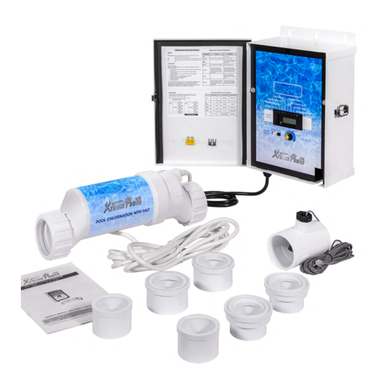
SALT WATER SYSTEM CHLORINATOR
ITEM: 90151 / 90152 / 90153
OWNER'S MANUAL AND SAFETY INSTRUCTIONS
SAVE THIS MANUAL: KEEP THIS MANUAL FOR SAFETY WARNINGS, PRECAUTIONS, ASSEMBLY,
OPERATING, INSPECTION, MAINTENANCE AND CLEANING PROCEDURES. WRITE THE PRODUCT'S
SERIAL NUMBER ON THE BACK OF THE MANUAL NEAR THE ASSEMBLY DIAGRAM (OR MONTH
AND YEAR OF PURCHASE IF PRODUCT HAS NO NUMBER)
FOR QUESTIONS PLEASE CALL OUR CUSTOMER SUPPORT: 909.628.0880 MON-FRI 9AM TO 3PM PST
Advertisement

Related Manuals for XtremepowerUS 90151

Summary of Contents for XtremepowerUS 90151
- Page 1 SALT WATER SYSTEM CHLORINATOR ITEM: 90151 / 90152 / 90153 OWNER’S MANUAL AND SAFETY INSTRUCTIONS SAVE THIS MANUAL: KEEP THIS MANUAL FOR SAFETY WARNINGS, PRECAUTIONS, ASSEMBLY, OPERATING, INSPECTION, MAINTENANCE AND CLEANING PROCEDURES. WRITE THE PRODUCT’S SERIAL NUMBER ON THE BACK OF THE MANUAL NEAR THE ASSEMBLY DIAGRAM (OR MONTH AND YEAR OF PURCHASE IF PRODUCT HAS NO NUMBER) FOR QUESTIONS PLEASE CALL OUR CUSTOMER SUPPORT: 909.628.0880 MON-FRI 9AM TO 3PM PST...
- Page 2 IMPORTANT SAFETY INFORMATION GENERAL SAFETY WARNINGS Read all safety warnings and instructions. Failure to follow the warnings and instructions may result in electric shock, fire and/or serious injury. Save all warnings and instructions for future reference. SAFETY The warnings, precautions, and instructions discussed in this instruction manual cannot cover all possible conditions and situations that may occur.
-
Page 3: Table Of Contents
TABLE OF CONTENTS 1. General Instruction 3 2. Warning And Safety Instructions 4 3. Function And Operation Instructions 4. Daily Usage and Maintenance 5. Trouble Shooting 6 6. Parameter Table 7 7. Explosion View And Parts List... -
Page 4: General Instruction
GENERAL INSTRUCTION The chlorine generator is an automatic chlorine generation system for pool sanitation. The operation requires a low concentration of salt (sodium chloride) in the pool water. The chlorine generator automatically sanitizes your pool by converting the salt into free chlorine which kills bacteria and algae in the water. Chlorine will revert back to sodium chloride after killing bacteria. -
Page 5: Warning And Safety Instructions
WARNING AND SAFETY INSTRUCTIONS • WARNING ‒ Electrical Hazard. Failure to follow instructions can result in serious injury or death. • WARNING ‒ Disconnect this product from the main power supply completely before servicing the swimming pool equipment. • WARNING ‒ Be certain the product is only plugged into a protected outlet that is protected from short-circuits. - Page 6 FUNCTION AND OPERATION INSTRUCTIONS Operation Mode 1. Super chlorination mode:In any mode, press "S" button to enter, the super chlorination mode will automatically return to the original chlorination mode after running for 24 hours, and press "S" button again to exit the super chlorination mode.
- Page 7 CONTROL PANEL Salinity / Temperature /Status Display Super chlorination mode Insufficient water flow error indication light Super chlorination mode light Water temperature error indication light Salinity error indication light Operating indication light Salinity level display Shutdown/function select button Power on/ function select button Salinity Display Button Instructions: Power on/ off Function selecting In standby status, press "MORE/ON" for the Salt producing time increase: press "MORE/ON" first time to turn on the generator, and press button when machine is on Salt producing time "LESS/OFF" for the first time to turn off the decrease: press "LESS/OFF" for first time, the generator, and it will show as "STOP". machine will be off, and press again Automatic cleaning mode Super chlorination mode Keep pressing "MORE" for a while to enter the Whenever in any mode, press 'S' to enter Super self-cleaning mode when starting up, and chlorination mode continue to press "MORE" or "LESS" to adjust...
-
Page 8: Daily Usage And Maintenance
Contents for the LED screen Display character Meaning Display character Meaning The chlorine generator is Current salinity level (ppm) open Current water temperature The chlorine generator is detected, the default is ℃, closed Automatic cleaning mode Error alarm and the setting, the number corresponding error light is represents the self-cleaning in red interval hour The chlorine generator is in suspension The chlorine generator alternates between chlorination producing and suspension, and takes one hour as a cycle. For example, when it is 60%, there are 36 minutes in chlorination producing status, and the rest 24 minutes are in suspension. DAILY USAGE AND MAINTENANCE Salinity regulation The salt in the pool is constantly recycled and the loss of salt is smaller than during the entire swimming season. - Page 9 POUNDS and (Kg) OF SALT NEEDED FOR 3200 PPM Gallons and liters of Pool/Spa water Current salt 6000 Level 8000 10000 12000 14000 16000 18000 20000 22000 24000 26000 28000 30000 32000 34000 36000 38000 40000 (22700) (30000) (37500) (45000) (52500) (60000) (67500) (75000) (82500) (90000) (97500) (105000) (112500) (120000) (127500) (135000) (142500) (150000)
- Page 10 Maintain and clean chlorine generator electrolytic cell Before taking out the electrolytic cell, disconnect the power supply of chlorine generator. After removal, check whether there is scaling (light-colored hard skin or flaky sediment) between titanium plates and some debris stuck on the electrode plate of the electrolytic cell. ...
-
Page 11: Troubleshooting
Error code Possible Reasons troubleshooting A conductive metal is embedded in the Cut off the power supply, remove the chlorine titanium plates generator and rinse the titanium plate Err1 Load short circuit Check whether the wiring position of titanium There is a short circuit of water inlet at the plate is flooded or burnt out. If not drain out of connection of titanium plates water, re-install and start the equipment Very low salinity, no current or very little Add a small amount of salt water to the cells and current restart the chlorine generator Cut off the power supply, remove the chlorine The wire connecting the titanium plate fall Err2 Load break generator, and check whether the titanium plate off wiring is off The titanium plate is very old Change electrolytic cell Salinity is higher than the maximum limit Err3 Change part of the pool water to reduce salinity specified - Expel air from the cells, ensuring that the water Salinity is lower than the maximum lim it surface exceeds 2 / 3 of the cells Err4 specified - Add salt to the pool The water temperature detected is ... -
Page 12: Parameter Table
PARAMETER TABLE Model 7018 70189 70190 Input Power 115V 115V 115V Output Power 24V Max. Electricity 6.5A current Chlorine producing Amount 87g 120g 179g 3400PPM,24h Working temperature Air temperature 0-50℃,water temperature11℃-45℃ Union Type US US US Flow Switch Type External External External Min. water flow to /h /h /h start the machine ... - Page 13 DISCLAIMER PLEASE READ THE FOLLOWING CAREFULLY THE MANUFACTURER AND/OR DISTRIBUTOR HAS PROVIDED THE PARTS LIST AND ASSEMBLY DIAGRAM IN THIS MANUAL AS A REFERENCE TOOL ONLY. NEITHER THE MANUFACTURER OR DISTRIBUTOR MAKES ANY REPRESENTATION OR WARRANTY OF ANY KIND TO THE BUYER THAT HE OR SHE IS QUALIFIED TO MAKE ANY REPAIRS TO THE PRODUCT, OR THAT HE OR SHE IS QUALIFIED TO REPLACE ANY PARTS OF THE PRODUCT.
Need help?
Do you have a question about the 90151 and is the answer not in the manual?
Questions and answers
my unit is 2 months old, it has read high salt since I got it, goes from anywhere between 4600-5700 ppm. I know my salt level is 3700. I don't really know what else to do. I have been in contact with your company and was told it self calibrates but its not and has never yet produced chlorine, I really need some help solving this. Thank you
If the XtremepowerUS 90151 unit consistently reads high salt levels and does not produce chlorine, it means the salinity is higher than the maximum limit (above 4800 PPM), causing the chlorine generator to stop (ERR4 fault). To fix this, replace part of the pool water to lower the salt level.
This answer is automatically generated
Have a !e up on screen with a600 Salt level
Where can I find a better guide to hooking up the electric inside my meter box? I can't believe there are no detailed instructions with this product!