
Related Manuals for Blohm + Voss Oil Tools FloorHand 9GF-1102


Summary of Contents for Blohm + Voss Oil Tools FloorHand 9GF-1102
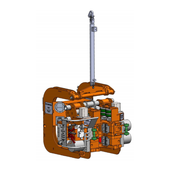
- Page 1 Blohm + Voss Oil Tools, LLC 9GF-1102 Cantilever Style FloorHand with 9FM-2050 Hydraulic Lift Technical Documentation To be used with Serial Numbers 200+...
- Page 2 GENERAL INFORMATION Warnings and Notes information contained herein. and specifications without CE Marking WARNING: A “WARNING” Blohm + Voss Oil Tools, LLC, announcement. INDICATES A DEFINITE The tool complies with will not be held liable for The values specified in...
- Page 3 Safety issues WARNING: ONE SHOULD WARNING: FAILURE TO NOT RE-USE THEM. ALWAYS WARNING: ALWAYS USE AVOID CREATING IGNITION CONDUCT ROUTINE REPLACE THEM WITH NEW LIFTING APPARATUS SOURCES, LIKE HEAT, AS A MAINTENANCE COULD SAFETY ELEMENTS. (SLINGS, CABLES, RESULT OF THE USE OF THE RESULT IN EQUIPMENT SHACKLES AND THE TOOL WITH OTHER TOOLS...
-
Page 4: Table Of Contents
TABLE OF CONTENTS TABLE OF CONTENTS DESCRIPTION General Components Wrenches Spinner Frame Controls Lift Cylinder Specifications Hydraulic Requirements Shipping Data (Approximately allowing for crate or pallet) COMMISSIONING FloorHand Commissioning Procedure INSTALLATION Normal Rig Move Removal and Installation Lifting Attaching to the Lift Cylinder Locating the HPU and attaching the Hydraulic Lines Attaching the Hydraulic Lines Make Up Torque Adjustment... - Page 5 Hydraulic System Inspection Dismantling Inspection Check Category I (Ongoing Observation) Check List Category II (Daily) Check List Category III (Every Year) Check List Category IV (Every 2 years) Inspection Categories acc. to API RP 8B Periodic Inspection Inspection Check Lists SPARE PARTS Recommended Spare Parts for One Year Operation DRAWINGS...
-
Page 6: Description
DESCRIPTION... -
Page 7: General Components
General Components The Blohm + Voss Oil Tools, LLC FloorHand is a combination torquing and spinning tool designed for quick installation on a variety of drilling rigs. This manual covers the basic FloorHand 9GF-1102 including the 9FM-2050 Hydraulic Lift Cylinder. -
Page 8: Lift Cylinder
Lift Cylinder The Blohm + Voss Oil Tools, LLC Lift Cylinder 9FM-2050) provides working stroke length of the 36” (91.4 cm). The rated pressure for the cylinder is 3,000 psi (20,684.27 kPa. The cylinder has a maximum extend capacity of 4,915 lbs (415.91 kgs) and a maximum retracting capacity of 9,420 lbs (4,272.73 kgs) at 3,000 psi (20,684.27 kPa. -
Page 9: Specifications
Specifications Hydraulic Requirements 2,800 psi (19.30 MPa) - 193 bar Hydraulic supply pressure (max.) 2,500 psi (17.23 MPa) - 172 bar Hydraulic supply pressure (min.) 23 - 28 gpm (87 - 106 lpm) Hydraulic flow rate required 1” hose with 3/4” MNPT at FloorHand end Supply connection (min.) 1 1/4”... - Page 10 (2,581 mm) 101.6 in (1,174 mm) 46.2 in (1,352 mm) (1,488 mm) 53.2 in 58.6 in Figure 2...
-
Page 12: Commissioning
COMMISSIONING... - Page 13 Approved: Suppiler References: Procurement References: TAG NO: Date: Signature: SDRL Code: Area: System: Pages: Encl: Company: Document Title/ Equipment: Commissioning Check Sheet for FloorHand (Iron Roughneck) Rig/Vessle/Customer Order: Equipment Serial No: Supplier: Document No: Blohm + Voss Oil Tools, LLC...
-
Page 14: Floorhand Commissioning Procedure
___ Without pipe, clamp and unclamp spinner 10 times, check for leaks. Note: spinner may, or may not close evenly, this is normal. ___ Back torque adjustment knob out completely, then turn in (clockwise) 4 turns, Blohm + Voss Oil Tools, LLC. ___ Actuate torque cylinder 10 complete strokes in each direction, check for leaks. ___ Adjust make up speed flow control for a 5 second stroke. Verify during commissioning. - Page 15 ___ Set Pressure Release Valve (PRV) output to obtain 600 psi at lower clamp cylinder. Verify during commissioning. 17. ___ Clamp upper wrench, ensure that system pressure is now present on lower clamp cylinders also (PRV reading should not change), unclamp upper wrench, unclamp lower wrench. ___ Mock up test pipe, with torque, at end of stroke, check that gauge dump valve functions correctly. ___ Stall spinner in make direction and hold for 5 seconds, check for leaks. ___ Stall spinner in break direction and hold for 5 seconds, check for leaks. 21. ___ Operate manipulator / lift cylinder full up & down 10 times to remove all air from cylinder and counterbalance valve, check for leaks. If commissioning, inform rig crew that this should be done after every rig-up. ___ Raise manipulator / lift cylinder to mid stroke, check that counterbalance valve holds. ___ If applicable, extend and retract manipulator full out and in 5 times, check for proper function, check for leaks. ___ WARNING: Clamp lower wrench, verify that manipulator functions do not operate.
- Page 16 Technician: Signature: Date: Record of Training Name: Areas of Training: Signature: Date: (Lubrication/Frequency/PM,etc.) My signature above indicates that I have read and understand the opening instructions and have been trained to use the above machine by Blohm+Voss Oil Tools, LLC Technicians. Acknowledgement of Rig Superintendant / Tool Pusher Date Name...
-
Page 17: Installation
INSTALLATION... -
Page 18: Normal Rig Move Removal And Installation
Normal Rig Move Removal and Installation Lifting The FloorHand 9GF-1102 and 9FM-2050 combination incorporates two lifting points on the uppermost area of the torque arm. The unit should always be lifted using a two part bridle, one leg of each bridle attached to one of the lifting points. Never lift the unit by a single leg. -
Page 19: Attaching To The Lift Cylinder
Attaching to the Lift Cylinder The FloorHand is suspended by the lift cylinder (and an optional wench) by a suspension assembly and gimbal. This configuration allows the unit to float as well as swivel for maximum floor flexibil- ity and performance. The suspension assembly and gimbal should always be left attached to the unit. -
Page 20: Attaching The Hydraulic Lines
Attaching the Hydraulic Lines When replacing these fittings, it is imperative to use exactly the same fitting in exactly the same orientation consistent with the factory installation. Always ensure that the quick disconnect fittings are fully engaged and locked (if appropriate to the type of fitting used). Attach the pressure line quick disconnect fitting from the manipulator to the pressure line fitting (the top fitting with the ball valve) at the top of the unit. -
Page 21: Make Up Torque Adjustment
Make Up Torque Adjustment To make up a connection for the first time, it is necessary to set the make up torque to the proper setting for the given tool joint, as per appropriate specifications from either the well plan or from the drill pipe manufacturer. -
Page 22: Rig-Up/ Rig-Down
Rig-Up/ Rig-Down • Attach a two part lifting bridle to the lifting eyes on the uppermost portion of the frame bracket using properly sized shackles. Attach one leg of the bridle to each bracket. • Take up the slack in the lifting bridle until the suspension assembly is just loose. •... -
Page 23: Floorhand Wrench Torque Chart
FloorHand Wrench Torque Chart MAKE UP TORQUE BREAKOUT TORQUE TORQUE LIMITS see note Figure 8... -
Page 24: Operations
OPERATIONS... -
Page 25: Controls
Controls The controls for the manipulator and wrench are situated on the front left corner of the upper wrench. Figure 9... - Page 26 These two images show where the pipe needs to be positioned within the FloorHand. Figure 10 Figure 11...
-
Page 27: Making A Connection
Making a Connection WARNING: BeFoRe opeRAtING the uNIt, mAke suRe thAt you hAve ReAd ANd uNdeRstANd thIs eNtIRe mANuAl ANd hAve BeeN pRopeRly tRAINed IN the opeRAtIoN oF the uNIt. Also veRIFy thAt the uNIt hAs BeeN pRopeRly INspected, Adjusted ANd luBRIcAted BeFoRe eAch use. WARNING: AlWAys clAmp the loWeR WReNch BeFoRe clAmpING the uppeR WReNch oR spINNeR. - Page 28 3. Release the "Extend" handle when the tool approaches the pipe center. Figure 14 4. Use the "Extend” handle to center the tool In and out first. Note: AlWAys ceNteR By eXteNdING FIRst ANd theN ceNteR By movING up ANd doWN! Figure 15 5.
- Page 29 6. Once the FloorHand is centered on the Tool joint, clamp the lower wrench onto the box. Note: RememBeR to AlWAys keep youR FRee hANd oN the GReeN sAFety hANdle. NOTE: STAY CLEAR OF HARDBAND! Figure 17 7. TECHNICAL NOTE: When clamped alone, the lower wrench clamps at approximately 600 psi.
- Page 30 9. Clamp the spinner on the pipe by pushing the spin clamp handle. Note: RememBeR to AlWAys keep youR FRee hANd oN the GReeN sAFety hANdle. Figure 20 10. Pull the spinner handle to "Spin In”. Figure 21 11. Shoulder up pin with spinner. Figure 22...
- Page 31 12. Pull the spinner clamp handle to unclamp the spinner. Note: RememBeR to AlWAys keep youR FRee hANd oN the GReeN sAFety hANdle. Figure 23 13. Push the torque handle to clock the upper wrench to the full break out po- sition (counter clockwise) to ready the wrench for a full make up stroke.
- Page 32 15. Unlock the torque adjustment locking knob. Note: No otheR AdjustmeNt should Be NecessARy uNless the pIpe sIZe oR specIFIed toRQue chANGes. hoWeveR, toRQue should Be moNItoRed oN eveRy coNNectIoN. Figure 26 16. Rotate the torque adjustment knob full counter clockwise. Note: thIs Is the ABsolute mINImum settING, ANd should AlWAys Be used As the stARtING poINt...
- Page 33 18. While holding the torque handle fully in the makeup direction, slowly turn the torque adjustment knob clock- wise until the desired torque (marked in black on the gauge) is reached. When torque is reached, hold for 3 seconds; tighten the torque adjustment lock knob to hold the torque setting.
- Page 34 20. Unclamp the lower wrench by pulling the lower wrench unclamp handle. Figure 31 21. Ensure all is clear and move the tool away from the pipe to the full re- tracted position. Note: RememBeR to AlWAys keep youR FRee hANd oN the GReeN sAFety hANdle.
-
Page 35: Breaking A Connection
Breaking a Connection 1. Slowly pull the "Lift” handle to raise the FloorHand approximately 2 to 3 feet from the rig floor. WARNING: NeveR AlloW youRselF oR someoNe else to Be BetWeeN the FlooRhANd ANd the pIpe, oR ANy FIXed oBject. Note: RememBeR to AlWAys keep youR FRee hANd oN the GReeN sAFety hANdle. - Page 36 4. Use the "Lift” handle to center the tool VERTICALLY on the tool joint. Figure 37 5. Once the FloorHand is centered on the tool joint, clamp the lower wrench onto the box by pushing the lower wrench clamp handle. NOTE: STAY CLEAR OF HARDBAND! Note:...
- Page 37 7. Clamp the upper wrench by pushing the upper wrench clamp handle. NOTE: STAY CLEAR OF HARDBAND! Note: RememBeR to AlWAys keep youR FRee hANd oN the GReeN sAFety hANdle. Figure 40 8. Gently move the torque handle to the right to slowly break the connec- tion.
- Page 38 10. After the breakout is complete, unclamp the upper wrench. Note: you mAy NoW ceNteR the uppeR WReNch hoWeveR thIs Is Not NecessARy. Figure 43 11. Clamp the spinner by pushing the spin clamp handle. Stay clear of the upset and tool joint taper. Figure 44 12.
- Page 39 13. Pull the spin clamp handle to unclamp the spinner. Figure 46 14. Unclamp the lower wrench. Figure 47 15. Ensure all is clear and move the tool away from the pipe to the full re- tracted position. Figure 48...
- Page 40 16. Lower the FloorHand to its full seated position. Note: It Is Good pRActIce to loWeR the tool completely AFteR eveRy cycle to Reduce INteRFeReNce WIth top dRIve seRvIce loop ANd oR kelly hose. Figure 49...
-
Page 41: Troubleshooting
Troubleshooting Problem: Upper wrench slips when making or breaking a connection. START Is the operator Is there 2,500 psi allowing time for the Are the tong dies in good present at the wrench dies to bite into the tool condition? system pressure gauge? joint before operating torque cycle? - Page 42 Problem: Lower wrench slips when making or breaking connections. START Allow time for good die penetration. When breaking Is operator out,operator should Is there 2,500 psi allowing time for dies Are tong dies in good manually start break out present at wrench system to bite into the tool joint condition? slowly.
- Page 43 Problem: After Manipulator / Lift Cylinder is raised, FloorHand slowly drifts down. START Cycle the lift Many times air will enter a cylinder. Complete Has there recently been a hydraulic system during a rig up and down five times to rig move? move.
- Page 44 Problem: Upper wrench slips when making or breaking connection. START Spinner Install test gauge on the spinner Is 2,500 psi present on Slips clamp, test port, and then clamp system pressure gauge? on loose pipe. Stalls Observe the gauge and run the spinner.
- Page 45 Problem: Transport pin cannot be installed, holes do not line up. START Is extension cylinder Is the lift cylinder fully Is transport pin damaged fully retracted? Both ends if extended down? or bent? applicable. Repair or replace transport pin. Ensure that there isn’t Check that extension any debris inside...
- Page 46 Problem: All wrench & manipulator functions are inoperative. START The return line is Is there 2,500 psi probably loose. present at system pressure Check the quick gauge? disconnect fitting. The problem is most likely a Is 2,500 psi present at Are all valves in the system H.P.U output? open?
- Page 47 Problem: Die block extends, but will not retract on its own. START Clamp the wrench in question. It may be necessary to clamp the lower wrench first. Replace clamp cylinder. Unclamp the same wrench. Ensure pin hole in cylinder rod is horizontal before installation.
- Page 48 Problem: Manipulator / Lift Cylinder does not function. START Is transport pin installed in Remove transport Is 2,500 psi present at manipulator, or are the lift pin, Connect quick system pressure gauge? cylinder quick connects disconnects. disconnected? Is 2,500 psi Is the lower wrench present at H.P.U Unclamp &...
-
Page 49: Maintenance & Inspection
MAINTENANCE & INSPECTION... -
Page 50: Grease Quality
Grease Quality WARNING: AlWAys tuRN off the hydRAulIc poWeR In order to achieve efficient lubrication even uNIt, dIscoNNect the hydRAulIc lINes ANd tAG out at different environmental temperatures, we the hpu coNtRol befoRe lubRIcAtING the flooRhAN.. fAIluRe to do so mAy cAuse INjuRy to peRsoNNel oR recommend that the following grease types dAmAGe to the equIpmeNt. - Page 51 5. Spinner clamp cylinder pins - Use a grease gun on the grease fitting on each end of the spinner clamp cylinder. 6. Spinner guide tubes exterior- Brush grease on the spinner guide tubes. 7. Spinner guide tubes - Use a grease gun on the grease fittings. 8.
- Page 52 figure 50...
-
Page 53: Removal Of Die-Block
Removal of Die-block Procedure: 1. Remove the bolt. Number 1 2. Remove retainer. Number 2 3. Remove the retainer pin. Usie the opening on the front on the wrench and push the pin through the opening on the back of the wrench. (Not shown) figure 52 4. -
Page 54: Replacement Of Centering Buttons
5. Clean and grease the die slot. 6. Slide in new tong dies. 7. Replace tong die retainers. 8. Insert new cotter pins and bend legs to secure. Replacement of Centering Buttons Procedure: Figure 54 1. Remove the die block as described on page 2. -
Page 55: Replacing Spinner Drive Rollers
WARNING: AlWAys tuRN off the hydRAulIc poWeR uNIt ANd dIscoNNect the hydRAulIc lINes befoRe ReplAcING spINNeR dRIve RolleRs oN the flooRhANd. Replacing Spinner Drive Rollers The spinner drive rollers should be inspected after each trip and replaced if they show signs of deterioration or cracking. - Page 56 the drive roller shaft flush with (or slightly inside) the face of the lower spacer. Slide the entire assembly back into the spinner frame until the drive roller shaft contacts the back of the slot in the top plate of the spinner frame. Align holes, then lightly tap the drive roller shaft (Item 16) down to engage the lower end of the drive roller shaft with the bottom plate of the spinner frame.
- Page 57 figure 54...
-
Page 58: Frequency
After a field inspection, it is advisable to record the extent of testing and testing results. The periodic or critical load inspection may be conducted in the field. If cracks, excessive wear etc are recognized, contact Blohm + Voss Oil Tools, LLC or an authorized service company. - Page 59 Check Category I (ONGOING OBSERVATION) Observe during operation for inadequate performance Check List Category II (DAILY) CHECK FOR THE FOLLOWING GENERAL ISSUES (but not limited to): DESCRIPTION CHECKED SIGNATURE Complete front page of check list for the records Check state of lubrication Check functioning of FloorHand as a whole remarks Check for leakage...
- Page 60 Check List Category III (EVERY 3 MONTHS) GENERAL DESCRIPTION CHECKED SIGNATURE Carry out a Category II inspection Remarks Check List Category IV (EVERY YEAR) GENERAL DESCRIPTION CHECKED SIGNATURE Carry out inspection II & III Remarks ___________________________________________ ________________________ SUPERVISOR DATE Periodic Inspection The recommended schedule for inspection of the FloorHand are as follows: •...
- Page 61 Inspection Categories This is Category III inspection plus further inspection for which the equipment is disassem- bled to the extent necessary to conduct NDT of all primary-load-carrying components. Equipment shall be: • Disassembled in a suitable-equipped facility to the extent necessary to permit full in- spection of all primary-load-carrying components and other components that are critical to the equipment.
- Page 62 Inspection Check Lists CHECK LIST FRONT PAGE TYPE OF EQUIPMENT SERIAL NUMBER PART NUMBER SUPERVISOR DATE OF INSPECTION INSPECTION CATEGORY PLACE OF INSPECTION...
- Page 63 SPARE PARTS...
- Page 64 Recommended Spare Parts for One Year Operation Item Part number Description Qty. 9FH-01407 DOUBLE DRIVE ROLLER ASSEMBLY 9FH-01408 DRIVE ROLLER GEAR ASSEMBLY 9FH-01315 UPPER SPACER (DR) 9FH-01287 IDLER GEAR ASSEMBLY 9FH-01384 DRIVE ROLLER SHAFT 9FH-01391 SPINNER IDLER SHAFT 9FH-01290 IDLER SHAFT SPACER 9FH-01216 DIE RETAINER WITH COTTER PIN 9FH-01055...
- Page 65 DRAWINGS...
- Page 66 CANTILEVER STYLE FLOORHAND WITH 9FM-2050 HYDRAULIC CYLINDER Figure 55...
- Page 67 CANTILEVER STYLE FLOORHAND WITH 9FM-2050 HYDRAULIC CYLINDER Figure 56 Item Qty. Part number Description 9FH-10001 CANTILEVER FRAME ASSEMBLY 9FM-10302 SPINNER SUB ASSEMBLY 9FH-10101 LOWER WRENCH SUB ASSEMBLY ORFS 9FH-10201 UPPER WRENCH SUB ASSEMBLY ORFS 9FM-2050 HANGER ADAPTER / LIFT CYLINDER ASSEMBLY...
- Page 68 CANTILEVER FRAME ASSEMBLY 9FH-10001 Figure 57 Item Part number Description Qty. 9FH-01291 FRAME 9CJS2424 RBC FIBERGLIDE BEARING 9FH-01151 TORQUE CYLINDER MANIFOLD ASSEMBLY 9FH-01307-5 TORQUE MANIFOLD TAG 9FH-01018-11 FLOORHAND SN TAG 9FH-01018-12 LARGE 8X8 "FLOORHAND"TAG 9FH-01152-2 TORQUE GAUGE W/ MOUNTING RING 9FH-01533 TORQUE GAUGE GUARD 9FH-01149-8...
- Page 69 CANTILEVER FRAME ASSEMBLY 9FH-10001 Figure 58 Item Part number Description Qty. 9FH-01018-6 SYSTEM PRESSURE TAG 9FH-01540 FLOORHAND RETURN MANIFOLD 9FH-01152-13 IN LINE PRESSURE FILTER ASSEMBLY 9FH-01344 FRAME BUMPER 9FH-10010 FRAME ASSY BOLT KIT (NOT SHOWN) 9FH-10500 FRAME HOSE KIT (NOT SHOWN) 9FH-10510 FRAME FITTING KIT (NOT SHOWN) 9FH-01310...
- Page 70 PRESSURE REDUCING VALVE FH-01149-8 Figure 59 Item Part number Description Qty. 9FH-01149-8M PRV MANIFOLD 9FH-01149-32 REDUCING VALVE CARTRIDGE 9FH-01149-45 RELIEF VALVE...
- Page 71 FLOORHAND COMBINATION MANIFOLD 9FH-01539 Figure 60...
- Page 72 FLOORHAND RETURN MANIFOLD 9FH-01540 Figure 61...
- Page 73 SPINNER SUB ASSEMBLY 9FH-10302 Figure 62 ITEM NO. PART NUMBER DESCRIPTION 9FH-01321 DRIVE ROLLER SPINNER RIGHT HALF 9FH-01320 DRIVE ROLLER SPINNER LEFT HALF 9FH-01323 SPINNER PEDESTAL CENTER SECTION 9FH-01142-1 HYDRAULIC SPINNER MOTOR 9FH-01015 DRIVE MOTOR GEAR 9FH-01399 DRIVE MOTOR GEAR CAP 9FH-01016 SPINNER CYLINDER ROD MOUNT 9FH-01018-9...
- Page 74 SPINNER SUB ASSEMBLY 9FH-10302 ITEM NO. PART NUMBER DESCRIPTION 9FH-01384 DRIVE ROLLER SHAFT 9FH-01017 DRIVE ROLLER SHAFT RETAINER 9FH-01149-46 SPINNER MOTOR FLOW DIVIDER 9FH-01045-5 URETHANE SPRING 9FH-01027 SPRING CAP 9FH-01074-1 SPIN CLAMP CYLINDER 9FH-01025 SHORT SPINNER CLEVIS PIN 9FH-01026 LONG SPINNER CLEVIS PIN 9BN1133814 5/16 SAE FLAT WASHER 9BN133892...
- Page 75 DOUBLE DRIVE ROLLER ASSEMBLY 9FH-01407 Figure 63 Item Part number Description Qty. 9FH-01382 9FH DOUBLE DRIVE ROLLER 9FH-22208 DRIVE ROLLER BEARING 9FH-01385 DRIVE ROLLER BEARING SPACER 9G2351-314 RETAINING RING...
- Page 76 IDLER GEAR ASSEMBLY 9FH-01287 Figure 64 Item Part number Description Qty. 9FH-01288 IDLER GEAR 9FH-22207 IDLER GEAR BEARING 9FH-WH283 IDLER GEAR RETAINING RING 9FH-01398 IDLER GEAR BEARING SPACER...
- Page 77 DRIVE ROLLER GEAR ASSEMBLY 9FH-01408 Figure 65 Item Part number Description Qty. 9FH-01383 DOUBLE DRIVE ROLLER GEAR 9FH-22206 DOUBLE DRIVE RLR GEAR BEARING 9FH-01396 DRIVE ROLLER GEAR BEARING SPACER 9FH-01314 LOWER DRIVE ROLLER GEAR SPACER 9FH-WH244 DRIVE ROLLER GEAR RETAINING RING...
- Page 78 UPPER WRENCH SUB ASSEMBLY ORFS 9FH-10201 Figure 66 ITEM NO. PART NUMBER DESCRIPTION 9FH-01029 UPPER WRENCH WELDMENT 9FH-01520 REMOVABLE SPINNER POST ASSEMBLY 9FH-01074-2 CLAMP CYLINDER 9FH-01060 DIE BLOCK ASSEMBLY 9FH-01055 DIE BLOCK RETAINING PINS...
- Page 79 UPPER WRENCH SUB ASSEMBLY ORFS 9FH-10201 ITEM NO. PART NUMBER DESCRIPTION 9FH-01056 DIE BLOCK PIN RETAINER 9FH-01023 SPINNER SLIDE BEARING 9FH-01022 POST WASHER 9FH-01150 UPPER CLAMP MANIFOLD ASSEMBLY 9FH-01058 UPPER MANIFOLD BRACKET 9FH-01074-5 TORQUE CYLINDER 9FH-01051 LONG TORQUE CYLINDER PIN 9FH-01052 SHORT TORQUE CYLINDER PIN 9FH-01378...
- Page 80 UPPER WRENCH SUB ASSEMBLY ORFS 9FH-10201 ITEM NO. PART NUMBER DESCRIPTION 9BN1133895 1/2 SPLIT LOCKWASHER 9BN0115205 1/2-13 X 1 HHCS 9BN0115207 1/2-13 X 1-1/4 HHCS 9BN1133893 3/8 SPLIT LOCKWASHER 9BN24295 3/8-16 X 3-1/2 FHSCS 9BN66004 3/16 X 3/4 CLEVIS PIN 9BN65016 1/16 X 1 COTTER PIN 9BN1133814...
- Page 81 REMOVABLE SPINNER POST ASSEMBLY 9FH-01520 Figure 67 Item Part number Description Qty. 9FH-01514 SPINNER POST 9FH-01515 SPINNER POST BASE ASSEMBLY 9FH-01516 SPINNER POST SPLIT COLLET 9FH-01517 SPINNER POST COLLAR 9BN1133895 1/2 SPLIT LOCKWASHER 9BN0115205 1/2-13 X 1 HHCS 9BN65153 1/4 X 4 COTTER PIN...
- Page 82 LOWER WRENCH SUB ASSEMBLY ORFS 9FH-10101 Figure 68 Item Part number Description Qty. 9FH-01061 LOWER WRENCH WELDMENT 9FH-01074-2 CLAMP CYLINDER 9FH-01060 DIE BLOCK ASSEMBLY 9FH-01055 DIE BLOCK RETAINING PINS 9FH-01056 DIE BLOCK RETAINER 9FH-01050-1 DIE BLOCK / WRENCH SUPPORT BEARING 9FH-01102 MOUNTING BRACKET 9FH-01149-11...
- Page 83 LOWER WRENCH SUB ASSEMBLY ORFS 9FH-10101 Item Part number Description Qty. 9BN1137264 3/8-16 TYPE-C LOCK NUT 9BN18519 1-1/8-12 X 4 HHCS DRILLED (CYLINDER BOLTS) 9BN0115205 1/2-13 X 1 HHCS 9BN1133895 1/2 SPLIT LOCKWASHER 9BN1133817 1/2 SAE WASHER 9BN0115217 1/2-13 X 3-1/2 HHCS 9BN0115369 3/4-10 X 4 HHCS 9BN1133898...
- Page 84 DIE BLOCK ASSEMBLY 9FH-01060 Figure 69 Item Part number Description Qty. 9FH-01059 DIE BLOCK 9FH-01053 CENTERING BUTTON 9FH-01045-2 DIE BLOCK SPRING 9FH-01057 CENTERING BUTTON SPRING SPACER 9FH-01054 SPRING RETAINER PLUG 9BN60105 1/4-28 GREASE ZERK STRAIGHT 9FH-70622-1 BLUE DIAMOND TONG DIE 9FH-01216-1 DIE RETAINER PIN ONLY 9BN65076...
- Page 85 2-7/8 ADAPTER KIT ASSEMBLY 9FH-10703 Figure 70 Item Part number Description Qty. 9FH-70622-2 BLUE DIAMOND TONG DIE 9FH-01445 2-7/8 ADAPTER ASSEMBLY 9FH-01074-15A LOW RANGE TORQUE CYLINDER ASSEMBLY...
- Page 86 2-7/8 DIE BLOCK ADAPTER ASSEMBLY 9FH-01445 Figure 71 Item Part number Description Qty. 9FH-01446 2-7/8 ADAPTER 9FH-01448 CENTERING BUTTON 9FH-01447 ADAPTER RETAINER 9FH-01449 2-7/8 ADAPTER PIN 9FH-01445-1 2-7/8 BUTTON RETAINING PIN 9BN65076 1/8 X 1 COTTER PIN 9BN65016 1/16 X 1 COTTER PIN...
- Page 87 WINCH AND MOUNTING ASSEMBLY 9FH-10701 Figure 72 Item Part number Description Qty. 9FH-01503 WINCH 9FH-10701-1 WINCH MOUNT ADAPTER PLATE 9FH-01504 WINCH MOUNTING PLATE 9FH-01503-1 1/4 X 30 WINCH CABLE 9FH-10614 WINCH ASSY HOSE / FITTING KIT 9BN0115105 3/8-16 X 1 HHCS 9BN1133893 3/8 SPLIT LOCKWASHER 9BN1133859...
- Page 88 SERVICE KIT 9FH-10841 Figure 73 Item Part number Description Qty. 9FH-10842 TEST PORT HOSE / GAUGE ASSEMBLY 9FH-10843 TEST KIT STORAGE BOX 9FH-01154 FLOW METER 9FH-10844 HOSE / FITTING KIT FOR FLOW METER 9HCORBORK ORB O-RING KIT 9HCORFSORK ORFS O-RING KIT 9FH-01142-1OSRK MOTOR OUTPUT SHAFT REPAIR KIT 9FH-01149-1RK CONTROL VALVE SECTION SEAL KIT...
- Page 89 LOW RANGE TORQUE CYLINDER CHART Low Range Torque Cylinder (3 1/4" bore) TORQUE - FOOT POUNDS MAKE UP TORQUE BREAK OUT TORQUE Figure 74...
- Page 90 FLOORHAND COMPLETE HYDRAULIC SCHEMATIC SPINNER CONTROL CIRCUIT 9FH-01152-11 9FH-01149-46 ACCUMALATOR 9FH-01074-1 FLOW DIVIDER 9FH-01142-1 1600 psi SPINNER CLAMP SPINNER DRIVE MOTORS PRECHARGE CYLINDER 9FH-01149-19 SPINNER PO CHECK VALVE CLAMP CARTRIDGE VALVE SCVA SPINNER SPINNER CONTROL VALVES ARE VALVE PART OF MAIN CONTROL VALVE SCVB 9FH-01149-1 PART OF COMBINATION MANIFOLD...
- Page 91 HYDRAULIC SCHEMATIC 9FH-01074-3 LIFT CYLINDER LIFT CONTROL VALVE 9FH-01149-4 9FH-01149-3 COUNTERBALANCE VALVE GASKET MOUNTED TO CYLINDER HYDRAULIC SUPPLY FROM LOWER WRENCH "UNCLAMP" CIRCUIT HYDRAULIC SCHEMATIC 9GF1000 FLOORHAND SUSPENSION FILE: FH-HS-10015.DWG DATE: 11MAY2011 Figure 76...
- Page 92 INDEX...
- Page 93 1-1/8-12 X 4 HHCS DRILLED (CYL) 1/2-13 NYLON LOCK NUT 74, 82, 87 1/2-13 X 1 HHCS 74, 80, 81, 83 1/2-13 X 2 HHCS 1/2-13 X 3-1/2 HHCS 1/2 SAE WASHER 74, 83 1/2 SPLIT LOCKWASHER 74, 80, 81, 83, 87 1/2 X 4 SPRING ROLL PIN 1/4-20 X 1-1/2 HHCS 1/4-28 GREASE ZERK STRAIGHT...
- Page 94 5/16-18 X 1 HHCS 5/16 SAE FLAT WASHER 5/16 SPLIT LOCKWASHER 5 STATION V20 CONTROL VALVE 9BN11130 9BN18519 9BN33822 9BN37192 9BN60102 9BN60104 9BN60105 9BN64363 9BN65016 9BN65076 84, 86 9BN65080 9BN65153 74, 80, 81 9BN0115009 9BN0115055 9BN0115057 9BN0115059 9BN0115062 9BN0115105 74, 87 9BN0115107 9BN0115119 9BN0115205...
- Page 95 9BN1133895 74, 80, 81, 83, 87 9BN1133898 9BN1137187 74, 82, 87 9BN1137190 74, 82 9BN1137262 9BN1137264 83, 87 9BV70751 9CJS2424 9FH-01015 9FH-01016 9FH-01017 9FH-01018-1 9FH-01018-6 9FH-01018-8 9FH-01018-9 9FH-01018-11 9FH-01018-12 9FH-01022 9FH-01023 64, 79 9FH-01025 9FH-01026 9FH-01027 9FH-01029 9FH-01045-2 9FH-01045-5 9FH-01050-1 64, 82, 84 9FH-01051 9FH-01052...
- Page 96 9FH-01069 9FH-01071 9FH-01074-1 9FH-01074-2 78, 82 9FH-01074-5 9FH-01074-15A 9FH-01096 9FH-01101 9FH-01102 9FH-01142-1 9FH-01142-1OSRK 9FH-01149-1RK 9FH-01149-2 9FH-01149-8 9FH-01149-8M 9FH-01149-9 9FH-01149-10 9FH-01149-11 9FH-01149-29 9FH-01149-32 9FH-01149-45 9FH-01149-46 9FH-01149-73 9FH-01150 9FH-01151 9FH-01152-1 9FH-01152-2 64, 68 9FH-01152-10 9FH-01152-13 9FH-01154 9FH-01216 9FH-01216-1 9FH-01287 64, 73, 76 9FH-01288 9FH-01290 64, 73...
- Page 97 9FH-01307-5 9FH-01310 9FH-01314 9FH-01315 64, 73 9FH-01320 9FH-01321 9FH-01323 9FH-01329 9FH-01330 9FH-01331 9FH-01344 9FH-01378 9FH-01382 9FH-01383 9FH-01384 64, 74 9FH-01385 9FH-01391 64, 73 9FH-01396 9FH-01398 9FH-01399 9FH-01407 64, 73, 75 9FH-01408 64, 73, 77 9FH-01426 9FH-01445 85, 86 9FH-01445-1 9FH-01446 85, 86 9FH-01447 85, 86...
- Page 98 9FH-01520 78, 81 9FH-01533 9FH-01539 68, 71 9FH-01540 69, 72 9FH-01552 9FH-01555 9FH-01556 9FH-01557 9FH-01558 9FH-01559 9FH-10001 67, 68, 69 9FH-10010 9FH-10101 67, 82, 83 9FH-10110 9FH-10121 9FH-10123 9FH-10201 67, 78, 79, 80 9FH-10302 73, 74 9FH-10323 9FH-10363 9FH-10500 64, 69 9FH-10501 64, 83 9FH-10502...
- Page 99 9FH-70622-1 64, 84, 85 9FH-70622-2 9FH37820123RK 9FH37820145RK 9FH37820151RK 9FH-HCPASSM 64, 88 9FH-HPC2928-RK 9FH-WH244 9FH-WH283 9FM-2050 7, 66, 67 9FM-10302 9G2351-314 9G6005-3 64, 88 9G6005-LK 64, 88 9G6005-RK 9GF1100 LWR WRENCH SUB ASSY ORFS 9GF1100 UPPER WRNCH SUB ASSY ORFS 9HCORBORK 9HCORFSORK ADAPTER RETAINER 85, 86...
- Page 100 DIE BLOCK 82, 84, 86 DIE BLOCK ASSEMBLY 78, 82 DIE BLOCK PIN RETAINER DIE BLOCK RETAINER DIE BLOCK RETAINING PINS 64, 78, 82 DIE BLOCK SPRING DIE BLOCK / WRENCH SUPPORT BEARING 64, 82 DIE RETAINER PIN ONLY DIE RETAINER WITH COTTER PIN DOUBLE DRIVE RLR GEAR BEARING DOUBLE DRIVE ROLLER ASSEMBLY DOUBLE DRIVE ROLLER GEAR...
- Page 101 HANDLE BRACKET FOR G6005 VALVE 64, 88 HANDLE BRACKET WELDMENT HANGER ADAPTER / LIFT CYLINDER ASSEMBLY 8, 67 HOSE / FITTING KIT FOR FLOW METER HYDRAULIC SPINNER MOTOR HYDRAULIC VALVE LINKAGE KIT 64, 88 IDLER GEAR IDLER GEAR ASSEMBLY 64, 73 IDLER SHAFT SPACER 64, 73 IN LINE PRESSURE FILTER ASSEMBLY...
- Page 102 MOUNTING BRACKET ORB O-RING KIT ORFS O-RING KIT PIPE BUMPER BASE PIPE CLAW POST WASHER PRESSURE GAUGE PRESSURE REDUCING VALVE ASSEMBLY PRV MANIFOLD PRV SHUTTLE VALVE RBC FIBERGLIDE BEARING REDUCING VALVE CARTRIDGE RELIEF VALVE 70, 90 REMOVABLE SPINNER POST ASSEMBLY REPAIR KIT FOR 6005 HYDRAULIC VALVE SAFETY HANDLE 36, 37, 79...
- Page 103 SPINNER POST COLLAR SPINNER POST SPLIT COLLET SPINNER SLIDE BEARING 64, 79 SPINNER SUB ASSEMBLY 8, 67, 73, 74 SPRING CAP SPRING RETAINER PLUG SYSTEM PRESSURE TAG 73, 79 TEST KIT STORAGE BOX TEST PORT HOSE / GAUGE ASSEMBLY TOP COVER TORQUE CONTROL CARTRIDGE TORQUE CYLINDER 79, 88...
- Page 104 WINCH WINCH ASSY HOSE / FITTING KIT WINCH MOUNTING PLATE...
- Page 105 Brazil India Azerbaijan Italy Manufacturer & Agents World Wide Blohm + Voss Oil Tools Blohm + Voss Oil Tools, LLC Premier Sea & Land Pte. Ltd. 7670 Woodway, Suite 266 Houston, Texas Shaw Centre Hermann-Blohm-Straße 2 77063 1, Scotts Road #19-12...
Need help?
Do you have a question about the FloorHand 9GF-1102 and is the answer not in the manual?
Questions and answers