
Related Manuals for Delta Controls HIR


Summary of Contents for Delta Controls HIR
- Page 1 HIR Model Installation, Operation and Maintenance Manual Doc No.: 00-HIR0 Revision: N6 Doc 00-HIR03 rev N8 Firmware 3.0N8 Date: 16 October 2019 7 Jan 2022 LTK Approved: LTK Firmware Rev 3. 0N...
-
Page 2: Table Of Contents
MODEL HIR HIGH TEMPERATURE INFRARED PYROMETER 1. THEORY OF OPERATION ............................3 1.1 Considerations when using Infrared Pyrometry to measure Claus Thermal Reactor Temperature ..3 2. INSTALLATION ................................. 4 2.1 Mounting the Hot Lens Assembly ......................4 2.1.1 Steam Supply ..........................4 2.1.2 Lens Purge ............................ -
Page 3: Theory Of Operation
Model HIR is designed to be nearly maintenance free. When properly installed and operated, it maintains the lens, sighting window, and nozzle at a sufficiently high temperature to avoid sulfur buildup and reduces frequency of periodic cleaning. -
Page 4: Installation
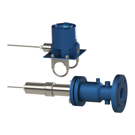
2. INSTALLATION Figure 2 shows a typical installation. The HIR features a unique Steam Jacketed Lens Assembly that is mounted directly to the isolation valve, which is mounted on the vessel nozzle flange. The Steam Jacketed Lens Assembly is normally furnished in either a 2 inch or 3 inch flanged process connection size. Ensure the size and type flange on the nozzle isolation valve matches the Steam Jacketed Lens Assembly mounting flange received. -
Page 5: Lens Purge
10 SCFH to 90 SCFH air (0.5 L/min to 41.7 L/min). Connect the purge gas supply to the 1/8” NPT fitting on the top of the Steam Jacketed Assembly. Regulate the purge supply to 15 psig (1 bar). Delta Controls recommends using Model HFI Flush Gas Figure 3... -
Page 6: Remote Sensor Mounting - Option Rs
Figure 6 Typical Installation of Remote Fiber Optic Adapter The loop wiring conduit connection on Model HIR is ¾” NPT. Unless the ‘RS’ (remote sensor) option is specified, the fiber optic adapter is normally factory installed in the ½” NPT opening in the housing. -
Page 7: Flameproof Installation
2.3.2 Flameproof Installation When type ‘d’ flameproof protection is employed, wire the HIR as shown in Figure 7 or Figure 8. Use certified cable glands and conduit seals for all flameproof installations. Figure 7 Typical Wiring Note: F-range shown; other ranges use a two-wire fiber optic adapter Figure 8 Typical Wiring - Option RS (Remote Sensor) Note: F-range shown;... -
Page 8: Connecting The Fiber Optic Cable
1. Insert the cable into the fiber optic adapter. The cable must be inserted all the way to the bottom of the adapter hole for the cable grip to seat and to avoid calibration errors. 2. Tighten the cable grip to seal the cable against moisture. Model HIR Electronics Housing ¾” NPT... -
Page 9: Optical Alignment
2.5 Optical Alignment The fiber optic lens is aligned at the factory to look straight down the nozzle’s bore. The alignment should be visually checked prior to using the instrument. This alignment check is only possible when there is light inside the reactor vessel, either with the vessel opened and lighted prior to operation, or from the light from the reaction after startup. -
Page 10: Operation
Model HIR user interface consists of an LCD display and 4 setup pushbuttons. The temperature characteristics of the display are such that you should only calibrate the unit when the ambient temperature is between 0 F and +140 F (-18 C through +60 C). -
Page 11: Initial Startup
The parameters listed below are normally used only during factory setup. However, they can be accessed by pressing and holding the NEXT button while simultaneously pressing the UP arrow button. CAUTION: Accessing these parameters can result in at least momentary disruption of the transmitted 4-20 mA signal as described below under Zero Adj and Span Adj. -
Page 12: Two Color Sensing
In that case, the amount of blockage cannot be determined. 3.4 Preventive Maintenance Model HIR is designed to give years of trouble-free operation without the need for service. In most cases, to achieve this performance, the only requirement is that the optical path (nozzle, valve, window) temperature be maintained above the freezing point of sulfur, and that the window purge be maintained to keep the window free of particulates. -
Page 13: Calibration
1. Measure reactor temperature using a CLAUSTEMP model HIP handheld pyrometer or other means. ® 2. Ensure Model HIR has a clear sight path into the reactor. 3. Press and hold the NEXT button while simultaneously pressing the UP arrow button. Then release both buttons. - Page 14 Figure 13 - Dimensions – Electronics Housing 14 of 15...
-
Page 15: Specifications
4. SPECIFICATIONS Range: “C” Range +1472 °F to +3092 °F (+800 °C to +1700 °C) “D” Range +662 °F to +3092 °F (+350 °C to +1700 °C) “F” Range Dual Wavelength +1472 °F to +3092 °F (+800 °C to +1700 °C) Single Wavelength +662 °F to +3092 °F (+350 °C to +1700 °C) Accuracy...
Need help?
Do you have a question about the HIR and is the answer not in the manual?
Questions and answers