Advertisement
Quick Links
P E N G U I N
P E N G U I N
I n s t a l l a t i o n
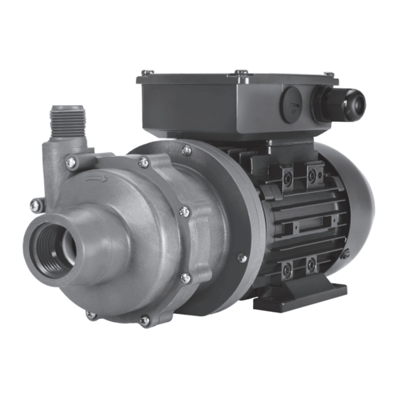
Magnetic Drive Pump
Series MTD
MODELS
MTD-1/8
MTD-1/4
MATERIALS
B - Polypropylene
C - PVDF (Kynar)
INTRODUCTION
Penguin magnetic-driven pumps are designed to handle a large range of chemicals without diffi culty. Constructed of polypropylene, kynar,
Series M pumps have an upper working temperature of 190/220/250 degrees, respectively, and thus can handle highly corrosive or mild
chemicals, acids or solvents. Series M pumps eliminate the conventional shaft seal found in most pumps. This means that there is no rotating
seal to wear out and allow the liquid being pumped to leak out. The pumping action may eventually fail, however, the liquid can never leak
out. Series M pumps are easy to install and operate, and are virtually maintenance free. All pumps have been tested for proper operation
before leaving the factory. To obtain optimum service life, please follow all instructions.
RECOMMENDATIONS
Install the pump as close as possible to the liquid reservoir from which the liquid is being pumped. As more energy is necessary to prime the liquid than to
discharge the fl uid, make the suction as short as possible.
Always make sure there is enough liquid in the reservoir and the level is high enough considering the capacity of the pump unit. Inadequate liquid will cause
vortex in the reservoir. A vortex occurs when air mixes from the surface into the fl uid. This can disturb the fl ow and also prevents the pump from priming.
Never run the pump for more than 5-10 minutes against a closed discharge valve. This will cause overheating of the fl uid in the pump and will damage the
polypropylene parts. Temperature in this case will increase up to 220 degrees. If the pump is being run against a closed discharge valve for a long duration
of time, install a small bleed line back into the reservoir before the discharge valve of the pump. If the line is small, there is a minimum pressure loss. This
prevents overheating by recirculating the fl uid.
ELECTRICAL
Model MTD-1/14 and M-1/8 pumps are supplied as standard in a single phase, single voltage, 115V, 50/60c motor with 230V as an option. All other models
supplied with a single phase are dual voltage, 115/230V motors. The factory wires all dual voltage motors for the lower voltage (115V) unless otherwise
requested. When changing from 115V wiring to 230V wiring, follow the motor manufacturer's wiring instructions, which are found in the motor junction box or
motor label. Be sure to wire the motor for clockwise rotation as viewed from the suction entrance of the pump. A power cord and plug are supplied for immediate
plug-in operation on motors wired for the lower voltage. These motors have already been wired at the factory for proper rotation. A plug is not supplied on
motors wired 230V. Motors supplied in three-phase are dual voltage, 230/460V, 50/60c which are not wired at the factory. Since direction of rotation cannot
be determined without operating the pump, the motor rotation must be checked before operation. Attach leads to motor and bump start. Since these pumps
must not run dry for more than 10 seconds, do not leave motor running. As viewed from the suction entrance of the pump, check for clockwise rotation. If
counterclockwise rotation, change any two leads and check rotation again. Many options are available on the M Series motors including explosion-proof and
special voltage motors. If any of these options are required, please check the motors carefully or consult factory.
PLUMBING
It is recommended to enlarge the suction line a minimum of one size larger than the suction entrance. Never reduce plumbing on the suction. Avoid 90 degree
elbows and never use a 180 degree elbow. Make sure that every suction coupling/connection is airtight. Always use a valve on the discharge of the pump.
In case of a fl ooded suction, in which the liquid level is higher than the center of the suction entrance, provide a T-connection with a small valve after the
discharge valve to assist in letting the air out during fl ooding. In case of a non-fl ooded suction, in which the liquid level is lower than the center of the suction
entrance, provide a foot valve on the end of the submerged suction line.
&
M a i n t e n a n c e
Advertisement

Subscribe to Our Youtube Channel
Related Manuals for Penguin MTD-1/8


Summary of Contents for Penguin MTD-1/8
- Page 1 INTRODUCTION Penguin magnetic-driven pumps are designed to handle a large range of chemicals without diffi culty. Constructed of polypropylene, kynar, Series M pumps have an upper working temperature of 190/220/250 degrees, respectively, and thus can handle highly corrosive or mild chemicals, acids or solvents.
-
Page 2: Model Number And Serial Number
IMPORTANT INFORMATION - READ FIRST Model Number and Serial Number Record the model number and serial number below for future reference. This is important information when ordering replacement parts or when technical assistance is required. The numbers are found on a label located on the motor adapter. Model Number___________________________ Serial Number___________________________ Chemical Reaction Disclaimer... - Page 3 Polypropylene: 180º F (82º C); PVDF: 220º F (104º C) NOTE: Maximum temperature is application dependent. Consult a chemical resistance guide or the chemical manufacturer for chemical compatibility and temperature limits. Solids: Maximum particle size is 100 microns for slurries and 1/64” (.4 mm) for infrequent particles. Maximum hardness is 80 HS. Maximum concentration is 10% by weight. Pumping solids may lead to increased wear. Minimum Allowable Flow Rate: Do not allow the fl ow rate to drop below the minimum fl ow rate listed in the chart below. 3450 rpm 2900 rpm .25 gpm .95 lpm (.95 lpm) (.25 gpm) Maximum Allowable Motor Power: Do not exceed the maximum power rating for the pump coupling. Standard coupling for the MTD-1/8, MTD-1/4 is 6 pole. Maximum motor power is 1/4 horsepower (.18 kW). Standard coupling for the DB5.5 is 8 pole. Maximum motor power is 1/2 horsepower (.37 kW). Maximum Noise Level: 60 dBA (pump only) Unpacking and Inspection Unpack the pump and examine for any signs of shipping damage. If damage is detected, save the packaging and notify the car- rier immediately.
- Page 4 Assembly...
- Page 5 Assembly...
- Page 6 Motor/Electrical/Maintenance/Disassembly Motor/Electrical 3. Close the discharge valve. 4. Turn the pump on. Slowly open the discharge valve. Adjust the fl ow rate and pressure by regulating the discharge valve. Do not Motor/Electrical attempt to adjust the fl ow with the suction valve. Only qualifi ed personnel trained in the safe installation and opera- 5. Use of a power monitor is strongly recommended for pumps tion of this equipment should install the motor. Install the motor with PTFE bushings. The power monitor will stop the pump and according to National Electric Code, NEMA MG-2, IEC standards help prevent damage if the pump should run dry. requirements and/or applicable local electrical codes. The voltage and frequency variations of the power supply should never Shutdown exceed the limits established in the applicable standard. Prior to connect-ing to the power line, check nameplate voltage, rotation Use the following procedure to shutdown the pump. connection and ensure proper grounding. Suffi cient ventilation area should be provided to insure proper operation and cooling 1. Slowly close the discharge valve.
- Page 7 Disassembly/Reassembly...
- Page 8 Disassembly/Reassembly...
-
Page 9: Troubleshooting
Troubleshooting Section VII - Troubleshooting General Notes: • Do not pump liquids containing ferrous metal fines. • If magnets decouple, stop pump immediately. Operating the pump with the magnets decoupled will eventually weaken the magnets. • Do not use mismatched drive magnet assemblies (different number of magnets on inner and outer drive magnet as semblies). • Phone FTI’s Technical Service Department, 1-800-888-3743, or e-mail, techservice@finishthompson.com, if you have any questions regarding product operation or repair. No or Insufficient Discharge • Air leaks in suction piping • Pump not primed • System head higher than anticipated • Closed valve • Viscosity or specific gravity too high • Motor too large for magnet coupling rating (magnets uncoupled) • Suction lift too high or insufficient NPSH • Clogged suction line or impeller vanes • Motor rotation incorrect (correct rotation when viewed from the fan end is counter clockwise) - Page 10 MTD-1/8 & MTD-1/4 Spare Parts MTD-1/8, MTD-1/4 SPARE PARTS LIST & PRICES MTD-1/8, 1/8 HP, 56 B-14 FRAME MTD-1/4, 1/4 HP, 63 B-14 FRAME ITEM POLYPRO PVDF POLYPRO PVDF QTY. DESCRIPTION Impeller housing w/thrust ring & housing screws, NPT MTD-A102865-1 MTD-A102865-3 MTD-A102865-1 MTD-A102865-3 Housing o’ring, Viton MTD-J03572 Housing o’ring, EPR MTD-103571 Impeller ass’y w/thrust ring & carbon bushing, 6-pole magnets MTD-110410-5 MTD-110410-6 MTD-110410-1 MTD-110410-2 Impeller ass’y w/thrust ring & PTFE bushiing, 6-pole magnets MTD-110410-11 MTD-110410-12 MTD-110410-7 MTD-110410-8 Impeller thrust ring, PTFE MTD-102141 Impeller bushing, carbon MTD-J102387 Impeller bushing, PTFE MTD-J102790 Motor adaptor/barrier w ceramic shaft & silicon carbide thrust washer...
Need help?
Do you have a question about the MTD-1/8 and is the answer not in the manual?
Questions and answers