Table of Contents
Advertisement
Quick Links
K E E S T A R S E W
INSTRUCTIONS AND ILLUSTRATED PARTS MANUAL
BETRIEBSANLEITUNG UND ILLUSTRIERTES TEILEVERZEICHNIS
FOR STYLES / FÜR TYPEN
81300A, AJ, A1H, A2
81300B, B1H, B2
INSTRUCTIONS AND ILLUSTRATED PARTS LIST FOR
PREFACE
81300 SERIES MACHINES
This catalog has been prepared to guide you while operating 81300
series machines and arranged to simplify ordering spare parts.
First Edition
Advertisement
Table of Contents

Related Manuals for Keestar 81300 Series


Summary of Contents for Keestar 81300 Series
- Page 1 FOR STYLES / FÜR TYPEN 81300A, AJ, A1H, A2 81300B, B1H, B2 INSTRUCTIONS AND ILLUSTRATED PARTS LIST FOR PREFACE 81300 SERIES MACHINES This catalog has been prepared to guide you while operating 81300 series machines and arranged to simplify ordering spare parts. First Edition...
- Page 2 Sicherheitshinweisen für den Betrieb und das Einstellen dieser maintain the superior performance and reliability designed Maschinen hält die hohe Leistung und Betriebssicherheit and built into every KEESTAR SEW bag sewing machine. dieser KEESTAR SEW Sacknähmaschinen aufrecht. Adjustments and cautions are presented in sequence so that Einstellungen und Sicherheitshinweise sind folgerichtig im a logical progression is accomplished.
- Page 3 BENÜTZUNG DIESER BETRIEBSANLEITUNG ORDERING WEAR AND SPARE PARTS BESTELLEN VON VERSCHLEISS- UND ERSATZTEILEN STYLES OF MACHINES MASCHINENTYPEN INSTALLATION 8 - 9 AUFSTELLUNG LUBRICATING 10 - 11 ÖLEN NEEDLES NADELN THREADING DIAGRAM EINFÄDELANLEITUNG OPERATING INSTRUCTIONS BEDIENUNGSANLEITUNG MAINTENANCE WARTUNG INSTRUCTIONS FOR MECHANICS 14-22 MECHANIKERANLEITUNG VIEWS AND DESCRIPTION OF PARTS...
- Page 4 ELEKTROPNEUMATIK-TEILESATZ FÜR OBERTRANSPORTDRUCK UND -LIFTUNG FÜR 81300A1H, A2, B1H, B2 CONTROL FOR ELECTRO-PNEUMATIC HOT THREAD CHAIN CUTTER FOR 81300A1H, B1H 42 - 45 STEUERUNG FÜR ELEKTROPNEUMATISCH BETÄTIGTEN FADENKETTEN-HEISSSCHNEIDER FÜR 81300A1H, B1H ELECTRO-PNEUMATIC HOT THREAD CHAIN CUTTER FOR 81300A1H, B1H 46 - 47 ELEKTROPNEUMATISCH BETÄTIGTER FADENKETTEN-HEISSSCHNEIDER FÜR 81300A1H, B1H SEWING PARTS 48 - 49...
- Page 5 Only genuine spare parts approved by KEESTAR SEW have to be used for repairs. These parts are designed specifically for your machine and manufactured with utmost precision to assure long lasting service.
- Page 6 IDENTIFICATION OF MACHINES Bedienungsperson aus, wenn nicht anders angegeben. Handrad- Each KEESTAR SEW 81300 series machine is identified by a style number, Riemenscheibe dreht sich which is stamped on the style plate affixed to the right front of machine. Uhrzeigersinn in Nährichtung, vom Serial number is stamped into bed casting at the right front base of rechten Ende der Maschine aus gesehen.
-
Page 7: Styles Of Machines
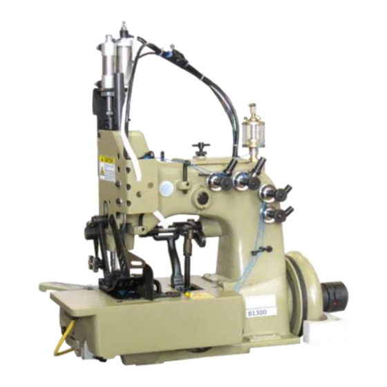
STYLES OF MACHINES MASCHINENTYPEN 81300A: Combined ANTAEUS / HERAKLES two needle four thread 81300A: Kombinierte ANTAEUS / HERAKLES Zweinadel-Vierfaden- safety stitch machine. Lower and upper feed. Adjusted for Sicherheitsnahtmaschine. Unter- und Obertransport. Justiert für polypropylene sewing threads. Polypropylen-Nähfäden Manuelle Schmierung. Manual lubrication. - Page 10 CAUTION! In case the direction of rotation has to be INSTALLATION (continued) Unpack the sewing machine and the accessories. changed, the reversing of the polarity is only Mount the base plate (A) with four screws, nuts and allowed to be done by a skilled electrician. washers (B) in the provided holes on the table board.
- Page 11 prüfen Sie die Drehrichtung. Lassen Sie das Pedal sofort wieder LUBRICATING ÖLEN los. Schalten Sie aus und warten Sie den Stillstand des Motors CAUTION! Turn off main power switch before lubricating! ACHTUNG! When using clutch motors with or without actuation ACHTUNG! Wenn die Drehrichtung geändert werden muß, darf das lock wait until motor has completely stopped.
-
Page 12: Threading Diagram
Zum Ölen empfehlen wir "Mobil Oil DTE Medium" oder ein gleichwertiges Öl, das von KEESTAR SEW in 1/2 Liter Behältern unter For lubrication we recommend "Mobil Oil DTE Medium" or der Teilnummer G28604L oder in 5 Liter Behältern unter der equivalent, which can be purchased from KEESTAR SEW in Teilnummer G28604L5 bezogen werden kann. - Page 13 EINFÄDELANLEITUNG ACHTUNG! Schalten Sie vor dem Einfädeln den Hauptschalter aus! Warten Kupplungsmotoren oder ohne Betätigungssperre den Stillstand des Motors ab! Fig. 2...
-
Page 14: Wartung
BEDIENUNGSANLEITUNG THREADING EINFÄDELN 81300 series are threaded as shown in Fig. 2. Die Maschinen 81300 werden, wie in Fig. 2 gezeigt, eingefädelt. Drehen Sie zum Einfädeln der Nadel das Handrad in Nährichtung bis For threading the needle turn handwheel in operating die Nadel in ihrer obersten Stellung ist. - Page 15 The left needle forms along with the left lower looper at the front the needle bar when making this adjustment. Retighten clamp and the upper cross looper the double locked stitch type 401 screw. (ANTAEUS). INSERTING THE NEEDLES MECHANIKERANLEITUNG Before adjusting the machine insert HINWEIS: Die rechte Nadel bildet zusammen mit a new set of needles with the shank dem Untergreifer links hinten, dem rechten...
- Page 16 rechten Nadel steht. In dieser Stellung müssen Unterkante Greifer und Oberkante Nadelöhr bündig sein. Ist eine Einstellung notwendig, lösen Sie die Klemmschraube (A, Fig. 4) im Nadelstangenmitnehmer und schieben Sie die Nadelstange (B) entsprechend nach oben oder unten. Beachten Sie, daß bei dieser Einstellung die Ausrichtung der Nadelstange nicht verändert wird.
- Page 17 SETTING THE RIGHT UPPER SPREADER FOR THE OVEREDGE EINSTELLUNG DES RECHTEN OBEREN BLINDGREIFERS FÜR DEN STITCH ÜBERWENDLICHSTICH Before inserting a new spreader (F, Fig. 6) remove thread hook Bevor Sie einen neuen Blindgreifer (F, Fig. 6) einsetzen, entfernen Sie (J). This facilitates the visual check of the adjustment. den Fadenhaken (J).
- Page 18 SETTING THE THREAD RETAINER FOR THE OVEREDGE STITCH Viewed from the left end of the machine the thread retainer (B, Fig. 11) SETTING THE RIGHT UPPER SPREADER FOR THE OVEREDGE should pass as close as possible on the left side of lower looper (A) when STITCH (continued) swinging upward without contacting it.
- Page 19 SETTING THE CROSS LOOPER FOR DOUBLE LOCKED STITCH The distance (set at the factory) from center to center of the two ball joints driving the cross looper should be 51 mm (2") (see Fig. 13). Basically the front ball joint (H, Fig. 13) should be positioned as far as it will go to the left in the fastening slot of the cross looper drive lever (J).
-
Page 20: Setting The Needle Guard
Standardmäßig soll das vordere Kugelgelenk (H, Fig. 13) so weit SETTING THE NEEDLE GUARD wie möglich nach links im Befestigungslangloch des When the needle guard (A, Fig. 16) is in its most forward end position, Quergreifer-Antriebhebels (J) gestellt werden. its guarding surfaces should just contact the back of the needles without Beim Drehen Handrades... - Page 21 THROAT PLATE SUPPORT Assemble the throat plate support (A, Fig. 20) with screws (B) so that it does not interfere with the feed dog or any other machine parts. EINSTELLUNG DES NADELANSCHLAGS Wenn der Nadelanschlag (A, Fig. 16) in seiner vorderen Endstellung ist, sollen seine Schutzflächen die Rückseite der SETTING THE UPPER FEED DOG Nadeln gerade berühren, ohne sie abzulenken.
- Page 22 Simultaneously the upper feed dog (B, Fig. 19) should be EINSTELLUNG DES OBEREN TRANSPORTEURS positioned so that the tips of its teeth Montieren Sie den Obertransporteur (B, Fig. engage with the tooth spaces of the 21) und den lower feed dog (A), without contacting Drückerfuß...
- Page 23 Zum Einstellen lösen Sie die beiden Schrauben (H, Fig. 22) und stellen das Stützlager (J) höher, wenn der Obertransporteur mehr oder tiefer, wenn er weniger abheben soll. Ziehen Sie die Schrauben (H) wieder an. PRESSER FOOT PRESSURE ON 81300A, AJ, B Rotate handwheel until the lower feed dog is below the throat plate.
- Page 24 EDGE GUIDE AND STITCH TONGUE Nun drehen Sie die Knebelschraube (B, Fig. 24) soweit ein, daß der zum einwandfreien Transport notwendige Drückerfußdruck erzeugt wird Set the edge guide (A, Fig. 26) laterally as close as possible to (durch Nähversuche ermitteln). Sichern Sie diese Einstellung mit der the presser foot without contacting it.
-
Page 25: Views And Description Of Parts
The tension applied on the needle threads should be fairly Soll mehr Nadelfaden abgezogen werden (abhängig von Faden und strong to produce uniform stitches. Nähgut), stellen Sie die Set the collar for the needle thread tension on the up and down Nadelfadenabzugs-Rollenführung entsprechend höher. - Page 26 BUSHING, SIGHT FEED OILER, SPRING VALVE OILER...
- Page 27 BUCHSEN, TROPFÖLER, KUGELÖLER Ref. No. Part No. Description Beschreibung Amt. Req. Pos. Nr. Teil Nr. Anzahl 80862 Presser Bar Bushing Buchse für Drückerfußstange 2* 81373A Needle Bar Bushing Buchse für Nadelstange 2 3 GR-80293A Oil Distributor Ölverteiler 1 22894K Spot Screw, headless Gewindestift mit Spitze 22894J Set Screw Gewindestift 666-79...
- Page 28 29916RER Bushings for looper drive rocker shaft Buchsen für Greiferantriebs-Schwingwelle (Ref. No. 18) (Pos. Nr. 18) 29916REP Bushings for crankshaft (Ref. No. 26) Buchsen für Kurbelwelle (Pos. Nr. 26) 29916REH Bushings for cross looper drive shaft Buchsen für Quergreifer-Antriebswelle (Ref. No. 40) (Pos.
- Page 30 Ref. No. Part No. Description Beschreibung Amt. Req. Pos. Nr. Teil Nr. Anzahl 80673CB Needle Bar Guard Nadelstangenschutz 80888 Arm Cover Armdeckel 1 80764 T-Screw Knebelschraube 1 35733B Knurled Nut Rändelmutter 81387 Face Cover Stirndeckel 1 22528 Screw Schraube 2 A9453A Finger Guard Fingerschutz...
- Page 32 Description Beschreibung Anzahl HS106 Tension Post Spannungsbolzen 81292A Tension Post Spannungsbolzen 1 99623A Spacer Distanzbuchse 80669B Tension Post Ferrule Hülse für Spannungsbolzen 80676A Tension Disc Spannungsscheibe 8 HA1349 Tension Sleeve Federhülse 4 HS110A Spring for needle thread tension Feder für Nadelfadenspannung 2 110-2 Spring for looper thread tension Feder für Greiferfadenspannung 2 107 Tension Spring Ferrule...
-
Page 33: Thread Tensions And Thread Guide Parts Fadenspannungen Und Fadenführungsteile
Ref. No. Part No. Amt. Req. Pos. Nr. Teil Nr. 22743 Set Screw Gewindestift 1 81365A Needle Thread Take-up Roller Nadelfadenabzugs-Rollenführung, komplett 1 Guide Assembly 81365 Roller Support Rollenhalter 1 81386 Roller Stud Assembly Rollenbolzen, komplett 22560 Set Screw Gewindestift 1 HA1286B Spring Feder 1 12964C Spring Ball Federkugel 1... - Page 35 Ref. No. Part No. Amt. Req. Pos. Nr. Teil Nr. NEEDLE BAR, NEEDLE LEVER, CRANK SHAFT, HANDWHEEL NADELSTANGE, NADELHEBEL, KURBELWELLE, HANDRAD Description Beschreibung Anzahl 81317 Needle Bar Nadelstange 80620H Sleeve Spannhülse 81356B Needle Stop Plate Nadelanschlagplättchen 1 Countersunk Screw Senkschraube 81356A Needle Holder Nadelhalter 1 Set Screw for left needle Gewindestift für linke Nadel...
- Page 36 22587 Screw Schraube 80656 Ball Stud Kugelbolzen 1 80636A Guide Fork Führungsgabel G22515A Screw Schraube 80630C Nut, left hand thread Mutter, Linksgewinde 80630 Needle Lever Connection Rod Nadelhebel-Verbindungsstange 1 80630G Oil Felt Ölfilz 1 80630D Nut, right hand thread Mutter, Rechtsgewinde PI18 Pin for oil felt Stift für Ölfilz...
- Page 37 Ref. No. Part No. Amt. Req. Pos. Nr. Teil Nr.
- Page 38 Description Beschreibung Anzahl 81364 Drive Fork for cross looper Antriebsgabel für Quergreifer Screw Schraube 81364A Guide Plate Führungsplättchen 2 Screw Schraube 81370 Oil Felt Ölfilz 1 81366 Drive Eccentric for cross looper Antriebsexzenter für Quergreifer Spot Screw, headless Gewindestift mit Spitze Set Screw Gewindestift 1 81363A...
- Page 39 Ref. No. Part No. Amt. Req. Pos. Nr. Teil Nr. Set Screw Gewindestift 2 99240 Screw Schraube Mutter 81339 Drive Lever for upper spreader Antriebshebel für oberen Blindgreifer 1 BP108 Hex. Head Cap Screw Sechskantschraube 1 81358 Ball Joint Assembly Kugelgelenk, komplett 81358B Ball Stud Kugelschraube...
- Page 41 LOOPER DRIVE MECHANISM GREIFERANTRIEBSMECHANISMUS Ref. No. Part No. Description Beschreibung Amt. Req. Pos. Nr. Teil Nr. Anzahl 1 - 70 See preceding page Siehe vorhergehende Seite Nut Mutter 35741A Connecting Rod Verbindungsstange Nut, left hand thread Mutter, Linksgewinde 1 81357 Ball Joint Assembly Kugelgelenk, komplett 1 81345 Ball Stud Kugelschraube...
-
Page 42: Lower And Upper Feed Drive Mechanism
LOWER AND UPPER FEED DRIVE MECHANISM... - Page 43 UNTER- UND OBERTRANSPORT-ANTRIEBSMECHANISMUS Ref. No. Part No. Description Beschreibung Amt. Req. Pos. Nr. Teil Nr. Anzahl 80740 Drive Shaft Antriebswelle 80791 Drive Lever Antriebshebel BP108 Hex. Head Cap Screw Sechskantschraube 1 51147 Collar Stellring Set Screw Gewindestift 2 80790 Rocker Lever Kulissenhebel BP108 Hex.
- Page 44 Washer Scheibe HA43X Feed Lift Eccentric Transporthubexzenter 22894D Spot Screw, headless Gewindestift mit Spitze G29099R Feed Drive Eccentric Assembly Transportantriebsexzenter, komplett 1 81351 Connecting Link Verbindungsgelenk 1 22587 Screw Schraube 666-121 Oil Wick Öldocht 666-19 Oil Wick Öldocht 80654 Bushing Buchse 81395 Eccentric Exzenter...
- Page 45 Ref. No. Part No. Description Beschreibung Amt. Req. Pos. Nr. Teil Nr. Anzahl...
- Page 46 80648 Lifter Lever Lifterhebel 1 420 Shoulder Screw for lifter lever Ansatzschraube für Lifterhebel 80649 Spring Feder 1 80631 Guide Plate Führungsplättchen Screw Schraube 4 81566A Collar Stellring 99376A Screw Schraube 1 80666D Collar Stellring 22894C Set Screw Gewindestift 80663 Leaf Spring, upper Blattfeder, oben 3 80664...
- Page 48 ELECTRO-PNEUMATIC PARTS KIT FOR UPPER FEED PRESSURE AND LIFTER FOR 81300A1H, A2, B1H, B2 WITH ELECTRONIC DRIVE ELEKTROPNEUMATIK-TEILESATZ FÜR OBERTRANSPORTDRUCK UND -LIFTUNG FÜR 81300A1H, A2, B1H, B2 MIT ELEKTRONIK-ANTRIEB Ref. No. Part No. Pos. Nr. Teil Nr. 999-210A 1-33,35 A10455-813E 99683C 1-22, A10455H813E...
- Page 49 Description Beschreibung Amt. Req. 997A852, not shown Anzahl Presser Bar, left for Electro-Pneumatic Parts Kit for upper feed Elektropneumatik-Teilesatz für 81300A1H, pressure and lifter for 81300A2, Obertransportdruck und -liftung für A2, B1H, B2, see page 81300A2, B2 Electro-Pneumatic Parts Kit for upper feed Elektropneumatik-Teilesatz für Obertransportdruck, -liftung und Fadenketten-...
- Page 51 Ref. No. Pos. CONTROL FOR ELECTRO-PNEUMATIC HOT THREAD CHAIN CUTTER FOR 81300A1H, B1H STEUERUNG FÜR ELEKTROPNEUMATISCH BETÄTIGTEN FADENKETTEN-HEISSSCHNEIDER FÜR 81300A1H, B1H Part No. Description Beschreibung Amt. Req. Teil Nr. Anzahl 99712HAE Control for Hot Thread Chain Cutter Steuerung für Fadenketten-Heißschneider 134001 PA Tube 6 x 4;...
- Page 53 Ref. No. Pos. CONTROL FOR ELECTRO-PNEUMATIC HOT THREAD CHAIN CUTTER 81300A1H, B1H STEUERUNG FÜR ELEKTROPNEUMATISCH BETÄTIGTEN FADENKETTEN-HEISSSCHNEIDER 81300A1H, B1H Part No. Description Beschreibung Amt. Req. Teil Nr. Anzahl Control Box of hot thread chain Steuergerät des Heißschneiders für cutter 999-315B Control Fadenkette 999-315B 90242TA Board...
- Page 55 Ref. No. Part No. Pos. Nr Teil ELECTRO-PNEUMATIC HOT THREAD CHAIN CUTTER FOR 81300A1H, B1H ELEKTROPNEUMATISCH BETÄTIGTER FADENKETTEN-HEISSSCHNEIDER FÜR 81300A1H, B1H Description Beschreibung Amt. Req. Anzahl 99712H813 999- El.-Pneum.Hot Thread Chain Cutter Hot El.-pneum.Fadenketten-Heißschneider 315B Cutter for thread chain with control box Heißschneider für Fadenketten mit Knife for hot cutter, w-shape Steuergerät...
- Page 57 Part No. Teil Nr Ref. No. NÄHTEILE Beschreibung Amt. Req. Pos. Nr. Anzahl Transporteur, oben 81326 Description Schraube 136A Drückerfuß, komplett 81320C Feed Dog, upper Drückerfußsohle Schraube 81330C Screw Drückerfußzunge, gezeichnet "WL" 22596B Presser Foot Assembly Schraube 81597A-10 Presser Foot Bottom Screw Stichplatte für 81300AJ 22596B Presser Foot Tongue, marked "WL"...
- Page 58 *ÄHNLICHE TEILE, JEDOCH MIT ANDEREM GEWINDE; BITTE MESSEN SIE DEN DURCHMESSER DES STEHBOLZENS HA18A Nut, Q2 thread Mutter, Q2 Gewinde Washer Scheibe 99241 Stud, Q2 thread, Ø 5.44 mm Stehbolzen, Q2 Gewinde, Ø 5,44 mm G5144 Nut, J2 thread Stehbolzen, J2 Gewinde Washer Scheibe 80686C...
- Page 59 Part No. Teil Nr...
-
Page 60: Important Hint
ACCESSORIES ZUBEHÖR Ref. No. Description Beschreibung Amt. Req. Pos. Nr. Anzahl G21139 Thread Stand Assembly Fadenständer, komplett G21139A Spool Seat Fadenteller 1 G22632F24 Square-head Bolt Vierkantschraube 22509 Square-head Bold Vierkantschraube 21104B11 Rod Stange HA69B Thread Rod Fadenstange 96658 Roll Pin Spannhülse G69R Thread Rod Extension Fadenstangen-Verlängerung 1... - Page 61 Part No. Teil Nr...
- Page 62 Ref. No. Part No. Description Beschreibung Amt. Req. Pos. Nr. Teil Nr. Anzahl 93065D2 Thread Stand, 2 Cones Fadenständer, 2-teilig 1 93065D3 Thread Stand, 3 Cones Fadenständer, 3-teilig 93065D4 Thread Stand, 4 Cones Fadenständer, 4-teilig 93065D5 Thread Stand, 5 Cones Fadenständer, 5-teilig 93065DA Thread Stand Base...
-
Page 63: Accessories Zubehör
90233EB Wire for potential equalization Potentialausgleichsleiter 1 48 95182V Ground Screw Erdungssschraube 1 ACCESSORIES ZUBEHÖR... - Page 64 NUMERICAL INDEX OF PARTS NUMERISCHES TEILEVERZEICHNIS Part No. Page Part No. Page Part No. Page Part No. Page Teil Nr. Seite Teil Nr. Seite Teil Nr. Seite Teil Nr. Seite 1021U ... 53 22894H ... 31 80630 ... 31 81086C ... 29 10455E ...
- Page 65 2145 ... 37 51147 ... 37 80691 ... 33 81317 ... 31 21608 ... 29 51487 ... 49 80692EA ... 25 81320C ... 49 2165C1.0 ... 47 51847 ... 37 80694DA ... 25 81321B ... 31 2166A ... 47 6040A ... 33 80696 ...
- Page 66 Part No. Page 93065DG ... 53 99681J ... 51, 53 A10278A10 ... 49 93065DH ... 53 99681JA ... 51, 53 A10278B5 ... 49 Teil Nr. Seite 93065DJ ... 53 99683C ... 41 99683M ... 41 A10278B6 ... 49 93065DT ... 53 99711LH ...
- Page 67 HA20A ... 37 HA81 ... 25 M129K ... 25 TR54 ... 25 HA20B ... 41 HA95 ... 25 M129KR ... 25 TT16 ... 53 HA23 ... 37 HS106 ... 29 HA43X ... 37 HS110A ... 29 PI18 ... 31, 33, 37 WR56 ...
- Page 68 KEESTAR Keestar Sewing Machine Co. Add: No.3 Gongnonglu Road, Xi'an 710014, Shaanxi, P.R.China Tel:0086-29-84273415 Fax:0086-29-63364003 www.keestarsewing.com...
Need help?
Do you have a question about the 81300 Series and is the answer not in the manual?
Questions and answers