
Related Manuals for Gree GMV-VDR5PH/SA-S


Summary of Contents for Gree GMV-VDR5PH/SA-S
- Page 1 Owner's Manual Original Instructions Commercial Air Conditioners ERV+DX coil Models: GMV-VDR5PH/SA-S GMV-VDR8PH/SA-S GMV-VDR10PH/SA-S...
- Page 2 To Users Thank you for selecting Gree product. Please read this instruction manual carefully before installing and using the product, so as to master and correctly use the product. In order to guide you to correctly install and use our product and...
- Page 3 Exception Clauses Manufacturer will bear no responsibilities when personal injury or property loss is caused by the following reasons: (1) Damage the product due to improper use or misuse of the product. (2) Alter, change, maintain or use the product with other equipment without abiding by the instruction manual of manufacturer.
-
Page 4: Table Of Contents
Contents 1 Safety Notices (Please Be Sure to Abide Them) ············· 1 2 Product Introduction ··················································· 5 2.1 Function Introduction ····················································· 5 2.2 Major Structure ····························································· 7 2.3 Outline Dimensions ······················································· 8 2.4 Performance Parameters ················································ 9 2.5 Parameters of Filter and Heat Exchange Core ··················· 10 2.6 List of Accessories ······················································... -
Page 5: Safety Notices (Please Be Sure To Abide Them)
ERV+DX coil 1 Safety Notices (Please Be Sure to Abide Them) SPECIAL WARNING: (1) Do not pierce or burn. (2) Do not use means to accelerate the defrosting process or to clean, other than those recommended by the manufacturer. (3) Be aware that refrigerants may not contain an odor. PROHIBITED: This sign indicates that the operation must be prohibited. - Page 6 ERV+DX coil The air conditioner must be properly Before installation, grounded through a please check the power receptacle to power cord if it is in avoid electric shock. accordance with the The grounding wire specifications on the shouldn't be nameplate. Make sure connected with a gas the power is safe.
- Page 7 Incorrect work will product directly to cause electric shocks water or place it in a or fire. Please contact damp or corrosive GREE service center environment. for repairs. During cooling mode, Do not turn off the indoor temperature unit until it runs for should not be set too at least 5 minutes.
- Page 8 (such as a bad smell) occurs, stop the unit at once and For safety concern, if disconnect power. the unit is not used for Then contact GREE a long time, please service center. If the remove the power unit continues to plug.
-
Page 9: Product Introduction
ERV+DX coil Please verify For pipe fan and completely before partition wall fan, using the appliance mind the air from the in special places (for open air duct or other example, places appliances that where there are produce open fire precision flowing back into the instruments, food... - Page 10 Free cooling √ Free cooling at night √ The function is available when Centralized control ○ used with Gree centralized controller The function is available when Remote control ○ used with Gree remote monitoring system Remark: √-Standard function, ○-Optional function, ×-Not available.
-
Page 11: Major Structure
ERV+DX coil 2.2 Major Structure Fresh air fan Hook Side access panel component Access panel bolt Air inlet of fresh air Electrical box Air inlet of discharge Air outlet of discharge Side discharge filter Air outlet of fresh air Evaporator Heat exchanger core Natural outlet Water pump... -
Page 12: Outline Dimensions
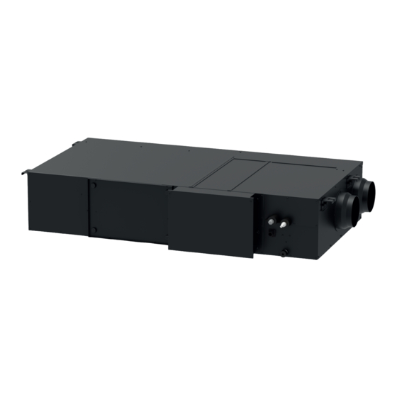
ERV+DX coil 2.3 Outline Dimensions Figure 2-1 GMV-VDR5PH/SA-S Figure 2-2 GMV-VDR10PH/SA-S and GMV-VDR8PH/SA-S Table 2-2 Outline dimensions Measuring unit: mm Model GMV-VDR5PH/SA-S 1700 1762 GMV-VDR8PH/SA-S 1033 1800 1185 1861 GMV-VDR10PH/SA-S... -
Page 13: Performance Parameters
ERV+DX coil Measuring unit: mm Model GMV-VDR5PH/SA-S GMV-VDR8PH/SA-S GMV-VDR10PH/SA-S NOTE! Due to individual differences in production assembly, above figures may vary from those of the present products. Please refer to the actual dimensions of your product. 2.4 Performance Parameters Table 2-3 Performance parameters... -
Page 14: Parameters Of Filter And Heat Exchange Core
ERV+DX coil (2) The nominal static pressure is the static pressure tested acquiescently when leaving the factory, other high-level filter might affect unit performance parameter. (3) Please use Fresh Air Conditioning Load (Cooling) to do capacity calculation or selection. (4) Thermal efficiency is test result that refer to the heating working conditions of the EU1253 instruction. -
Page 15: List Of Accessories
ERV+DX coil NOTE! Conduct cleaning and maintenance periodically for the fresh air side of filter and discharge side of filter. 2.6 List of Accessories Table 2-5 List of accessories Measuring Unit: pc GMV- GMV- GMV- Name Remarks VDR5PH/ SA-S VDR8PH/ SA-S VDR10PH/ SA-S Nut with washer M10×8... -
Page 16: Production Installation
ERV+DX coil 3 Production Installation 3.1 General Specification The user shall entrust professional HVAC engineer to conduct equipment model selection and engineering design, hire experienced construction company to complete the construction. The design and construction shall be consistent with related national stipulations and regulations. This series of unit shall be used with multi VRF unit. - Page 17 Table 3-1 Wiring requirement Wire diameter (mm²) Power Circuit breaker Model specification capacity (A) Ground wire Ground wire GMV-VDR5PH/SA-S 220–240V~ GMV-VDR8PH/SA-S 3x1.0 3x1.0 50/60Hz GMV-VDR10PH/SA-S NOTES! (1) Selection of circuit breaker and power cord in the above table is based upon unit’s maximum power (maximum current).
-
Page 18: Wiring Work
ERV+DX coil e.g. power cable with YJV cross-linked copper, insulated PE and PVC sheath) is lying on the surface of slot (IEC 60364-5-52). If working condition is changed, please adjust the specification according to national standard. (3) Specification of circuit breaker is based on the working condition where ambient temperature of circuit breaker is 40℃. - Page 19 ERV+DX coil single branch line so that the single-core wire can be exposed. 2) Remove the wiring screws on the patch board. 3) Shape the tail of wire into ring by needle nose pliers, and keep the gauge of ring in accordance with screw. 4) Lead the screw across the circle of the single branch line and fix it on the wiring board.
- Page 20 ERV+DX coil Figure 3-1 Diagram for system electric wiring NOTE! Max indoor unit quantity n is according to the outdoor unit capacity. For more details, please refer to the unit capacity configuration. 3.3.3 Selection of Communication Wire (1) Selection of wired controller communication wire Figure 3-2 Diagram of wired controller control connection...
- Page 21 ERV+DX coil Table 3-2 Selection of wired controller communication wire Total length of communication Wire material line between Wire size Material Remarks type indoor unit and standard wired controller L (m) 1) Total length of communication line can't exceed 250m. 2) The cord shall be Light/Ordinary Circular cord (the cores...
- Page 22 ERV+DX coil 3.3.4 Selection of Communication Wire Remark: When installing electrical, you need to replace the rubber ring on the electrical box with the over-the-line rubber ring in the packaged parts. (1) Connection of communication wire between indoor unit and outdoor unit 1) Detach the electric box cover of indoor unit.
- Page 23 ERV+DX coil Figure 3-6 Diagram 2 of wiring board (2) Connection of communication wire of wired controller 1) Detach the electric box cover of indoor unit. 2) The communication between IDU and wired controller shall connect with H1 and H2. 3) One indoor unit can connect two wired controllers (master wired controller and slave wired controller).
-
Page 24: Installation For Pipeline
ERV+DX coil (2) When the indoor unit is controlled by two wired controllers, the addresses of the two wired controllers should be different through address setting. Address 1 is for master wired controller; Address 2 is for slave wired controller. Detailed setting please refer to the owner’s manual of wired controller. - Page 25 ERV+DX coil personal injury. 3) he condensate drainage pipe must be connected to the drainage system specialized for the air conditioner. 4) The shorter the drainage pipe, the better it is. Keep it downward with an inclination of 1°~ 2° or more so that the condensate can be easily drained away.
- Page 26 ERV+DX coil 3) Gasket should be used for the thermal insulation of the pipe clamp and hose. (Thermal insulation should be done after the drainage test.) See the diagram below. Unit: mm 4) If multiple drainage pipes are connected within a system, as show below, please select a drainage header that matches the capacity of the unit.
- Page 27 ERV+DX coil 9) Keep the drain pipe downward with an inclination of 1°~ 2° or more. Therefore, install a supporter every 1000-1500mm. 10) Make sure the weight of drain pipes won’t be borne by the unit. 3.4.3 Drainage Test After completing the installation of the entire drainage pipeline (without insulation cotton), perform a drainage test.
-
Page 28: Engineering Design
ERV+DX coil Figure 3-9 Drainage test 2) Then use a sprayer to spray about 1L of water into the evaporator of the unit through the fresh air opening. Observe from the service panel whether the unit can drain water smoothly. Make sure there is no leakage. (2) Start the water pump of the unit and test if drainage of water pump is smooth. - Page 29 ERV+DX coil Figure 3-10 Maintenance space Table 3-4 Maintenance space Measuring unit: mm Model Pipe gauge GMV-VDR5PH/SA-S 1725 GMV-VDR8PH/SA-S 1620 GMV-VDR10PH/SA-S 1620 NOTE! Some parts of the unit may get loose during transport, so please check the screws of each part of the unit carefully before hoisting the unit, especially the movable parts.
- Page 30 ERV+DX coil 2) When the unit is installed in place, use a level bar to adjust the levelness of the unit. Make sure the unit is horizontal from front to back and has an inclination of 0.5~1° from side to side so that water can be drained through the drainage port.
- Page 31 ERV+DX coil (9) After-sales installers must be equipped with gloves to protect them from sharp objects. 3.5.2 Installation Requirement for Air Ducts This product requires the user to prepare PVC ventilating ducts for outdoor air suction and indoor air discharge. Our unit adopts constant air volume control to ensure constant air volume within a certain range of pipe resistance.
- Page 32 ERV+DX coil (7) If the unit is used in alpine regions or the air outlet is set in a place that faces the wind, please add an air damper to prevent the cold air from entering into the room. (8) Make sure the weight of air ducts will not be borne by the unit. (9) If necessary, use an air hose to connect the air suction duct and air discharge duct during engineering installation.
-
Page 33: Inspection, Pilot Run And Daily Setting
ERV+DX coil Figure 3-13 The flow/pressure diagram NOTE! Before connecting air ducts, please finish the installation of the drainage system and test whether the drainage is normal. 4 Inspection, Pilot Run and Daily Setting 4.1 Check Before Startup After finish installation, please arrange running test to the unit before start operation. -
Page 34: Pilot Run And Debugging Test
ERV+DX coil (7) According to the electric wiring diagram in this manual, check if the power cord complies with related requirements, if the wiring way is correct, if the joint is secured, if the power voltage is normal. 4.2 Pilot Run and Debugging Test Running test: (1) Turn on the unit for running test after connecting power. -
Page 35: Daily Error Inquiry And Maintenance
ERV+DX coil 01:Excellent 02:Good It is used to calculate the time 03:Mild pollution Parameter setting of outdoor for cleaning and replacement 04:Moderate pollution pollution level [default-02] reminder. 05:Severe pollution 06:Serious pollution NOTE! If need to clean or replace the filter at fresh air side or discharge side of filter, the wired controller will display the corresponding cleaning replacement hint in text. -
Page 36: Error Code Table
ERV+DX coil following errors occur, before contacting the after-sales service department of Gree, please conduct troubleshooting on your own according to the following table. Table 5-1 General error diagnosis Abnormality Possible reason Solution Airflow of supply air outlet is Too much dust accumulated... -
Page 37: Maintenance Of Key Components
ERV+DX coil NOTE! Please immediately contact local Gree after-sales company if the above codes are displayed on wired controller, don’t handle it by yourself. 5.3 Maintenance of Key Components Overhaul and replacement of heat exchange core and filter. 1) Unscrew the four bolts of access panel and disassemble the side access panel.
Need help?
Do you have a question about the GMV-VDR5PH/SA-S and is the answer not in the manual?
Questions and answers