
Related Manuals for SIYI FT24


Summary of Contents for SIYI FT24
- Page 1 FT24 User Manual V1.1 FT24 RADIO SYSTEM USER MANUAL V1.1 Jan 2021 2020 SIYI Technology Copyright...
- Page 2 To maintain a safe and orderly public space and to ensure you a good using experience of FT24 Radio System, please read this manual carefully. If you have any issues using the product, please consult the manual or check online pages of FT24 on SIYI official website (http://en.siyi.biz/).
-
Page 3: Table Of Contents
3 GET READY TO USE FT24 ..........................20 3.1 How to Place Transmitter Antenna Right ......................20 3.2 How to Bind FT24 Transmitter with FR / FR Mini Receivers ................. 20 3.3 Throttle Joystick Type ............................22 3.4 Battery / Power Supply ............................. 23 4 MAIN MENUS................................ - Page 4 FT24 User Manual V1.1 5.4 End Point ................................36 5.5 Channel Mapping ............................. 38 5.6 Channel Reverse ............................... 40 5.7 Sub-Trim ................................41 5.8 Trim Setting ..............................42 5.9 Fail Safe ................................44 5.10 ProgMix (Programming and Mixing) ......................45 5.11 Trainer Mode (Master-Slave) .........................
- Page 5 FT24 User Manual V1.1 7.3 Link Status ................................ 81 6.4 Voltage Calibration ............................82 6.5 PWM Settings ..............................84 8 EXPAND SETTINGS ............................. 86 8.1 Bluetooth ................................87 8.2 External (Radio) Module ..........................88 8.2.1 PPM / S.BUS Mode ........................... 88 ....................................
-
Page 6: Read Tips
Mark 1.2 Safety FT24 Radio System is designed for hobbyists, users who approaches to the device should have at least the basic knowledge to operate it. Irregular or irresponsible manipulations to the device may cause damage, property loss, or human injuries. - Page 7 SIYI’s products, please read the prohibited and mandatory terms carefully. Do not use any SIYI radio system to operate your aircraft/vehicle/model at places with intensive crowd (a square, a park), or at places with many obstructions (a street, a parking...
-
Page 8: Batteries
FT24 transmitter is powered by external batteries. Please do read the precautions below before selecting your battery models. The transmitter Micro-USB port does not support charging. Make sure that the battery power, voltage, and volume are compatible with FT24 transmitter’s requirement: 2 x 18650 Li-on Batteries 1 x 2S LiPo Battery (XH 2.54 3-pin Port) -
Page 9: Sd Card
Do not use SIYI radio system when temperature is high, or battery temperature is over 60℃. DANGER Keep SIYI radio system and its parts away from any places that babies or kids may reach easily. The batteries should be taken out of transmitter for careful and safe storage if you are going to stop using the transmitter for more than 3 days. -
Page 10: Storage/Carrying/Recycling
FT24 User Manual V1.1 1.6 Storage/Carrying/Recycling CAUTION Always place your SIYI radio system and its parts at places where babies or kids do not reach. DANGER SIYI radio system should be placed as below: Not too hot (above 60℃) or too cold (under -20℃);... -
Page 11: Introductions
Wireless Communication and Interactivity Farewell to traditional wired communication and interactivity, all made for efficiency and convenience, SIYI‘ s team made their effort to put a great many of 2020 SIYI Tech All Rights Reserved... - Page 12 Data Telemetry of RSSI signal quality, model power battery voltage, and receiver power supply voltage will improve the safety level while users are manipulating their model craft. Besides, FT24 also support data telemetry display and voice 2020 SIYI Tech All Rights Reserved...
- Page 13 RC Relay Two or more remote controllers to relay control one model aircraft for flying over very long distance. Through coordination of two or more users, FT24 breaks the limit distance of single remote control. USB Simulator...
- Page 14 FT24 User Manual V1.1 FT24 remote controller comes with built-in simulator driver. Use a USB cable and connect remote controller to PC, then open the simulator software, users can start flying in the simulator immediately. Diverse Model Settings For Fixed-wings, Helicopters, Gliders, Multi-rotors, Cars, Boats,...
- Page 15 Add a Bluetooth module to the transmitter and connect the receiver to flight controller serial port, FT24 remote control system will be able to receive and analyze flight information telemetry based on Mavlink protocol. Multiple signal output modes: 16CH S.Bus, 8CH PWM.
-
Page 16: Parts
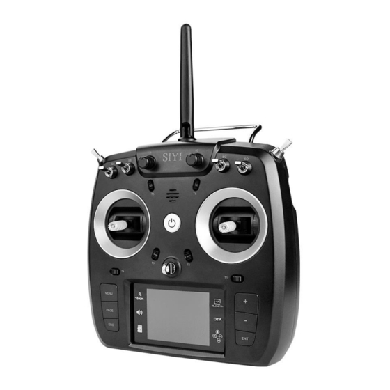
FT24 User Manual V1.1 2.2 Parts 2.2.1 At a Glance Mark: Press and hold the power button three seconds to switch on FT24 transmitter. 2020 SIYI Tech All Rights Reserved... -
Page 17: Interface And Tuner Ports
FT24 User Manual V1.1 2.2.2 Interface and Tuner Ports Bottom Shell Port Function SD Card Slot: Insert your SD card to read and storage files. Micro-USB: Firmware upgrading 2020 SIYI Tech All Rights Reserved... - Page 18 FT24 User Manual V1.1 Back Shell Port Function Audio Port: Trainer and simulator GH1.25MM 8-pin Connector: Reserved serial port 2.54MM 5-pin Connector: High-frequency tuner 2020 SIYI Tech All Rights Reserved...
-
Page 19: Buttons And Switches
FT24 User Manual V1.1 2.2.3 Buttons and Switches FT24 transmitter has 14 channels in total. Each channel is controlled by a joystick, a switch, or a button, some of them are mixed mapped to trim switches. Please refer to the form below for the default channel definitions from channel 1 to 14. -
Page 20: Digital Trim
FT24 User Manual V1.1 2.2.4 Digital Trim ⚫ There are 6 digital trim switches on FT24 transmitter, which support continuous trimming of 6 channels. ⚫ Each trim switch has two direction to go, left to right, or up to down, the same with their mapped channels. -
Page 21: Technical Specification
210 mA Dimensions 191 x 175 x 64 mm (antennas folded) Net Weight 586 g FR Receiver S.Bus: 16 channels Signal Output PPM: 8 channels PWM: 8 channels Data Port UART Antenna Gain 2 dBi 2020 SIYI Tech All Rights Reserved... -
Page 22: Led Indicator
1.5 g (antenna excluded) 2.4 LED Indicator The LED indicator inside of the power button has three colors and different frequencies to indicate FT24 transmitter’s different system status. Solid Red: Transmitter RF OFF. Fast Red Blinks: Transmitter is binding with receiver. -
Page 23: Packing List
FT24 User Manual V1.1 Green Blinks: Blinking frequency indicates FT24 transmitter’s RF signal strength. The faster it blinks, the worse the signal is. Slow Red Blinks: Transmitter firmware does not match. Triple Red Blinks: RF initialization failed. Four Red Blinks: Joysticks require calibration. - Page 24 1 x FT24 Transmitter 1 x FR Mini Receiver 1 x OTG Micro-USB Cable Mark: Before using FT24 radio system, please confirm if the declared items are included in the coming package. If there were any missing items, please contact your dealer immediately.
-
Page 25: Get Ready To Use Ft24
3.2 How to Bind FT24 Transmitter with FR / FR Mini Receivers Each unit of FT24 transmitter is assigned with a unique ID code. Before binding receiver to transmitter, receiver identifies the transmitter ID (Binding). When the first-time binding is done, transmitter ID will be stored in receiver so that you don’t... - Page 26 2. Go to “Transmitter Settings - System Settings - General – Bind (Start)” 3. Receiver/transmitter turns to blink green; communication is normal, binding is successful. Steps of Wireless Binding *For FR / FR Mini Receiver 2020 SIYI Tech All Rights Reserved...
-
Page 27: Throttle Joystick Type
3.3 Throttle Joystick Type FT24 transmitter supports both “Thumb-slide” and “Self-centering” throttle joysticks. Users decide which type to use according to their preference. Generally, if your transmitter has been set up as “Thumb-slide” throttle joystick, then the throttle type in “System Settings”... -
Page 28: Battery / Power Supply
In “System Settings” menu, tap on “General Settings - Throttle – Thumb-slide / Self- centering” to choose your favorite throttle type. 3.4 Battery / Power Supply FT24 transmitter supports two different types of power supply: a) 2 x 18650 Li-on Batteries 2020 SIYI Tech All Rights Reserved... - Page 29 If the connector board is black, you can plug in 2S battery balancing connector directly for power supply. If the connector board is green, please follow the connector definition to make wiring. 2020 SIYI Tech All Rights Reserved...
-
Page 30: Main Menus
Displays the name of the selected model. Picture Displays the selected model type in pictures. Battery Level Real-time monitoring of FT24 transmitter’s battery level. Receiver Voltage (RX) Voltage telemetry of the receiver. Voltage Telemetry (PWR) 2020 SIYI Tech All Rights Reserved... - Page 31 Sub-Trim Displays the digital sub-trim value of all 4 channels. TF Card A TF card is inserted in FT24 transmitter (the icon disappears when the TF card is out). Timer Displays maximum two timers to assist users with their flight.
-
Page 32: Model Settings
FT24 User Manual V1.1 5 MODEL SETTINGS In FT24 transmitter, the “Model Settings” menu includes a series of useful functions, which support basic / advanced settings to different model types. 2020 SIYI Tech All Rights Reserved... - Page 33 Do trimming adjustment to your model’s flight attitude. Trim Setting Adjust stepping value of the sub-trim function. Fail Safe Adjust fail safe settings. ProgMix (Programming and Mixing) Configuring for transmitter programming and mixing. Trainer Mode (Master-slave) 2020 SIYI Tech All Rights Reserved...
- Page 34 LowVol Alert (Low Voltage Alert) Low battery level alert of your model power supply. MultiDroCtrl (Multiple Drone/Model Control) Configuring to control multiple drones/models with one FT24 transmitter. RC Relay Configuring for drone/model relay control with two FT24 transmitters. 2020 SIYI Tech All Rights Reserved...
-
Page 35: Channel Monitor
5.2 Model Select Model Select page is for users to select, rename, copy, and reset model data. 5.2.1 Select a Model FT24 transmitter supports up to 32 storage groups for saving and selecting data. 2020 SIYI Tech All Rights Reserved... -
Page 36: Rename A Model
Users can rename a group of model data to make difference. And the selected model name displays in transmitter menu. Steps 1. Select a model name, then “RNM(Rename)”. It comes “Confirm renaming”. Then “Yes”, it displays a virtual keyboard menu. 2020 SIYI Tech All Rights Reserved... - Page 37 2. Input a new name for the model by using the virtual keyboard, then “yes” to finish. About Virtual Keyboard CAPS Switch keyboard to input capital letters. SCAP Switch keyboard to input lower case letters. 2020 SIYI Tech All Rights Reserved...
-
Page 38: Copy A Model
Users can copy a model data for backup and easy sharing. Steps 1. Select a model, then “Copy”. It displays the current channel and a target channel. 2. Select your target model, then “Yes” to finish. 2020 SIYI Tech All Rights Reserved... -
Page 39: Reset All Models
FT24 User Manual V1.1 5.2.4 Reset all Models Users can reset a selected group of configuring data. Steps 1. Enter “Reset”, it comes “Confirm to reset”; 2. Then “Yes” to finish. 2020 SIYI Tech All Rights Reserved... -
Page 40: Model Type
FT24 User Manual V1.1 5.3 Model Type FT24 transmitter supports multiple model types. Planes, copters, gliders, multi- rotors (racing drones, agricultural drones, commercial drones), vehicles and boats, and robotics. Each model type has been configured in advance. Users can choose and make customized configuration. -
Page 41: End Point
FT24 User Manual V1.1 3. Select your model, then “Apply” to finish. 5.4 End Point “End Point” page helps users configure channel output value and output limit. Steps 2020 SIYI Tech All Rights Reserved... - Page 42 4. After configuring, channel output value does exceed the limit even under “Programing and Mixing*” mode, which protects servo and other external devices. Mark: In “End Point” page, the icon at up-right corner is for resetting all channel values. 2020 SIYI Tech All Rights Reserved...
-
Page 43: Channel Mapping
FT24 User Manual V1.1 5.5 Channel Mapping All 16 channels in FT24 transmitter can be mapped freely to joysticks, switches, buttons, and dials. Steps 1. Go to “Model” page, enter “CH Mapping”. 2. The page displays information as in the picture below. Enter middle boxes will lead to a list of all joysticks, switches, buttons, and dials. - Page 44 Mark ⚫ In “Channel Mapping” page, if you are to redefine a channel, enter the channel name, it comes a list of definition to all transmitter channels. ⚫ Enters one definition to finish. 2020 SIYI Tech All Rights Reserved...
-
Page 45: Channel Reverse
Users can reverse channel output in “Channel Reverse” page. Steps 1. When your FT24 transmitter is bond to a new receiver, please check and if all servos, buttons, and switches are mapped to correct channels as you need. 2. Please try to operate all joysticks, switches, and buttons on transmitter to check if channel output direction of each channel is normal or reversed. -
Page 46: Sub-Trim
Please make sure your target channel output is in middle position before doing “Sub-Trim”. Steps 1. Go to “Model” page, enter “Sub-Trim”. 2. The page displays information as in the picture below. 2020 SIYI Tech All Rights Reserved... -
Page 47: Trim Setting
Mark: Enter “Reset” to reset all channels. 5.8 Trim Setting “Trim Setting” page helps users configure “Sub-Trim” function’s stepping value. Equivalence Relationship between Sub-Trim and Trim Setting 5 Sub-Trim Value = 1 Trim Setting Value 2020 SIYI Tech All Rights Reserved... - Page 48 That is, when Sub-Trim value increases/decreases 5 units, Trim Setting value increases/decreases 1 unit. FT24 transmitter’s default Sub-Trim value is 5. Minimum limit is 0, maximum limit 100. Minimum limit of Trim Setting value is 0, maximum limit is 20.
-
Page 49: Fail Safe
FT24 User Manual V1.1 5.9 Fail Safe After binding FT24 transmitter to its receiver, do not forget to configure Fail-Safe and turn on the function. Then if your transmitter lost control to receiver, Fail-Safe function runs automatically and immediately to protect your model from a crash. -
Page 50: Progmix (Programming And Mixing)
5.10 ProgMix (Programming and Mixing) For some complex requirement of operating models, mostly helicopters and planes, FT24 transmitter supports up to 10 groups of programming and mixing. Linear control from 1 to 6, curve control from 7 to 10. 2020 SIYI Tech All Rights Reserved... - Page 51 Select a target channel. Select a current channel. Reset Reset all programming and mixing configuration. Linear/Curve Programming and mixing type of current channel. Channels Selected and configured channels for programming and mixing. Page Current page. 2020 SIYI Tech All Rights Reserved...
-
Page 52: Trainer Mode (Master-Slave)
5.11 Trainer Mode (Master-Slave) Trainer Mode (Master-Slave) helps experienced RC hobbyists train new talents. Under this mode, two FT24 transmitters can be linked through a trainer cable or be linked wirelessly. All channels are open for trainer mode, users decide which channel to use, and through a physical switch you can switch between master transmitter and slave transmitter. -
Page 53: Steps Through Trainer Cable
4. When you are to define a physical switch for trainer mode control, tap on “NULL”, it displays “select a switch by operating it”. Then operate a switch, it goes to switch status page for defining its stages. 2020 SIYI Tech All Rights Reserved... -
Page 54: Steps Of Wireless Trainer
5.11.2 Steps of Wireless Trainer 1. Go to “Trainer Mode” page. It displays a list of all 16 channels. 2. Turn FUNC to “Wireless” and assign “Master” transmitter and “slave” transmitter. 2020 SIYI Tech All Rights Reserved... - Page 55 Slave Transmitter Indicator Green: Master and slave transmitter in communication. Slave Transmitter Indicator Yellow: Master and slave transmitter off communication. Master Transmitter Indicator Green: Master transmitter and receiver in communication. Master Transmitter Indicator Yellow: Master transmitter and receiver off communication. 2020 SIYI Tech All Rights Reserved...
-
Page 56: Throttle Cut
1. Go to Throttle Cut page. Turn “Enable” to “ON”. 2. Use “+” and “-” buttons to set an output value for throttle channel. 3. Define a physical to turn on/off Throttle Cut function immediately. 2020 SIYI Tech All Rights Reserved... -
Page 57: Throttle Hold
When Throttle Hold function is turned on, throttle channel is forced to output a fixed value. In this case, pushing on throttle stick does not output no value. Turn off the function to be back normal. 2020 SIYI Tech All Rights Reserved... -
Page 58: 5.15 Throttle Curve / Pitch Curve
3. Define a physical to turn on/off Throttle Hold function immediately. 5.14-5.15 Throttle Curve / Pitch Curve For smoother experience on operating throttle stick, FT24 supports up to 3 groups of curves, each group of which supports up to 6 points for adjusting. - Page 59 3. Turn “CTL” to “ON” to turn on Throttle Curve function. 4. Tap on “NULL” to define a physical switch to switch curves. If no switch defined, curve mode stays in “Normal”. Mark: Pitch Curve function shares the same steps with Throttle Curve. 2020 SIYI Tech All Rights Reserved...
-
Page 60: Servo Speed
For example, it could be too fast to pack up or lay down landing gear in normal servo speed. So, we increase the channel’s output ratio. Larger the value is, slower the channel outputs. Mark: 0 is the maximum speed, 100 is the minimum. 2020 SIYI Tech All Rights Reserved... -
Page 61: D/R Exp
FT24 User Manual V1.1 5.17 D/R EXP On three channels, Aileron / Elevator / Rudder, FT24 transmitter supports increasing / decreasing channel output value by operating a physical switch for better operating experience. Users can also preset three ratios for the channels. -
Page 62: Idle Down
1. Turn “Function” to “ON” to activate Idle Down function. 2. Use “+” and “-” buttons to set an output value for throttle channel. 3. Define a physical switch. 4. Test and confirm if channel output is normal. 2020 SIYI Tech All Rights Reserved... -
Page 63: Timer
FT24 User Manual V1.1 5.19 Timer FT24 transmitter supports up to 2 Timers which can be used simultaneously. Timing Mode Up: Timing increases from 0, the timer alerts when it reaches the time. Down: Timing decreases from starting time, the timer alerts when it is back to 0. -
Page 64: Low-Voltage Alert
FT24 User Manual V1.1 5.20 Low-Voltage Alert By using telemetry function, users can set a minimum voltage limit as safe level on FT24 transmitter, lower than which transmitter will send voice alert. Steps 1. Go to “Low-Voltage Alert” page. 2. Enter Power Voltage, then use “+” and “-” buttons to input your target voltage. -
Page 65: Multi-Drone Control
FT24 transmitter supports users to control up to three drones (receivers / aircrafts) simultaneously. To Switch Control Among Drones The function is to switch control drones which are bond / linked with FT24 transmitter, from Drone No.1 to No.3. When the “Syn-control” function is not activated, the transmitter controls only one drone. - Page 66 2. Enter “Switch Drone” to define a switch for switching control among drones. 3. Enter “Syn-Control” to define a switch for turning on / off the function. 4. In this page, bind / link each drone to FT24 transmitter one by one. 2020 SIYI Tech All Rights Reserved...
-
Page 67: Rc Relay
FT24 transmitters. Steps 1. Prepare two units of FT24 transmitters and one FR / FR Mini receiver. Mark the two transmitters as TX1 and TX2. 2. Bind TX1 with receiver, then turn on RC Relay function. TX1 is slave transmitter. -
Page 68: System Settings
FT24 User Manual V1.1 6 SYSTEM SETTINGS About System Settings General Stts (General Settings) Set up basic functions for FT24 transmitter. Display Set up brightness and sleep time for transmitter screen. ExtPort Stts (External Ports Settings) Configure / Change hardware definition of some channels by software specs. - Page 69 Knob Cali (Knob Calibration) Calibrate transmitter knobs. EXT/IMT Settings (Export Import Setting Data) Export / Import data of transmitter settings or model settings. ESC Cali Calibrate ESC in one step. Custom Voice Customize transmitter voice broadcast. 2020 SIYI Tech All Rights Reserved...
-
Page 70: General Settings
FT24 User Manual V1.1 6.1 General Settings About General Settings Link (or Bind) Bind FT24 transmitter to FR / FR Mini receiver. Lang. (Language) Switch system language between Chinese / English. Thrttl (Throttle Type) Switch throttle joystick type between “Self-Centering” and “Thumb-Slide”. -
Page 71: Display
RSSIAlrt (RSSI Alert) Set a minimum value for RSSI signal, lower than which transmitter will alert in voice. 6.2 Display Display function is to adjust screen brightness and sleep time of FT24 transmitter screen. 2020 SIYI Tech All Rights Reserved... -
Page 72: External Ports
Enable screen sleep function (screen display turns off automatically after a waiting time) and set waiting time. When it is set as “Never”, transmitter screen stays on. 6.3 External Ports Expanding Ports function allows users to adjust FT24 transmitter outputting settings for supporting more external devices. 2020 SIYI Tech All Rights Reserved... -
Page 73: Joystick Calibrating
(Channel Output is not 0) or don’t reach their maximum and minimum limits. Regular calibration helps maintain control accuracy of the joysticks. Steps 1. Go to “Joystick Calibration” page. 2. The cross-coordinate system displays the real-time positions of the joysticks. 2020 SIYI Tech All Rights Reserved... - Page 74 4. Hold / Adjust both joysticks to make them stay in middle positions (when joystick’s tick mark aligns with the transmitter’s tick mark), then enter “Next”. 5. FT24 Transmitter starts detecting middle positions automatically, do not touch the joysticks while you are waiting;...
-
Page 75: Knob Calibration
Knob Calibration help maintain both knobs’ output accuracy. Calibration is required when the knobs stay out of their middle position (channel value is not 0) or do not reach the maximum / minimum position. Steps 1. Go to “Knob Calibration” page. 2020 SIYI Tech All Rights Reserved... - Page 76 4. Do not operate on any knob until the page asks you to operate “both knobs to maximum and minimum position”. Follow the hint and repeat it for several times. 5. Enter “Finish” when all steps are done. 2020 SIYI Tech All Rights Reserved...
-
Page 77: Export/Import Setting Data
The function supports users for exporting their FT24 transmitter settings to an SD card to be copied to other FT24 transmitters. Steps to Export 1. Insert an SD card into FT24 transmitter (ignore this step if an SD card was already there). 2. Go to “EXT/IMT Settings” page. - Page 78 4. Enter to see “Confirm to export” dialog, then “Confirm” to finish. Steps to Import 1. Connect FT24 transmitter to your PC through OTG Micro-USB cable and open “SIYI Assistant” software. 2. Use an SD card reader to import the setting data which is already saved in your SD card.
-
Page 79: Esc Cali
4. Tap on “Upgrade” to finish. 6.7 ESC Cali FT24 transmitter simplified ESC calibration process. Users just wire their ESC with FR receiver’s PWM port 1 to 8, then follow what the transmitter guides in “ESC Calibration” page the steps below to do calibration. -
Page 80: Custom Voice
FT24 User Manual V1.1 3. Do not operate. Under this circumstance, FT24 transmitter throttle outputs maximum channel value automatically. Power on your motors and wait for a confirming sound. Then enter “Next”, transmitter throttle will output minimum channel value automatically. Again, please wait for the confirming sound. - Page 81 ⚫ Click on “Start” to start converting and outputting. 3. Edit audio. *Ignore this step if you already got edited voice file. ⚫ Open the tool / software. ⚫ Go to audio editing page. ⚫ Drag your voice file into the software. 2020 SIYI Tech All Rights Reserved...
- Page 82 *Audio file name should be English only and not longer than 12 digits. 6. Insert the TF card into FT24 transmitter. Go to “Custom Voice” page. Define a switch and select the audio file. Operate switch to play the audio file and confirm.
-
Page 83: Receiver Settings
Set up basic functions for FR / FR Mini receivers. Advanced Stts (Advanced Settings) Set up Baud Rate. Link Status Displays FT24 Radio System’s RF transmission status Voltage Cali (Voltage Calibration) Calibrate receiver voltage telemetry. 2020 SIYI Tech All Rights Reserved... -
Page 84: General Settings
Change channel definition under PWM mode. 7.1 General Settings General Settings is to setup different signal modes for FR receiver, according to its different output mode (S.BUS, PPM, and PWM). Steps 1. Go to “General Settings” page. 2020 SIYI Tech All Rights Reserved... -
Page 85: Advanced Settings
4. After switching, receiver status indicator is back green. Blinking frequency stands for signal strength. Faster it blinks, lower strength it is. 7.2 Advanced Settings Advanced Settings is to setup baud rate for datalink/telemetry function. Range: 4800, 9600, 38400, 57600, 76800, 115200, 230400. 2020 SIYI Tech All Rights Reserved... -
Page 86: Link Status
FT24 User Manual V1.1 7.3 Link Status Link Status page displays real-time working status of FT24 radio system’s RF transmission. 2020 SIYI Tech All Rights Reserved... -
Page 87: Voltage Calibration
Real-time package loss rate of RF transmission. Upload Real-time data upload status. Download Real-time data download status. 6.4 Voltage Calibration Before using FR receiver, SIYI suggests that user should manually calibrate receiver RX Voltage and PWR Voltage once. 2020 SIYI Tech All Rights Reserved... - Page 88 Steps to Calibrate PWR Voltage 1. Power on the receiver through any PWM port. Voltage range: 0 – 50 V (FR Receiver). 0 – 26 V (FR Mini Receiver). 2. Let’s take an example of 25.0 V. 2020 SIYI Tech All Rights Reserved...
-
Page 89: Pwm Settings
Users can re-define all 8 PWM channels on FR receiver through PWM settings. In default, PWM channels 1 to 8 are mapped with transmitter channel 1 to 8. They are free to be mapped with all 16 transmitter channels. 2020 SIYI Tech All Rights Reserved... - Page 90 FT24 User Manual V1.1 Steps 1. Power on both FT24 transmitter and FR receiver. Make sure they are bond and working well. 2. The default PWM channel setup is like below. PWM 1 = Receiver PWM 1 PWM 2 = Receiver PWM 2 …...
-
Page 91: Expand Settings
FT24 User Manual V1.1 8 EXPAND SETTINGS About Expand Settings Bluetooth Setup the already linked Bluetooth module. Ext Module (External Module) Configure relevant settings for external modules. 2020 SIYI Tech All Rights Reserved... -
Page 92: Bluetooth
General Settings is to setup different signal modes for FR receiver, according to its different output mode (S.BUS, PPM, and PWM). About Bluetooth Standard Reset FT24 transmitter’s Bluetooth module name to the default 10-digit serial number. Rename Custom name for your Bluetooth module. 2020 SIYI Tech All Rights Reserved... -
Page 93: External (Radio) Module
FT24 User Manual V1.1 8.2 External (Radio) Module FT24 transmitter works with FM30 radio module and other external third-party radio modules. R9M protocol is pre-configured in FT24 transmitter. It supports adjusting settings, monitoring status. For third-party radio modules, please use PPM / S.BUS connection. -
Page 94: R9M Ast Mode
FT24 User Manual V1.1 8.2.2 R9M AST Mode Plug R9M radio module into FT24 transmitter and switch the mode to “R9M ast”, transmitter will start to communicate with R9M. And you can monitor information such as signal strength, S.BUS / PPM signals, etc. -
Page 95: Firmware And Voice Upgrading
FT24 transmitter with FR receiver supports both USB / OTA firmware upgrading. FT24 transmitter with FR Mini receiver supports OTA firmware upgrading only. Before upgrading firmware for FT24 radio system, it is necessary to prepare the tools and software below. - Page 96 FT24 User Manual V1.1 3. Run “SIYI Assistant v1.2.7” to check the transmitter’s current firmware version. 4. Upload the latest firmware files for FT24 transmitter (RC) and click on “Upgrade”. Then wait till the process is 100% finished. 5. Plug out FT24 transmitter and connect FR receiver to your computer. Then repeat Step 3 &...
-
Page 97: Ota Firmware Upgrading
FT24 User Manual V1.1 If your FT24 transmitter and FR receiver are bond and you can check receiver firmware when only the transmitter is connected to your computer, then FR receiver firmware can be upgraded right after upgrading FT24 Transmitter while the transmitter is still connected. -
Page 98: Receiver And Transmitter Are Not Bond
Receiver status indicator blinks red and green fast. Receiver is standby for firmware upgrade. 4. Run “SIYI Assistant v1.2.7” to check the transmitter’s current firmware version. 5. Upload the latest firmware files for FR / FR Mini receiver and click on “Upgrade”. -
Page 99: After-Sale Service
FT24 User Manual V1.1 10 After-sale Service 10.1 To-be-repair Procedure If you meet any difficulties using SIYI Technology’s product, please send your email support@siyi.biz or consult your sales manager directly. If it was a confirmed product defect or damage which requires returning or replacement or repairing, SIYI engineers will guide you for the process. - Page 100 It is requested beyond seven (7) calendar days of receiving a product. A product sent to SIYI for Return & Refund Service does not include all original accessories, attachments or packaging, or any item is not in new or like-new condition, i.e., with cracks, dents, or scratches.
-
Page 101: 15-Day Replacement
Legal proof-of-purchase, receipts, or invoices are not provided, or are reasonably believed to have been forged or tampered with. A product sent to SIYI for replacement does not include all original accessories, attachments, and packaging, or contains items damaged by user error. -
Page 102: 1-Year Warranty Repair
Charges may apply for services not covered by this Limited Warranty. Please contact SIYI for information specific to your location. Please note that the warranty service is only available in the respective SIYI service regions where you purchased your SIYI product. - Page 103 (i.e., in mining areas or close to radio transmission towers, high-voltage wires, substations, etc.) Damage caused by operating the product in an environment suffering from interference from other wireless devices (i.e., transmitter, video-downlink, Wi-Fi signals, etc.) 2020 SIYI Tech All Rights Reserved...
- Page 104 Damage caused by reliability or compatibility issues when using unauthorized third- party parts. Damage caused by operating the unit with a low-charged or defective battery. Products or parts with an altered identification label or from which the identification label has been removed. 2020 SIYI Tech All Rights Reserved...
- Page 105 FT24 User Manual V1.1 SIYI Technology (Shenzhen) Co., Ltd. +86 400 838 2918 support@siyi.biz 2020 SIYI Tech All Rights Reserved...
Need help?
Do you have a question about the FT24 and is the answer not in the manual?
Questions and answers