
Related Manuals for SIYI VD32


Summary of Contents for SIYI VD32
- Page 1 VD32 Remote Controller User Manual v1.2 VD32 REMOTE CONTROLLER USER MANUAL V1.2 OCT 2020 - 1 - 2020 SIYI Technology Copyright...
- Page 2 If you have any issue using the product, please consult the manual or check online pages of AK28 on SIYI official website (http://www.siyi.biz/). You can also send an email to SIYI official A/S center (support@siyi.biz).
-
Page 3: Table Of Contents
3.1.2 Good Antenna Angle of Receiver ......................- 29 - 3.2 How to Charge VD32 Transmitter ......................- 30 - 3.3 How to Link/Bind VD30 Transmitter to VD32 Receiver ................- 31 - 3.4 Throttle Joystick Type ..........................- 33 - 4 MAIN MENU .............................. - Page 4 VD32 Remote Controller User Manual v1.2 5.2.2 Rename a Model ........................... - 40 - 5.2.3 Copy a Model ............................- 42 - 5.2.4 Reset all Models ........................... - 43 - 5.3 Model Type ..............................- 44 - 5.3.1 How to Select a Model Type ........................ - 45 - 5.3.2 One Move to Do Agricultural Drone Settings ..................
- Page 5 VD32 Remote Controller User Manual v1.2 7 Sky Station Settings ............................- 84 - 7.1 General Settings ............................- 85 - 7.1.1 Signal Mode ............................- 85 - 7.1.2 Automatic Linking ..........................- 85 - 7.1.3 Voltage Telemetry ..........................- 86 - 7.1.4 RC Relay ...............................
-
Page 6: Read Tips
Mark 1.2 Flight Safety VD32 transmitting system is designed for professional application in specific industries, users who approaches to the device should have at least the basic ability to manipulate it. Any irregular or irresponsible manipulations of the device may cause damages or lead to property loss and even human injuries. - Page 7 SIYI’s products, please read the prohibited and mandatory terms carefully: Do not use VD32 system to control your aircraft/vehicle at places with intensive crowd (a square, a park), or at places with many obstructions (a street, a parking lot), or in fields with strong magnetic or interference (an electricity plant, a radar station, railways), or in any other fields where an irregular flight/operation may cause property loss or human injuries.
-
Page 8: Precautions On Charging Vd32
1.3 Precautions on Charging VD32 VD32 transmitter comes with a chargeable 8000mAh LiPo 1S battery. You can charge the transmitter with a 5V/2A Micro-USB charger adapter from market. Do not use any USB chargers over 5V output to charge the transmitter. -
Page 9: Precautions On Using Sd Card
Do not charge the transmitter when temperature is high or battery temperature is over 60℃. DANGER Keep VD32 away from any places that babies or kids may reach easily while it is under charging, better there is supervision from an adult in case of emergency. 1.4 Precautions on Using SD Card Do not disassemble, bend, press, abandon or damage SD card by any means. -
Page 10: Precautions On Storage/Carrying/Recycling
VD32 Remote Controller User Manual v1.2 1.5 Precautions on Storage/Carrying/Recycling CAUTION Always place your VD32 transmitter at places where babies or kids do not reach. DANGER VD32 transmitter should be placed as below: Not too hot (above 60℃) or too cold (under -20℃);... -
Page 11: Product Introduction
VD32 transmitter fits user’s palm perfectly, fashionably streamlined and compact industrial design. 16-Channel Fast-response Mode VD32 transmitter is equipped with various types of buttons, dials, and switches. 16 channels support all kinds of models, including fixed-wings, helicopters, gliders, - 11 -... - Page 12 A perfect mate for BVR (Beyond Visual Range) flights. In the built-in screen of VD32 transmitter, it displays real-time telemetry of the sky unit voltage, aircraft power, transmission signal strength, information of the GPS module and other multi-sensors.
- Page 13 Molding, along with a unity industrial design, extraordinary manipulating experience. Fulfils the Requirement of Complicated Models and Robots ⚫ In default, VD32 transmitter can save up to 64 sets of model data, the amount can be extended to limitless if necessary.
- Page 14 *CAN is optional PC Software and Android APP VD32 users now have two ways to adjust parameter for the transmitter. On PC and on the transmitter screen. And it is enjoyable receiving continuous service for updating firmware with improvement and new features.
-
Page 15: Parts
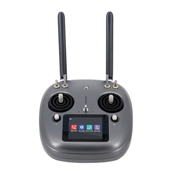
VD32 Remote Controller User Manual v1.2 2.2 Parts 2.2.1 At a Glance - 15 - 2020 SIYI Technology Copyright... - Page 16 VD32 Remote Controller User Manual v1.2 - 16 - 2020 SIYI Technology Copyright...
-
Page 17: Button/Switch Types And The Default Channel Definitions
VD32 Remote Controller User Manual v1.2 2.2.2 Button/Switch Types and the Default Channel Definitions VD32 transmitter has 16 channels in total. Each channel is controlled by an independent switch or button. Please refer to the form below for the default channel definitions from channel 1 to 16. -
Page 18: Sub-Trim Button
Mark: Self-locking button stays in the position you press them to; Self-resetting button rebound to original position after a press. Mark: VD32 transmitter supports customized channel definitions as well. Please refer to the chapter “SIYI TX APP” in this manual for detail. -
Page 19: Ports On Vd32
VD32 Remote Controller User Manual v1.2 ⚫ Sub-trim buttons can also be used to unlock transmitter system menu when the setting lock is turned on. Press and hold the two buttons to unlock transmitter. Mark: Please refer to “Sub-trim Settings” menu for trim settings. -
Page 20: Technical Specifications
VD32 Remote Controller User Manual v1.2 2.3 Technical Specifications Overall Channels 16 Channels Planes / Helicopters / Gliders / Quadcopters / Multi-rotors / Applicable Model Vehicles / Boats / Robots - 20 - 2020 SIYI Technology Copyright... - Page 21 VD32 Remote Controller User Manual v1.2 Open Source Flight Controllers: PIX/APM, etc. BOYING PALADIN V2 TOPXGUN T1-A Compatible FC WOOZOOM THEONE-A EFY FINIX200M JIYI K3A/K++ Model Data Memory 64 sets(extensible) Language Display Chinese / English Joystick Resolution 4096 grades Frequency Band 2.400 MHz - 2.483 MHz...
- Page 22 VD32 Remote Controller User Manual v1.2 Battery Type Chargeable Built-in 3.7V 8000mAh Li-Po 1S battery & Power 29.6 Wh Battery Life 8 Hours Battery Working 0 ~ 55 (℃) Temperature Charging Port Type Micro-USB; 5V/2A Charging Time 5 Hours Dimensions 184.5X180X114 mm...
-
Page 23: Packing List
VD32 Remote Controller User Manual v1.2 Operating Temperature -10 to 55 (℃) Dimensions 106 x 25 x 41 mm Net Weight 108 g 2.4 Packing List 1 x VD32 Transmitter 1 x VD32 Sky Station 1 x FPV Camera with Dual Navigation Lights... -
Page 24: Vd32 Common Diagram
VD32 Remote Controller User Manual v1.2 2.5 VD32 Common Diagram - 24 - 2020 SIYI Technology Copyright... -
Page 25: Transmitter Led Indicator Definition
VD32 Remote Controller User Manual v1.2 2.6 Transmitter LED Indicator Definition Each of the two LED indicators on VD32 transmitter has three colors and different blinking frequencies to indicate the transmitter’s different working status. Status Indicator Definition Solid Green: Transmitter works well. -
Page 26: Get Ready To Use Vd32
3 GET READY TO USE VD32 3.1 How to Place Transmitter Antenna Right Mark: VD32 transmitter has the best signal strength when the antennas are placed horizontally (A, B). Thus, please avoid pointing antennas’ upper end straightly to your aircraft and do not fold the antennas (C). -
Page 27: Good Antenna Angle Of Transmitter
VD32 Remote Controller User Manual v1.2 3.1.1 Good Antenna Angle of Transmitter - 27 - 2020 SIYI Technology Copyright... - Page 28 VD32 Remote Controller User Manual v1.2 Aircraft in front of the transmitter Aircraft up from the transmitter - 28 - 2020 SIYI Technology Copyright...
-
Page 29: Good Antenna Angle Of Receiver
VD32 Remote Controller User Manual v1.2 3.1.2 Good Antenna Angle of Receiver Flying high (Altitude higher than 10 meters, antennas should be placed downwards) Flying low (Altitude lower than 10 meters, antennas should be placed upwards) - 29 - 2020 SIYI Technology Copyright... -
Page 30: How To Charge Vd32 Transmitter
3.2 How to Charge VD32 Transmitter Before charging your VD32 transmitter, please read the part “1 READ TIPS - 1.3 Precautions on Charging VD32 Transmitter” carefully. -
Page 31: How To Link/Bind Vd30 Transmitter To Vd32 Receiver
Solid Green: Charging is finished. 3.3 How to Link/Bind VD30 Transmitter to VD32 Receiver Each unit of VD32 transmitter is assigned with a unique ID code. Before linking VD32 receiver to VD32 transmitter, the receiver identifies the transmitter ID (Linking/Binding) first. After the first linking process between the transmitter and the receiver is done, the transmitter ID will be memorized in the receiver so that you don’t have to repeat the process before the next flight/operation (except when your... - Page 32 2. In VD32 transmitter screen menu, tap on “System Settings – General Settings”; 3. Turn to your VD32 receiver, stick a pin or needle to the linking button inside the linking hole, press and hold the button for 3 seconds till the status indicator blinks red which means the receiver is ready for linking;...
-
Page 33: Throttle Joystick Type
VD32 transmitter supports both “Thumb-slide” and “Self-centering” throttle joysticks. Users decide which type to use according to their preference. Generally, if your VD32 transmitter has been set up as “Thumb-slide” throttle joystick, then the throttle type in “System Settings” should be “Thumb-slide” as well. - Page 34 VD32 Remote Controller User Manual v1.2 - 34 - 2020 SIYI Technology Copyright...
-
Page 35: Main Menu
4 MAIN MENU Model Name Displays the name of the selected model. Model Type Displays the selected model type. Battery Level Real-time display of VD32 transmitter’s battery level. Settings Approach to the “Transmitter Settings” menu. - 35 - 2020 SIYI Technology Copyright... - Page 36 The main menu is locked, the touchscreen is disabled (the icon disappears when main menu is unlocked). SD Card A SD card is inserted in VD32 transmitter (the icon disappears when the SD card is taken out). Timer Displays maximum two timers as to assist users with the flight.
-
Page 37: Model Settings
VD32 Remote Controller User Manual v1.2 5 MODEL SETTINGS In VD32 transmitter’s “Model Settings” menu, there are a series of useful functions, offering basic and advanced settings for different kinds of model devices. CH Monitor (Channel Monitor) Real-time display of all channels’ output value. - Page 38 VD32 Remote Controller User Manual v1.2 End Point Set the output values of a channel and the maximum / minimum limit. CH Mapping (Channel Mapping) Set / Change the defined function of a channel. CH Reverse (Channel Reverse) Reverse a channel’s output direction.
-
Page 39: Channel Monitor
VD32 Remote Controller User Manual v1.2 5.1 Channel Monitor In “Channel Monitor”, users can check the real-time changing of output values in all 16 channels. 5.2 Model Select “Model Select” function supports users to select, rename, copy and reset model data. -
Page 40: Select A Model
VD32 Remote Controller User Manual v1.2 5.2.1 Select a Model In VD32 transmitter’s default model list there are up to 64 sets of model data for your choice. Steps 1. In “Model Settings” menu, tap on “Model Select”, in the screen it shows the model select menu;... - Page 41 VD32 Remote Controller User Manual v1.2 Steps 1. Tap on a model name, then “Rename”, in the screen it pops up “Confirm to rename the model”; then “Yes”, in the screen it shows a virtual keyboard menu; 2. Input a new name for the model by using the virtual keyboard, then tap on “yes”...
-
Page 42: Copy A Model
VD32 Remote Controller User Manual v1.2 About Virtual Keyboard CAPS Switch keyboard to input capital letters. SCAP Switch keyboard to input lower case letters. Switch keyboard to input numbers and punctuations. Backspace Delete what is already input. Cancel Cancel inputting, the transmitter will not save the input. -
Page 43: Reset All Models
VD32 Remote Controller User Manual v1.2 2. Select the target model on the turntable, then tap on “Yes” to finish. 5.2.4 Reset all Models Users can reset all the data in the model list to the default settings. Steps 1. In the Model Select menu, tap on “Reset”, in the screen it pops up “Confirm to reset”;... -
Page 44: Model Type
2. Tap on “Yes” to finish. 5.3 Model Type In VD32 transmitter there are several default model types, Fixed-wings / Gliders, Multi-rotors (racing drones, agricultural drones) and the others (helicopters), each model type with its default settings done in advance. Users can choose a model type according to their requirement and customize the settings. -
Page 45: How To Select A Model Type
VD32 Remote Controller User Manual v1.2 CAUTION When you switch a model type, all the data in the current model will be reset automatically. It is better to save the model data before switching to another model type. 5.3.1 How to Select a Model Type Steps 1. -
Page 46: One Move To Do Agricultural Drone Settings
CAUTION Please make sure your VD32 transmitter and VD32 receiver are linked before doing agricultural drone settings. When the settings are done, please do not forget to re-calibrate your VD32 transmitter joysticks before unlocking motors and taking a flight. Steps 1. -
Page 47: End Point
Then Select the right FC and ESC type according to what you have bought. Please select “FOC” for ESC which is free of calibration. And select “Standard” for ESC which requires calibrating output value, then your VD32 transmitter will generate the channel value automatically according to your requirement. - Page 48 VD32 Remote Controller User Manual v1.2 1. Please refer to the picture below. In “Model Settings” menu, tap on “End Point”, in the screen it shows “End Point” menu (“-E.P.A+” stands for the channel value, “-limit / limit+” stands for the minimum/maximum limit value);...
-
Page 49: Channel Mapping
VD32 Remote Controller User Manual v1.2 5.5 Channel Mapping All 16 channels of VD32 transmitter can be mapped freely as you need to the joysticks, switches, buttons, and dials. Steps 1. Please refer to the picture above. Tap on the last box on right of your target channel to open the list of all joysticks, switches, buttons, and dials. - Page 50 VD32 Remote Controller User Manual v1.2 3. Let’s take example of Channel 1 (Aileron). Tap on the “J1” box on right of Channel 1 and select a joystick/switch/button/dial in the list. In the box it will show the selected joystick/switch/button/dial.
-
Page 51: Channel Reverse
Users can reverse a channel’s output direction through “Channel Reverse”. Steps 1. When your VD32 transmitter is linked to a new model, please confirm if all the servos, buttons, and switches have been mapped to right channels as you need. -
Page 52: Sub-Trim
VD32 Remote Controller User Manual v1.2 4. Please refer to the picture below. Tap on the “Normal/Reversed” box to switch the channel direction and the box will show if the channel is normal or reversed. Mark: Tap on “Reset” to reset all channels. - Page 53 VD32 Remote Controller User Manual v1.2 Before doing Sub-Trim settings, please make sure that the target Sub-Trim channel is in its middle position. CAUTION It is not a good idea to use Sub-Trim function when you are flying an agricultural drone.
-
Page 54: Trim Setting
That is, when Trim Setting value changes 5 units, the Trim Stepping value changes 1 unit. VD32 transmitter’s Trim Setting value is default to be 5, the minimum limit of the trim setting value is 0, the maximum limit is 100; the minimum limit of the trim stepping value is 0, the maximum limit is 20. -
Page 55: Trainer Mode
VD32 Remote Controller User Manual v1.2 2. Through Trim Settings function, users are able to adjust all 4 sub-trim channels; tap on a channel according to your requirement to change its trim stepping value; 3. Use the virtual turntable to select a target Trim Stepping value, the adjustable range is from 0 to 100;... - Page 56 The users can decide which channel to use for training. In the trainer mode, VD32 transmitter supports turning on/off the function through a physical switch or button. And users can switch the identity between trainer and student.
- Page 57 VD32 Remote Controller User Manual v1.2 4. The transmitter with the trainer mode turned on is the master transmitter, the other one is the slave transmitter; in the master transmitter the channel is default to be “Trainer”; 5. Each channel in the list has two status, trainer and student; if you change the status to “Student”...
-
Page 58: Fail Safe
VD32 Remote Controller User Manual v1.2 5.10 Fail Safe Before linking VD32 transmitter to VD32 receiver, do not forget to do fail-safe settings and turn on the function, thus if your transmitter lost linkage with receiver, fail-safe function will run automatically and immediately to protect your model from a crash. - Page 59 VD32 Remote Controller User Manual v1.2 3. Please refer to the picture below. Under fail-safe menu, the function is default to be off and it displays “HOLD” in each channel. Under this circumstance, if your transmitter lost linkage with sky station, the receiver will output the last channel value received from your transmitter.
-
Page 60: Timer
For flight safety, Fail-Safe settings must be done and the function must be turned on before taking-off. 5.11 Timer In VD32 transmitter main menu there are two timers. Timing Mode Up: Counts from 0, the timer alerts when it reaches the time. -
Page 61: Voltage Alert
VD32 Remote Controller User Manual v1.2 5.12 Voltage Alert When the user’s aircraft power voltage is lower than the safe level, VD32 transmitter will vibrate and send voice alert. Steps 1. In “Model Settings” menu, tap on “Voltage Alert”, in the screen it shows the voltage alert menu;... -
Page 62: Farming Voice
VD32 Remote Controller User Manual v1.2 5.13 Farming Voice Farming Voice is a professional function is for agricultural drones. The function is supported by up to 6 switches with 16 positions. They are SA, SB, SC, SD, S2 and Steps 1. - Page 63 VD32 Remote Controller User Manual v1.2 Voice List Atti. (Attitude): Attitude Mode Stab. (Stablize): Stable Mode Hold (AttiHold): Attitude Hold Mode GPS: GPS Mode AB Ln (AB Line): A/B Line Flight Mode Auto (AutoMode): Auto Flight Mode Rcd A (Record A): Record A Point...
-
Page 64: Joystick Dead Zone
LtOFF (LightOFF): Navigation light off 5.14 Joystick Dead Zone By setting a certain dead zone range, VD32 transmitter helps user filter out channel values which are input by touching the joysticks unintentionally. When the range is set, the channel value does not change if the joysticks stay moving in the range;... -
Page 65: Multi-Drone Control
2. Tap on the range, then “+/-” to input a target range according to your requirement; 3. Tap on “Return” to finish. 5.15 Multi-Drone Control Through one VD32 transmitter users can control up to three drones at the same time. Switch Drone The function is to switch the control of linked drones, from drone No.1 to No.3. - Page 66 VD32 Remote Controller User Manual v1.2 When the “Syn-control” function is activated, VD32 transmitter can control up to three drones at the same time. Under this circumstance, all drones fly at the same pace. The datalink only goes with one drone, which is the drone in control before activating the “Syn-control”...
-
Page 67: System Settings
VD32 Remote Controller User Manual v1.2 6 SYSTEM SETTINGS Functions General Stts (General Settings): Set transmitter’s basic functions Lock&Display (Screen Lock & Display): Turn on / off the display of the transmitter touch screen and adjust brightness H/W Settings (Hardware Settings): Change the hardware definition of several transmitter channels through software settings ExtPort Stts (Extending Ports Settings): Set the definition of the transmitter’s... -
Page 68: General Settings
ESC Cali: Calibrate ESC through PWM ports on the sky station 6.1 General Settings General Settings Menu Introduction Link (Linking): Start linking VD32 transmitter to receiver. Lang. (Language): Switch the system language between Chinese/English. Thrttl (Throttle Type): Switch the throttle joystick type between “Self-centering” and “Thumb-slide”. - Page 69 VD32 Remote Controller User Manual v1.2 Joystk (Joystick Mode): Switch the joystick mode from Mode 1 / Mode 2 / Custom. Vibrtn (Vibration): Turn on / off the vibration alert function. Voice (Voice Broadcast): Turn on / off the voice broadcast function.
-
Page 70: Screen Lock & Display
6.2 Screen Lock & Display Users can turn on / off the screen lock, set the waiting time, adjust the screen brightness and the screen sleep waiting time of VD32 transmitter. Screen Lock and Display Introduction Screen Lock: The touchscreen lock is disabled when the screen lock is enabled. -
Page 71: H / W Settings
VD32 Remote Controller User Manual v1.2 Mark: When the screen lock is enabled, press down a sub-trim button (LT5 direction of left sub-trim button, RT5 direction of right sub-trim button) for 3 seconds to unlock the screen. 6.3 H / W Settings... -
Page 72: Extending Ports Settings
6.4 Extending Ports Settings The extending ports function help users extend transmitter function to external hardware devices and SDK. Currently VD32 transmitter supports a Micro-USB port, a USB port and a 4-Pin Groove Port (DATA1). The Assigned Function to the Extending Ports Micro-USB: Charging, parameter adjustment, firmware upgrading and datalink output. - Page 73 4. Under “sky station”, the DATA1 port supports upgrading the sky station firmware; 5. Under “GPS” mode, the DATA1 port supports the GPS module. Agricultural drone pilots use the GPS module with VD32 transmitter to mark flight points; 6. Under “SDK”, the DATA1 port supports output of the joystick channel value. Tap on “+ / -”...
-
Page 74: Joystick Calibrating
VD32 Remote Controller User Manual v1.2 SDK Agreement Format Field Index Bytes Description 0X55 Data Length Data field byte length value: 32 CMD ID 0x00 Joystick channel data DATA Data type: 16-byte unsigned int for channel 1-16 Check Sum 8 bytes (check sum from 0 byte to 37 byte) 6.5 Joystick Calibrating... - Page 75 VD32 Remote Controller User Manual v1.2 Steps 1. In the system settings menu, tap on “Joystick Calibrating”, in the screen it shows the calibrating menu of the joystick; 2. The crossing coordinate system displays the real-time position of the joysticks;...
-
Page 76: Ld Calibrating
VD32 Remote Controller User Manual v1.2 6. When the detecting is finished, push both joysticks to the maximum position and move them in circle for several times; 7. Tap on “Finish” when it is over. 6.6 LD Calibrating Calibrating the left dial can maintain its output accuracy. The left dial requires calibration when it stays out of the middle position (channel value is not 0) or it fails to reach the maximum / minimum position. - Page 77 VD32 Remote Controller User Manual v1.2 LD calibrating menu; 2. Tap on “Start”, in the screen menu it shows “LD to the middle position”; 3. Make sure the left dial is in the middle position, then tap on “Next”; in the screen it shows “Calibrating LD’s middle position, do not move LD”;...
-
Page 78: Export/Import Setting Data
VD32 Remote Controller User Manual v1.2 6.7 Export/Import Setting Data Through the export setting function users can export the data of system settings and model settings to the SD card so as to share the data to another VD32 transmitter. Steps to Export Setting Data 1. - Page 79 VD32 Remote Controller User Manual v1.2 1. Connect VD32 transmitter to the computer via USB cable, and open the “SIYI Assistant” software; 2. Import the setting data saved in the SD card to the computer through a SD card reader, the files are in format “.CFG”. The data of the system settings is named as “SYS.CFG”, the data of all model settings is named as “ALL.CFG”;...
-
Page 80: Power Ratio
VD32 Remote Controller User Manual v1.2 6.8 Power Ratio 6.8.1 RF Power Power ratio function helps users adjust RF transmitting power output according to their requirement. Optional output power is 10dBm or 27 dBm. Steps 1. Power on the transmitter and sky station, make sure that they are linked with each other;... -
Page 81: Transmitter/Sky Station Antenna
VD32 Remote Controller User Manual v1.2 6.8.2 Transmitter/Sky Station Antenna Both the transmitter and the sky station have two antennas. Users can decide which antenna to use, the antenna 1, the antenna 2 or both according to their requirement. Steps to Choose the Antenna(s) 1. -
Page 82: Esc Cali
6.9 ESC Cali VD32 transmitter simplified the ESC calibration a lot. Users just connect their ESC to VD32 receiver’s PWM port 1 to 8, then follow the tips in the screen menu or the steps below to finish calibration. Steps to Calibrate the ESC 1. - Page 83 VD32 Remote Controller User Manual v1.2 on “Next”, the channel value of the transmitter throttle stick reaches to the minimum position automatically, and wait for the confirming sound again; The ESC calibrating is finished, you can cut off the power supply.
-
Page 84: Sky Station Settings
VD32 Remote Controller User Manual v1.2 7 Sky Station Settings Functions General Stts (General Settings): Set the basic functions of the sky station. Voltage Cali (Voltage Calibrating): Calibrate the voltage telemetry. PWM Settings: Change the channel definition under the PWM mode. -
Page 85: General Settings
VD32 Remote Controller User Manual v1.2 7.1 General Settings 7.1.1 Signal Mode Set signal mode for the three different output mode of the sky station, SBUS, PPM and PWM. Steps 1. In the general settings menu, select “Signal Mode” and tap on “SBUS / PPM / PWM”... -
Page 86: Voltage Telemetry
7.1.3 Voltage Telemetry When the voltage telemetry function is turned on, in the PWR (power) column of VD32 transmitter main menu, users can check the real-time display of the aircraft voltage telemetry. 7.1.4 RC Relay The function helps users with long distance flight relay. It supports two transmitters at most. -
Page 87: Voltage Calibrating
VD32 Remote Controller User Manual v1.2 2. Please link the transmitter 1 to the sky station first, then turn on “Remote Control Relay” in the “General Settings Relay” menu; the transmitter 1 is the slave transmitter; 3. Then link the transmitter 2 to the sky station; the transmitter is always the master transmitter even if you restart the sky station or transmitter. -
Page 88: Pwm Settings
7.3 PWM Settings In VD32 transmitter and the PWM mode, users can redefine the output channel of the sky station (channel 1-9 in default), so that if the channel 9 is already working in SBUS or PPM mode, the PWM ports 1 to 8 can still output to the channels 1 to... - Page 89 VD32 Remote Controller User Manual v1.2 16 of the transmitter. Steps 1. Power on the transmitter and the sky station, make sure that they are linked with each other; 2. The PWM port 1 of the transmitter is mapped to the PWM port 1 of the sky station, the PWM port 2 of the transmitter is mapped to the PWM port 2 of the sky station…and so on;...
-
Page 90: Video Transmission / Datalink Settings
VD32 Remote Controller User Manual v1.2 8 Video Transmission / Datalink Settings Functions Basic Stts (Basic Settings): Set basic functions of the datalink module. Advance Stts (Advanced Settings): Set the auto link function and the baud rate. Bluetooth: Choose the Bluetooth module for your flight controller. -
Page 91: Basic Settings
USB output, Micro-USB output and Bluetooth output. Flight Controller: Select a flight controller. VD32 transmitter supports all major flight controllers in market such as TOPXGUN (T1-A), WOOZOOM (THEONE-A), EFY (FINIX200M), BOYING (PALADIN), CHIAO (MATRIX), JIYI (K3-A), CFUAS (C1-A) and other flight controllers under open source Mavlink agreement such as PIX and APM. - Page 92 VD32 Remote Controller User Manual v1.2 CAUTION Before connecting the Micro-USB port of the transmitter to a smartphone or a tablet to communicate with the flight controller, you need to switch the port to Datalink. Steps In the “System Settings” menu, tap on “Port Settings”; tap on “Micro-USB” to switch the port to “Datalink”.
-
Page 93: Advanced Settings
VD32 Remote Controller User Manual v1.2 8.2 Advanced Settings If your flight controller type was not in the list, you can set a baud rate to match your flight controller. Steps Make sure that the sky station is linked with the transmitter; in the “Advanced Settings”... -
Page 94: Link Status
VD32 Remote Controller User Manual v1.2 8.4 Link Status The link status function helps users check the detail signal and link status of VD32 transmitter in real-time. 8.5 Video Transmission Settings Users can check the serial number of the video transmission module and power on/off the function. -
Page 95: Navigation Light
Steps to Upgrade Firmware and Voice Broadcast 1. Please visit SIYI Technology’s official website (http://www.siyi.biz); 2. In the product description page of VD32 transmitter, tap on “Downloads”; 3. Select the “SIYI Assistant” software, driver, the latest firmware and voice broadcast files, tap on “Download”;... - Page 96 VD32 Remote Controller User Manual v1.2 4. Unzip the files, install the “SIYI Assistant” and the driver to the computer; 5. When it is finished, use an USB cable, connect its one end to the Micro-USB port on VD32 transmitter, another end to the computer;...
-
Page 97: After-Sale Service
3. Find after-sale service center or technical support staff information and consult them with your product issue; 4. If the issue stays unsolved after confirming with SIYI Tech, then please refer to our after-service for filling in a “To-be-repair” form (personal repair form for individuals, distributor repair form for distributors);... -
Page 98: After-Sale Policy
It is requested beyond seven (7) calendar days of receiving a product. A product sent to SIYI for Return & Refund Service does not include all original accessories, attachments or packaging, or any item is not in new or like-new condition, i.e. -
Page 99: 15-Day Replacement
Damage is caused to the product by uncontrollable external factors, including fire, floods, high winds or lightning strikes. A product is not delivered to SIYI within seven (7) calendar days after Return & Refund Service confirmation is sent from SIYI. - Page 100 Legal proof-of-purchase, receipts, or invoices are not provided, or are reasonably believed to have been forged or tampered with. A product sent to SIYI for replacement does not include all original accessories, attachments and packaging, or contains items damaged by user error.
-
Page 101: 1-Year Warranty Repair
Charges may apply for services not covered by this Limited Warranty. Please contact SIYI for information specific to your location. Please note that the warranty service is only available in the respective SIYI service regions where you purchased your SIYI product. - Page 102 VD32 Remote Controller User Manual v1.2 Damage caused by unauthorized modification, disassembly, or shell opening not in accordance with official instructions or manuals. Damage caused by improper installation, in correct use, or operation not in accordance with official instructions or manuals.
- Page 103 VD32 Remote Controller User Manual v1.2 Products or parts with an altered identification label or from which the identification label has been removed. - 103 - 2020 SIYI Technology Copyright...
-
Page 104: Fcc Statement
VD32 Remote Controller User Manual v1.2 11 FCC STATEMENT This device complies with Part 15 of the FCC Rules. Operation is subject to the following two conditions: (1) This device may not cause harmful interference, and (2) This device must accept any interference received, including interference that may cause undesired operation. - Page 105 VD32 Remote Controller User Manual v1.2 determined by turning the equipment off and on, the user is encouraged to try to correct the interference by one or more of the following measures: Reorient or relocate the receiving antenna. Increase the separation between the equipment and receiver. Connect the equipment into an outlet on a circuit different from that to which the receiver is connected.
- Page 106 VD32 Remote Controller User Manual v1.2 SAR Information Statement The product is designed and manufactured not to exceed the emission limits for exposure to radiofrequency (RF) energy set by the Federal Communications Commission of the U.S. Government. These limits are part of comprehensive guidelines and establish permitted levels of RF energy for the general population.
Need help?
Do you have a question about the VD32 and is the answer not in the manual?
Questions and answers