
Subscribe to Our Youtube Channel
Related Manuals for ACO 8301A


Summary of Contents for ACO 8301A
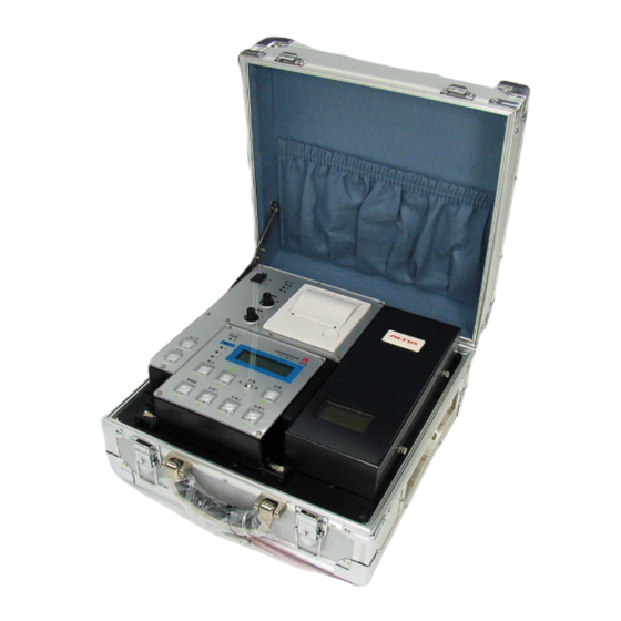
- Page 1 Instruction Manual Proximity Exhaust Noise Measuring System (Wireless) TYPE 8301A ACO Co., Ltd.
-
Page 2: Safety Precautions
Safety precautions To prevent bodily injury or damage to property, the following safety precautions must be observed. This manual contains important safety and operating instructions for this equipment. Read all instructions, before using the instrument. After reading all instructions, keep this manual for quick reference Expressions of safety instructions WARNING Calls attention to a procedure, practice, or condition that could possibly cause death or bodily... - Page 3 To reduce risk of injury, take it to a qualified serviceman when service or repair is required. Please contact ACO co. or the dealer when service or repair is required. Do not substitute parts or modify instrument. It causes bodily injury, fire or shock hazard.
- Page 4 Cautions for usage This equipment is assembled with precision parts. Placing it to a places such as exampled below may cause malfunction or failure, therefore care should be taken to avoid it. CAUTION Keep the instrument away from the children. If the instrument falls down, it is very dangerous.
- Page 5 4. Other cautions for usage Charge of the battery inside of the Proximity Exhaust Noise Measuring System * Remaining battery level right after the delivery or after long storage will be very low. Charge the battery once a month for about 10 hours. (Battery is needed even when the AC power is used.) * Do not charge over 12 hours to prevent the battery life becomes shorter.
- Page 6 12) For outdoor usage, place the case if front of the sunlight and adjust the position of the lid of the case by opening or closing between 45 degrees and 90 degrees to avoid direct sunlight. 13) For storage, avoid hot and humid place and store the system so that the rubber foots of the main body are touching the ground / shelf (vertical / horizontal).
-
Page 7: Table Of Contents
Contents ..........................1 AFETY PRECAUTIONS ....................1 XPRESSIONS OF SAFETY INSTRUCTIONS ......................2 MPORTANT SAFETY INSTRUCTIONS ..........................3 AUTIONS FOR USAGE INSTRUCTION MANUAL ......................3 ............................3 1. G ENERAL ............................3 2. F EATURES ........................... 4 3. C OMPONENTS ............................ -
Page 8: Cautions For Usage
INSTRUCTION MANUAL 1. General This document describes the instructions for operating Proximity Exhaust Noise Measurement System (wireless type). This is the system for measurement of automobile exhaust noise using the proximity exhaust noise measurement method in accordance with the safety standards for road transport vehicles (final revision : August 31, 2001, Ministry of Land, Infrastructure, Transport and Tourism ordinance No. -
Page 9: Components
* Microphone stand carrying case 1 ea * Accessories case 1 ea * Instruction manuals Proximity Exhaust Noise Measurement System (wireless type) Type 8301A 2 ea Operation guide for Proximity Exhaust Noise Measurement System (wireless type) Type 8301A 2 ea... -
Page 10: Names Of Each Part And Functions
5. Names of each part and functions 5-1 Proximity Exhaust Noise Measurement System main body <Main body panel> ⑨ ① ⑥ ② ③ ⑧ ④ ⑦ ⑤ ⑩ ⑩ ① Power ON/OFF : Power switch ② Sensitivity High / Medium / Low : For adjusting the input level of the pulse sensor ③... - Page 11 ⑥ Printer : Printer for printing the measurement results. ⑦ Sound volume meter LCD : LCD for displaying the sound level ⑧ Sound volume meter cover : Cover for the sound volume meter. Install by sliding it. ⑨ Battery level indicator : Displays the remaining level of the battery of the main body.
- Page 12 <Operation part (wireless)> ⑩ ⑨ ① ⑥ ③ ④ ② ⑧ ⑪ ⑤ ⑦ ① Calibration / : Switch for calibration. Perform calibration of sound volume meter (SV-6224) and revolution input circuit. ② Background noise / ▲ : Switch for background noise measurement. Background noise (noise before engine start) is measured.
- Page 13 <Right side panel (connection part for signal cables> ③ ② ① ① Microphone input : Connector for microphone extension cable. ② Pulse input : Connector for the pulse sensor IP-292 or IP-296. ③ AVL : Connector for AVL sensor. <Left side panel (connection part for power cables)> ④...
- Page 14 5-3 Arrow mark * Shall be level with the ground ① Arrow mark ② Windscreen ③ Microphone CAUTION ④ Microphone stand Be sure to attach the wind screen to the microphone.
-
Page 15: Preparation For Measurement
6. Preparation for measurement 6-1 Measurement flow Measurement is automatically performed with the following operations / displays. ① Turn ON the power switch. “Function” LED will be lit and then turned off System calibration after 3 seconds. ② Press calibration switch. ③... - Page 16 <Connection (Installation)> Proximity exhaust noise measurement system main body 45° Tachometer monitor to be Using the gauge of the microphone used for controlling the stand, adjust the positon to 50 cm accelerator. from the exhaust pipe opening and 45 degrees outside of exhaust gas flow direction.
-
Page 17: Connection Of The System (Installation
6-2 Connection of the system (installation) <Installation to the stand> Main body of the Proximity Exhaust Noise Measurement System shall be installed to the stand using 2 ea of fixing brackets. ①Put the main body of the Proximity Exhaust Noise Measurement System (wireless) on the table of the stand. -
Page 18: Removal Of Operation Part (Wireless)
6-3 Removal of operation part (wireless) Latch Latch Lever ① Raise the levers (2 places) and unlock the latches. ② The operation part (wireless) can be removed by pulling it toward you. ③ When installing the operation part (wireless), connect the connector of the operation part to the connector of the main body and lower the levers (2 places) and lock the latches. -
Page 19: Removal Of The Sound Volume Meter (For Using The Sound Volume Meter Individually)
6-5 Removal of the sound volume meter (for using the sound volume meter individually) Microphone cable Cover installation screw Sound volume meter Sound volume meter cover Cover installation screw ① Loosen two cover installation screws and remove the cover by pulling it to diagonally upward on the right side. -
Page 20: Measurement Power On
7. Measurement 7-1 Power ON Confirm that the batteries of the main body of the Proximity Exhaust Noise Measurement System and the operation part (wireless) are fully charged. 1) Battery built in to the main body of the Proximity Exhaust Noise Measurement System. For the built-in battery, confirm by the battery level indicator on the main body panel. - Page 21 2) Operation part (wireless) re-chargeable battery At the time of power ON, confirmation of sound volume meter and remaining level of operation part (wireless) re-chargeable battery will be automatically performed. If it is confirmed that there is no anomaly, display will turn to initial screen. Be sure that power ON is be made after the operation part (wireless) is installed to the main body.
- Page 22 3) Stand-by screen After normal start-up the display will turn to stand-by screen. Sensor lamp Blinks regularly. ← Calendar ← Inspection revolution speed and measurement revolution speed ← Engine type, sound volume value ← Status * Calendar will be updated every 1 minutes. * With the input of the revolution signal, buzzer will beep regularly and the sensor lamp will blink regularly at the same time.
-
Page 23: Setting Measurement Conditions
7-2 Setting measurement conditions At stand-by screen, press “Function” switch (LED will be lit) and following measurement conditions setting screen will be displayed. To return to stand-by screen, press “SET” switch at the measurement conditions setting screen. Function switch 1. STD-RPM : Set reference revolution speed and tolerance for measurement 2. - Page 24 7-2-2 Setting method for engine type 1) Press “Function” switch and select [2] using [▲][▼] switches, and press “Function” switch. 2) Select engine type using [▲][▼] switched and press “SET” switch. ←Engine type Engine can be selected from following 18 types. Pulse sensor RTE3 : For Rotary engine vehicle RTE2...
- Page 25 7-2-3 Setting method for time correction 1) Press “Function” switch and select [3] using [▲][▼] switches, and press “Function” switch. ← Year / Month / Day Time 2) With the date and time displayed on the screen, move the cursor to desire value to change by [ ][ ] and change the value using [▲][▼] switches and set by “SET”...
- Page 26 7-2-5 List of environment setting items “Function” STD・RPM 5000 RPM 9% 450 RPM (Engine revolution speed at measurement) TIME 14/11/30 12:00 (Calibration of date, clock) ENGIN RTE - 1 (Rotary engine 1) RTE - 2 (Rotary engine 2) RTE - 3 (Rotary engine 3) S4C1 (4 cycle engine, secondary side)
-
Page 27: Calibration
7-3 Calibration 1) Setting Perform calibration without connecting the tachometer sensor and with following switch positions. * “Sensitivity” switch High * “Polarity” switch * “AVL” switch OFF (Lamp off) 2) Calibration At the stand-by screen, press “Calibration” switch to start the calibration. Revolution speed indicates 2000 rpm. - Page 28 7-4 Installation of revolution sensor 7-4-1 Sound-vibration type AVL sensor This sensor can be used for many vehicles with gasoline engines and diesel engines. Microphone Magnet with built-in accelerometer Installation procedure ① Connect to “AVL” connector on the side of the Proximity Exhaust Noise Measurement System main body.
- Page 29 7-4-2 Non-contact type pulse sensor This sensor is used mainly for the measurement for vehicles of 2 cycle / 4 cycle gasoline engine with distributor type ignition system. 1) Installation procedure ① Slide the bunchy part ① on the upper surface of the sensor and the core at the tip will be opened.
-
Page 30: Measurement Of Background Noise (Engine Stopped)
7-5 Measurement of background noise (engine stopped) After the measurement of background noise, measurement will be automatically started with the measurement method set by the measurement A / B. Result of the background noise measurement will be retained until the start of next background noise measurement, or until the power is turned OFF. -
Page 31: Measurement By Measurement Methoda
7-6 Measurement by measurement method A Measurement will be started with measurement method A when “Measurement A / B” switch is set to “A”. “Measurement A / B” switch shall be set before pressing “Background noise” switch, or before pressing “Measurement 1” switch. If “Measurement 1”... - Page 32 CAUTION Confirm that the LED of “AVL” switch on the main body panel is lit while AVL sensor is used. The LED of AVL sensor is firstly lit in red and then it will be lit in yellow after 3 to 20 seconds. If it is not lit in yellow, check the installation or change the position.
- Page 33 3) Measurement of “Measurement 2” If “Measurement 2” switch is pressed during the measurement, measurement will be interrupted and “!! Pause !!” will be displayed. Press “Measurement 2” switch again and the measurement will be resumed. If “Background noise” switch is pressed, the measurement will return to background noise measurement.
-
Page 34: Measurement By Measurement Methodb
7-7 Measurement by measurement method B Measurement will be started with measurement method B when “Measurement A / B” switch is set to “B”. “Measurement A / B” switch shall be set before pressing “Background noise” switch, or before pressing “Measurement 1” switch. If “Measurement 1”... - Page 35 2) Engine start and measurement of “Measurement 1” If “Measurement 1” switch is pressed during the measurement, measurement will be interrupted and “!! Pause !!” will be displayed. Press “Measurement 1” switch again and the measurement will be resumed. If “Background noise” switch is pressed, the measurement will return to background noise measurement.
- Page 36 ④ Release the accelerator gradually and when it reaches the engine speed indicator LED for idling, measurement result of “Measurement 1” will be displayed for 1 second. Then the LED for “Measurement 2” will be automatically lit and measurement of “Measurement 2”...
- Page 37 ← Display measurement result 4) Measurement of “Measurement 3” If “Measurement 3” switch is pressed during the measurement, measurement will be interrupted and “!! Pause !!” will be displayed. Press “Measurement 3” switch again and the measurement will be resumed. If “Background noise” switch is pressed, the measurement will return to background noise measurement.
-
Page 38: Printing Method
Example of print ← Date and time ← Set revolution speed ← Background noise ← Result of “Measurement 1” in 1 place after the decimal point. ← Result of “Measurement 2” in 1 place after the decimal point. ← Result of “Measurement 3” in 1 place after the decimal point. -
Page 39: Specification
8. Specification Compatible vehicle type : 2 cycle or 4 cycle gasoline engine vehicle, diesel engine vehicle, rotary engine vehicle Built-in sound volume meter : SV-6224 Measurement item : Background noise level Average of ambient sound level for 10 seconds while the engine of the subject vehicle is stopped. - Page 40 Maximum sound level for the third measurement (for measurement method B only) Arithmetic mean value for the first and second measurements (for measurement method A only) Arithmetic mean value for the first, second and third measurements (for measurement method B only) Engine tachometer : 300 rpm ~ 9,999 rpm, detection accuracy ±...
- Page 41 (Arithmetic mean value for two measurements is 0.1 dB unit) Measurement method B ; 0.1 dB unit, 1 second interval (Arithmetic mean value for three measurements is 0.1 dB unit) Engine revolution speed ;4 digits, 1 rpm unit, 1 second interval 12) Engine revolution speed monitor lamp : Displays engine revolution speed against measurement revolution speed in 5 steps...
- Page 42 19) Dimensions and weight (main body) : Approx 350 mm (D) × 350 mm (W) × 180 mm (H), approx. 10 kg. 20) Operation, control, display part construction : Integrated singled body construction with wireless system (remote control is possible by removing from the main body)
Need help?
Do you have a question about the 8301A and is the answer not in the manual?
Questions and answers