Table of Contents
Advertisement
Quick Links
Advertisement
Chapters
Table of Contents

Related Manuals for ACO 3116


Summary of Contents for ACO 3116
- Page 1 Compact Size Vibration Meter TYPE 3116 Instruction Manual ACO Co.,Ltd.
- Page 2 Composition of this Instruction Manual This Instruction Manual explains the function and the operation method, etc. of Compact size Vibration Meter TYPE3116. Be sure to read the handling description of the apparatus concerned, when constructing with other apparatus and measuring. Moreover, be sure to read notes about the safety indicated after the following page.
-
Page 3: 1.Expressions Of Safety Instructions
To prevent bodily injury or damage to property, the following safety precautions must be observed. This manual contains important safety and operating instructions for Compact Size Vibration Meter TYPE 3116. Read all instructions, before using the instrument. After reading all instructions, keep this manual for quick reference 1.Expressions of safety instructions... -
Page 4: 3.Cautions For Usage
Turn off the POWER switch and unplug the AC adapter (optional) from outlet as soon as possible. To reduce risk of injury, take it to a qualified serviceman when service or repair is required. Please contact ACO co. or the dealer when service or repair is required. -
Page 5: Table Of Contents
Contents ..........................2 AFETY PRECAUTIONS 1.Expressions of safety instructions ....................... 2 2.Important safety instructions ........................3 3.Cautions for usage ............................3 .............................. 4 ONTENTS OVERVIEW ..........................5 Features ................................5 Configuration ..............................5 ............................5 UARANTEE NAMES AND FUNCTIONS OF VARIOUS PARTS ............... 6 Front .................................. -
Page 6: Overview
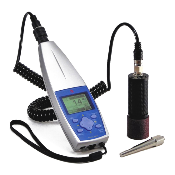
Overview Vibration Meter “ACO VIBRO TYPE3116” is super mine-size like a cellular phone. It offers, just like a “machinery doctor”, high precision monitoring of various industrial machinery by using the optional headphone or auscultation stick It offers a simple way of making medical chart for your machine The “data hold”... -
Page 7: Names And Functions Of Various Parts
Names and functions of various parts Front Input terminal Display Light Power Cursor button MENU Save/Set Hand strap Input terminal It is the terminal which connects pickup TYPE 7812B in attached connection code. Display The setting status of measured value and various switches are displayed. Power Long-pressing this switch for 1 sec or more turns on the power. - Page 8 Names and functions of various parts Menu It pushes, when setting up measurement conditions. Calendar adjustment etc. There are three Menu screens to 1/3-3/3. If it pushes 4 times, it will return to a standard screen. **** is a setting value at the time of factory shipments. :Manu ;Measurement Menu 1/3...
-
Page 9: Base
Names and functions of various parts Base AC Adaptor terminal Mating connector Type:MP-121WH Manufacturer:MARUSHIN ELECTRIC MFG. CO.,LTD Plug Type:φ3.4×1.4 Polarity;Outside+ Interface connector AC/Headphone output terminal AC Adapter Terminal (External Power Source Contact Terminal; EXT/DC) Connect to AC Adapter AC-1046(Option) ! CAUTION ●... -
Page 10: Background
Names and functions of various parts Background Name plate Battery holder (2 Alkaline dry cells typeLR03) Name plate You can see a name, Type, Serial No. and Date of Manufacture etc.. Battery holder 2 Alkaline dry cells type LR03. ― 9 ―... -
Page 11: Accelerometer
Type F Connector Accelerometer TYPE 7812B BNC Connector Connect to Input Terminal of Main Body TYPE 3116 ! CATUION ● The connection connector of a main body and a curl cable is an one-touch type BNC connector. Please do not turn by the connector part the time of connection, or after connection. -
Page 12: Description Of Screen
Description of Screen Standard screen ① ⑧ 136.0 ② ⑨ ③ ④ Range ⑤ ⑩ 000/000 ⑥ ⑦ ① Output Mode Display the Output mode of Headphone output terminal on the base. :Waveform output Level ADJ :Headphone output -3,-2,-1,0,+1,+2,+3 A waveform signal is outputted when Menu 3/3 Moni / Level is “AC”. Moreover, you can act as the monitor of the vibration value which plug adapter PC-260MS connect with portable headphone ATH-FC5 BK of an option at the time of a level ADJ "-3 and –2・・・・+3". - Page 13 Description of Screen ⑦ Display of state no display :Normal display :Blinking Over display :Blinking Data save Hold Memory :Blinking Memory display mode Save :Blinking Turn off after selected cursor button ⑧ Display the condition of the batteries Display the condition of the batteries. Reference to Battery installation P14 ~ 15. ⑨...
-
Page 14: Menu Screen
Description of Screen Menu screen It pushes, when setting up measurement conditions. There are three Menu screens. If it pushes 4 times, it will return to a standard screen. **** is a setting value at the time of factory shipments. Menu 1/3 <Menu>... -
Page 15: Preparation
Preparation The required matter is indicated before beginning measurement. Please do at a position of power switch is off at the time of set the battery and connection cords. Power It operates by two alkaline dry cells type LR03 or AC adapter AC-1046 (option). Battery installation When the unit is in operation, turn off the power by pressing the Power... - Page 16 Preparation 3)Long-press the Power button for 1 sec or more. Power Type 3116 Ver. 2.1 2000/01/01 00:00:00 Start Screen The indicator is shown battery remaining capacity on the upper right of a display screen. Battery remaining capacity 136.0 Range 000/000 The following displays tell you the condition of the batteries.
-
Page 17: Connection Of A Connection Code
Preparation Connection of a connection code 1)When the unit is in operation, turn off the power by pressing the switch. Power Acceleration pickup TYPE 7812B and Compact size vibration meter TYPE3116 are connected by curl cable as shown in the following figure. 2)The BNC connector of a curl cable is connected to the input terminal of a main part. -
Page 18: Attachment Of An Acceleration Pickup
Preparation Attachment of an acceleration pickup There are some methods of attachment to the measurement subject of Accelerometer. Contact resonance frequency * changes with the attachment methods of an Accelerometer sharply. Please perform suitable attachment in consideration of the advantage and fault of each attachment method *Contact resonant frequency and the high region characteristic If an Accelerometer is attached in a measurement subject, one vibration system will be... - Page 19 Preparation Fixation with a screw The usage which fixes an acceleration pickup with a screw is the most fundamental method, and its oscillation characteristic is the best Please make 0.4a-1.6a to the surface of an attachment side. Please fasten the bolting torque with an Accelerometer Accelerometer, an attachment screw, and TYPE 7812B...
- Page 20 Preparation Forcing by the contact pin Measure in the place of an unfixable narrow place or a thin pipe where does not have sufficient contact surface product using a contact pin. Although it is the easiest method, 500 or more Vibration measurement cannot be performed because Contact Resonant Frequency falls very much, Please fasten the bolting torque of an Accelerometer and Contact pin by 1 - 1.5...
-
Page 21: Setting
Setting Setting mode Whenever it pushes a Menu button, standard screen ( measurement screen ) → MENU 1/3 → MENU 2/3 → MENU 3/3 → standard screen ( measurement screen ) it changes. The four directions of cursor button Menu Calendar adjustment To adjust the calendar (time), operate as follows. -
Page 22: Lcd Contrast Adjustment
Setting 4)If you want to go back to the measurement mode, pressing it three times returns to the Menu button. LCD contrast adjustment You can adjust LCD contrast, when the batteries were low, or when the new batteries were installed. The procedure is as follows. The four directions of cursor button Menu Save/Set... -
Page 23: Measurement
Measurement Power ON 1) Long-press the Power button for 1 sec or more. Immediately after the power goes on, the following screen is displayed: Power Type 3116 Ver. 2.1 2000/01/01 00:00:00 Start Screen After about 5 seconds 136.0 Range 000/000... -
Page 24: Measurement Of Acceleration (Acc)
Measurement Measurement of acceleration (ACC) Just after power supply on, it starts with the acceleration measurement mode mentioned above. The current value is displayed in digital form at an interval of 1 sec and a bar at an interval of 0.1 seconds. -
Page 25: Measurement The Displacement(Disp
Measurement < Change of the Measurement Range > 1)Select the command with cursor button again, the Range change to Mode. 2)Operated so that a level may become a legible value with cursor button (Number on the right of a bar It change with 200 → 20 → 200.) Since [OV] (Overload) is displayed when a value is large, a range is adjusted. -
Page 26: Data Recording
< Change of the Detector > 1)When you want to change the mode and measure,(RMS/PEAK)、display the "Peak/RMS" by the command selection cursor button , and changes by the cursor button Whenever it pushes, the mode changes with RMS → Peak → EQPeak → RMS. 2)It is pressing cursor button and display can be Hold(ed) to fix a display value. -
Page 27: Data Call
Measurement Data call You can see the recorded data with Meas of Menu 1/3 is set to Mem Call. 01/01 12:01 136.0 Cursor button Menu Range 016/016 Memory RMS Save/Set Display of a state The recording number 1) When you press the Menu button the following screen appears. -
Page 28: Data Deletion
Measurement Data deletion You can see the recorded data with Meas of Menu 1/3 is set to Mem Clr. 01/01 12:01 136.0 Cursor button Menu Range 016/016 Memory RMS Save/Set Display of a state The recording number 1) When you press the Menu button the following screen appears. -
Page 29: Output Signal
Measurement Output signal Using AC / Portable headphone output terminal which is the bottom of a main part can observation and record output signal. AC / Portable headphone output terminal A waveform signal is output when Menu 3/3 Moni/Level is AC. AC output mode 136.0 Cursor button... -
Page 30: Reference 1
Reference 1 Velocity(VEL)Frequency characteristics JIS Standards レ ス ポ ン ス (dB) 1000 10000 周波数(Hz) Frequency (Hz) *This inside of a dotted line with a velocity of 10-1kHz satisfies the frequency range about mechanical vibration of rotating for vibration severity of JIS B0907~1989. ―... -
Page 31: Handling Of An Option Article
Turn off the POWER switch and unplug the AC adapter (optional) from outlet as soon as possible. To reduce risk of injury, take it to a qualified serviceman when service or repair is required. Please contact ACO co. or the dealer when service or repair is required. -
Page 32: Set Up Of Rs-232C
Handling of an option article Set up of RS-232C Set up the RS-232C by Menu 3/3 baud rate of a main body. 1)It is made a screen. <Menu 3/3> with push 3 times Menu Cursor button 4 direction Menu Save/Set 2) Select baud rate with Cursor button , then move the cursor rightward with cursor button... -
Page 33: Connection With A Pc
Handling of an option article Connection with a PC When connecting a main part and a personal computer by BC-0026PC as shown in the following figure. Set up of RS-232C Set up the RS-232C by Menu 3/3 baud rate of a main body. 1)It is made a screen. -
Page 34: Detail Specification Of Communication Command
Data size ;1it Stop bit Parity check ;non Transfer Speed ;4800,9600,19200bps →Selected in TYPE 3116/3116A Flow control ;non 2.Data Specification All the data are outputted in ASC II format. The PC software needs ‘Time Out’ function. ① 001/256 + LF :Measurement No. - Page 35 7) Confirm the completion of data transfer by checking the last data No. ex) 001/256 ・・・256/256(as in the case of 256 data) TYPE 3116/3116A will finish by itself (No handshake) 8) In the case of data error, cancel the program.
-
Page 36: Data Managed Software
Data managed software It is possible to manage the data on your PC by using the data handling software. ● Data sampling and vibration data display for Vibration meter TYPE 3116 through serial data communication. ● The data is stored in CVS form, corresponding to data processing of spreadsheet software. -
Page 37: Specification
Specification Accelerometer TYPE 7812B specification 1)Sensor :Voltage output type( built-in pre-amplifier) 2)TYPE :7812B 3)Sensitivity :5.0mV/m/s (49.1mV/G)±3% at 100Hz 4)Transverse Sensitivity :5% or less 5)Frequency characteristics :1Hz~8kHz 6)Constant-current supply :DC7V0.5~4mA 7)Temperature range :-10~+60℃ 8)Size and Weight :24φ×50 Approx.60g Specification Measurement range 2... -
Page 38: Reference 2
Reference 2 Relation between indicated value and AC output The relation between full scale indicated value and AC output voltage at output terminal, in each Measurement mode and Range, are shown as in the following table. Full scale Output Voltage Measurement Range Data mode... -
Page 39: Relationship Between The Maximum Measurement Range And Frequency
Relationship between the maximum measurement range and frequency The maximum measurement range of this instrument is, as shown in the vibration monograph (rms value) below, dependent upon the acceleration (ACC) and frequency. Setting of the range at velocity (VEL) and displacement (DISP) modes shall be made by acceleration (ACC). If acceleration (ACC) exceeds 20 m/s , make sure to use 200 mm/s range for the velocity (VEL), and 2000μm range for the displacement (DISP). -
Page 40: A Trouble And The Processing Method
A trouble and the processing method 【Power】 Trouble Cause The processing method The battery is exhausted. Exchange Batteries. The polarity of a battery is set Reset Batteries correctly. conversely. It was not long-pressing the Long-pressing the This meter does not operate, Power button. -
Page 41: How To Connect/Disconnect The Cable
② ① ① Hold up 3116 main body and BNC one-touch connector of curl cable to fit mark of BNC connector to the boss of the main body. ② Push straight the BNC one-touch connector into the main body unit it clicks. - Page 42 2)How to connect/disconnect F-type connector of curl cable. F-type Connector Accelerometer Accordion portion TYPE 7812B Curl cable Hold up only F-type connector to turn it clockwise into the Accelerometer. <Connection> ① ② ① Hold up Accelerometer and F-type connector of curl cable to fit each other. ②...
- Page 43 How to Measure Vibration meter using 3116 1.Setting up 1-1 Battery installation This operates with two alkali dry cells (LR03) or an AC adaptor AC-1046 (Option). 1)When the unit is in operation, turn off the power by pressing the Power switch.
- Page 44 Battery installation The indicator is shown battery remaining capacity on the upper right of a display screen. Battery remaining capacity 136.0 Range 000/000 The following displays tell you the condition of the batteries. EMPTY Full Replace batteries When LCD display tells low battery, install new batteries. For long-term measurement, install new batteries in advance.
- Page 45 2.Panel Button operations and Function・Screen display explanation 2-1 Panel Button operations ④ ① ⑦ ⑥ ③ ② ⑤ ① Power :Long-pressing this switch for 1 sec or more turns on the power. Long-pressing it again turns off the power. ② :Record at the time measurement, and the setting button used when Save/Set the Menu screen is operated.
- Page 46 3.Measurement 3-1 Measurement of acceleration (ACC) Just after power supply on, it starts with the acceleration measurement mode mentioned above. The current value is displayed in digital form at an interval of 2 sec and a bar at an interval of 0.1 seconds.
- Page 47 3-2 Measurement the velocity(VEL) The current value is displayed in digital form at an interval of 2 sec and a bar at an interval of 0.1 seconds. Change the mode and the value 136.0 Measurement value Mode Select The command Measurement Range Range 000/000...
- Page 48 < Data Recording > It is inputting Save/Set and can record at any time to record data. 1)Push the Save/Set blinks Save. 2)Select the recording number with cursor button 016/016 Total data The recording number 3)It will be recorded if Save/Set is pushed again (a Save display disappears).
- Page 49 5.Calendar adjustment To adjust the calendar (time), operate as follows. You can adjust calendar in the [Menu] mode in the same way as LCD adjustment. <Menu> Meas :Manu :OFF Date adjustment Date :00/00/00 Time adjustment Time :00:00:00 【Calendar adjustment】 1)When you press the Menu button the following screen appears.
- Page 50 ACO VIBRO TYPE 3116 Data management software NA-0116 Operating manual ACO CO., LTD.
- Page 51 3.3.1 Starting window(Collection/Data Registration)............. 7 3.3.2 Folder ........................7 3.3.3 Communication setting .................... 8 3.3.4 Set up RS-232C of TYPE3116 .................. 9 3.3.5 Connection(Data reception, data registration of TYPE 3116) ......10 3.3.6 Raw data storage ....................13 ......................15 REND DISPLAY...
-
Page 52: Installation
ACO NA-0116 comdlg32.ocx MSCOMM32.ocx MSFLXGRD.ocx richtx32.ocx Type 3116E Ver1.0.EXE ・・・・・・・・・・ Managed software for TYPE 3116 Manual. PDF(present volume) 2) Insert the attached CD-ROM into the CD-ROM drive. 3) Copy all files in “ACO NA-0116” to any place (drive / the folder). -
Page 53: Connection Of Pc And Type 3116
To connect PC and Type 3116, use interface cable BC-0026PC as follows: Interface connector Interface cable BC-0026PC To RS-232C 2) When using BC-0026 To connect PC and Type 3116, use interface cable BC-0026 and conversion connector A12-25F-9F (option) as follows: Interface connector Interface cable BC-0026 To RS-232C... -
Page 54: Windows And Operation
: Used to save the collected data in CSV file. Raw data display : Used to display the collected data saved in CSV form. Data Communication setting : Sets and displays the condition of data communication. Connection : Connects the data folder with Compact Size Vibration Meter TYPE 3116. -
Page 55: Apparatus Registration
Data management software NA-0116 3.2 Apparatus registration 3.2.1 Apparatus registration When used for the first time, or for setting-up new management items (a name, object apparatus, etc.), the apparatus must be registered. 1) Click [Apparatus registration] button 2) The [Apparatus registration] window will show up as blows: 3) Select the drive. -
Page 56: Apparatus Registration Hierarchy Of Folders
Data management software NA-0116 3.2.2 Apparatus registration hierarchy of folders Apparatus registration hierarchy of folders is as following. Folder Plant Apparatus Unit No. Measurement spot and direction Acceleration Peak EQPeak Velocity Peak EQPeak Displacement Peak EQPeak EQp-p... -
Page 57: Collection/Data Registration
Data management software NA-0116 3.3 Collection/Data Registration 3.3.1 Starting window(Collection/Data Registration). 1) Opening “Type3116E Ver1.0.EXE” starts up Data Management Software TYPE3116. 3.3.2 Folder 1) Select the right folder by clicking at [Folders] button. In the same way, select [Plant], [Apparatus], [Unit No.], [Measurement part and direction] and [memo]. -
Page 58: Communication Setting
NA-0116 3.3.3 Communication setting 1) Click the [Communication setting] button. 2) Select each item so that all the conditions of your PC meets those of TYPE 3116. In the case above: Port No.:COM1, Baud rate:9600 3) Click [OK] button to finish the selection and to return to the starting window. -
Page 59: Set Up Rs-232C Of Type3116
Data management software NA-0116 3.3.4 Set up RS-232C of TYPE3116 Set up RS-232C with Menu 3/3 baud rate. 1) Press Menu button three times to reach the <Menu 3/3> window. Cursor button Menu Save/Set 2) Select baud rate with cursor button , and move the cursor rightward with cursor button <Menu>... -
Page 60: Connection(Data Reception, Data Registration Of Type 3116
Data management software NA-0116 3.3.5 Connection(Data reception, data registration of TYPE 3116) 1) Click [Connection] button. The display changes to [Waiting for data]. 2) Press [Menu] and <Menu 1/3> window appears. Cursor button Menu Save/Set 3) Select I/O with Cursor button , and move the cursor rightward with cursor button <Menu>... - Page 61 7) On the completion of data transmission, the collected data are displayed. If you do not register the data and need to repeat the date collection or to collect the data from other TYPE(s) of 3116, you have only to click [Collection/data registration] button and [Connection] button.
- Page 62 Data management software NA-0116 8) Click [Raw data storage] button to give a file name and to save it by [save] button. 9) Click [Quit] button to close the software.
-
Page 63: Raw Data Storage
Data management software NA-0116 3.3.6 Raw data storage 1) Start the software and click [raw data display] button. 2) Select the data and click [open] button. - Page 64 Data management software NA-0116 3) Click and select data you want to register. On Selection the color of the line changes and [*] mark left. 4) Click [data registration] button to register the data. Folder selection and registration are available for each data. On selection or registration, a flag is attached to the head.
-
Page 65: Trend Display
Data management software NA-0116 3.4 Trend display Click [Trend display] button to display the graphic data stored in the folder. Change Display Position Display mode Cursor Y-axis Multiplier Measurement mode X-axis Multiplier Cursor move Bar Measurement value display 1) Change Display Position Change the position to be displayed.
Need help?
Do you have a question about the 3116 and is the answer not in the manual?
Questions and answers