Subscribe to Our Youtube Channel
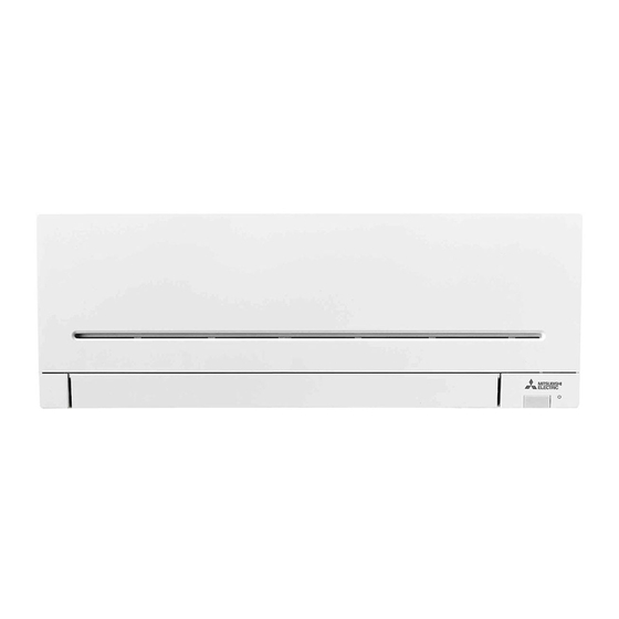
Summary of Contents for Mitsubishi Electric MSZ-AP15VGD
- Page 1 SPLIT-TYPE AIR CONDITIONERS MSZ-AP15VGD MSZ-AP20VGD For INSTALLER INSTALLATION MANUAL English • This manual only describes the installation of indoor unit. When installing the outdoor unit, refer to the installation manual of outdoor unit.
-
Page 2: Table Of Contents
FOR INSTALLER Required Tools for Installation CONTENTS Phillips screwdriver 4 mm hexagonal wrench Level Flare tool for R32, R410A 1. BEFORE INSTALLATION ........1 When installing multi units, Scale Gauge manifold for R32, R410A 2. INDOOR UNIT INSTALLATION ......4 refer to the installation Utility knife or scissors Vacuum pump for R32, R410A 3. - Page 3 Breaker Indoor/outdoor charge *8 Indoor unit Outdoor unit Frequency Power supply *2 Gas / Liquid Voltage capacity connecting wire *2 MSZ-AP15VGD 50/60 Hz 4-core ø9.52 / 6.35 mm 230 V 1.0 mm² (0.8 mm) MSZ-AP20VGD 3-core MUZ-AP20VG 50 Hz 10 A 810 g 1.0 mm²...
- Page 4 1-4. INSTALLATION DIAGRAM ACCESSORIES PARTS TO BE PROVIDED AT YOUR SITE Check the following parts before installation. (A) Indoor/outdoor unit connecting wire*1 <Indoor unit> (B) Extension pipe (1) Installation plate (C) Wall hole sleeve (2) Installation plate fixing screw 4 × 25 mm (D) Wall hole cover (3) Wireless remote controller (E) Pipe fixing band...
-
Page 5: Indoor Unit Installation
2. INDOOR UNIT INSTALLATION 2-1. FIXING OF INSTALLATION PLATE 2-4. PIPE FORMING AND DRAIN PIPING • Find a structural material (such as a stud) in the wall and fix installation plate Pipe Forming • Place the drain hose below the refrigerant piping. (1) horizontally by tightening the fixing screws (2) firmly. -
Page 6: Outdoor Unit Installation
3. OUTDOOR UNIT INSTALLATION 3-1. CONNECTING WIRES FOR OUTDOOR UNIT A (mm) Tightening torque 1) Open the service panel. Clutch Clutch Wing Pipe diameter 2) Loosen terminal screw, and connect indoor/outdoor unit connecting wire (A) type type nut type (mm) (mm) from the indoor unit correctly on the terminal block. -
Page 7: Purging Procedures, Leak Test, And Test Run
3-5. CONNECTING THE INTERFACE/CONNECTOR CABLE TO THE AIR CONDITIONER • Connect the INTERFACE/CONNECTOR CABLE to the Indoor electronic control P.C. board of the air conditioner with the connecting cable. • Cutting or extending the connecting cable of the INTERFACE/CONNECTOR CABLE results in defects in connecting. Do not bundle the connecting cable together with power supply cord, Indoor/outdoor connecting wire, and/or earth wire. -
Page 8: Relocation And Maintenance
4-2. TEST RUN 4-3. AUTO RESTART FUNCTION 1) Insert power supply plug into the power outlet This product is equipped with an auto restart function. When the power and/or turn on the breaker. supply is stopped during operation, such as during blackouts, the function 2) Press the E.O. - Page 12 This product is designed and intended for use in the residential, commercial and light-industrial environment. HEAD OFFICE: TOKYO BUILDING, 2-7-3, MARUNOUCHI, CHIYODA-KU, TOKYO 100-8310, JAPAN VG79J830H01...


Need help?
Do you have a question about the MSZ-AP15VGD and is the answer not in the manual?
Questions and answers