Table of Contents
Advertisement
LG
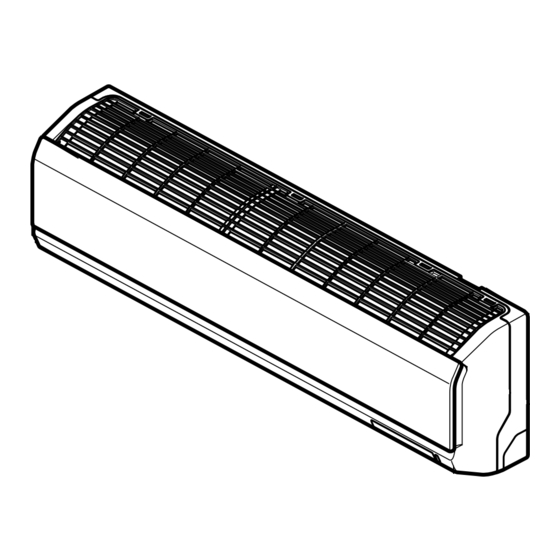
Room Air Conditioner
SERVICE MANUAL
MODELS: LSN090CE
LSN120CE
LSN180CE
LSN240CE
LSN090HE
LSN120HE
LSN180HE
LSN240HE
LSU090CE
LSU120CE
LSU180CE
LSU240CE
LSU090HE
LSU120HE
LSU180HE
LSU240HE
CAUTION
• BEFORE SERVICING THE UNIT, READ THE SAFETY
PRECAUTIONS IN THIS MANUAL.
• ONLY FOR AUTHORIZED SERVICE PERSONNEL.
website http://www.lgservice.com
LG
Advertisement
Table of Contents


Need help?
Do you have a question about the LSN090CE and is the answer not in the manual?
Questions and answers