Table of Contents
Advertisement
Quick Links
Advertisement
Chapters
Table of Contents

Related Manuals for Moso ST5KTL


Summary of Contents for Moso ST5KTL
- Page 1 光伏并网逆变器 用户手册 ST5KTL / ST6KTL / ST7KTL / ST8KTL 版本号 V2.0(中)...
- Page 2 版权声明 本手册的版权属于茂硕电源科技股份有限公司。任何单位或者个 人不允许复制或部分复制(包括电子版本等等)本手册的内容,且不允许 以任何形式或手段转制和分发。茂硕电源保留所有权利,且拥有最终 的解释权。 所有相关信息有可能会被修改,但不会另行通知, 敬请谅解。...
-
Page 3: Table Of Contents
目录 录 1 关 关于本手册 ..1 ...................... 1 适用性 ..1 ...................... 1 使用对象 ...................... 1 1 安全 ..1 ... - Page 4 3 连接 PV 组 组件 .................... 2 3 3 8.3.1 直流接 接线注意事项 项 ..... 3 .............. 2 3 8.3.2 直流连 连接器组装 ..4 .................. 2 4 8.3.3 连接 P PV 组件 ...
- Page 5 变 器的 的产品信息、 安装、操作 作及维护指 引。请在安 安装前仔细阅 阅读本手册, 并将 将手册妥善保 保存方便日后 后查阅。 1 适用性 性 本手 手册适用以下 下逆变器型号 号: ST5KTL 、 ST7KTL、 L、 ST6KTL ST8KTL。 2 使用对 对象 本手册适用 用于安装、操 操作和维护逆 逆变器的专业 业技术人员 ,以及需要 要 查看 看逆变器信息 息的终端用户 户。 3 安全...
-
Page 6: 安全说 说明
1.3 .2 安全说 说明 电 电击危险! 所有涉及 到本逆变器的 的安装、 调试 试、 维修等工作 作都需要经过 过 培训且合格 格的专业人员 员(后简称“ “专业人员” ) 来完成。 本逆变器禁 禁止儿童、 行 行为能力有限或 或者有精神障 障碍的人操作 作 使用, 缺乏 乏相关操作经 经验和常识的人 人应当在专业 业人员指导的 的 情况下使用 用和操作本逆 逆变器。 有可能接 触到本逆变器... - Page 7 警 警告! • 请用户确保 D DC 输入端的 的光伏组件开路 路电压不能超 超过机器的最 最 大 大直流输入电压 压; • DC 端过压有 有可能对本逆 逆变器造成永久 久性的伤害以 以及其他不能 能 DC 端过压造 预 预见的损失,D 造成的逆变器问 问题不属于本 本逆变器的质 质 保 保范围! 警 警告! 经培训的维修 修人员对本逆 逆变器进行任 任何的维护或清 清洁工作前, • 务...
- Page 8 高 高温危险! 逆变器表面 面温度较高, 为了避免灼 伤的风险,当 当逆变器运行 行 时,请不要 要接触逆变器 器表面。另外 ,请将逆变器 器安装在儿童 童 不能触碰 的地方。 电 电击危险! 存在电击危 危险! 禁止拆 拆卸外壳! 请具 具备服务资质 质的电工进行 行 检修。 电 电击危险! 光伏组件暴 暴露在阳光下 下时,其输出 出端会产生直 流电压。 要 要求用户安装前 前阅读用户手 手册、...
- Page 9 • 打 打印标签上的 的符号标志 符号 号标志 解释 E 认证标识。 符合 CE 认证 本逆变器 证相关的各项 项要求和标准 。 UV 认证标识 识。 符合 TUV 认 本逆变器 认证相关的各项 项要求和标准 准。 QC 认证标识 识。 符合 CQC 认 本逆变器 认证相关的各 项要求和标准 准。...
-
Page 10: 电气框图
简介 1 示意图 图 本图 图只做参考, 以实际收到 到的产品实物 为准。 图 2 外形 形图 2 电气框 框图 • 电 电气框图 图 3 电气 气框图... - Page 11 3 产品描 描述 图 4 序 序号 名称 描述 逆变器 器安装的有一 一个直流开关 , 用户可以通 通 直流开关 过直流 流开关安全的 的断开光伏组 组件与逆变器 器 之间的 的连接。 逆变器 器具有两路独 独立的 MPPT, PV1 和 PV2, 直流端子 每路 M MPPT 含有两组 组直流输入端 端子。 WiFi/GPRS 连接 W WiFi 模块或者...
- Page 12 图 5: ST5K KTL/ST6KT TL/ST7KTL/ /ST8KTL 图 · 重 重量 表格 型 型号 ST5KTL ST6KTL 7KTL ST8KTL 24kg 24kg 24kg 重 重量...
- Page 13 3 包 包装清单 单 表格 2 项目 名称 数量 量 光 光伏逆变器 挂板 膨 膨胀螺钉螺母 母 直 直流连接器 膨胀螺钉 S485 连接器 器 用户手册 按以下物品 品出运:...
- Page 14 逆变 器 用户手册 册 图 6...
-
Page 15: 输入(直流
( (Vdc) 22/22 2/22 22/22 22/22 最大 大输入电流 PT 路数 / 单个 M MPPT 串数 最大 大短路电流 (A) 2 输出 (交流) 表格 Model ST5KTL ST6K T7KTL ST8KTL 最大交 交流输出功 率 率(KW) 最大交 交流视在功 率 率(kVA) 额定 定交流电压 3/N/PE/230 0/400 (Vac) -
Page 16: 护等级
电 电网频率 50/60 0/60 50/60 50/60 (Hz) 最大 大输出电流 功率因 因素(cosФ) 8leading-0.8 8lagging 调节 电流 流畸变率 <3% < <3% <3% 3 逆变效 效率、安 安全及防护 护等级 表格 Model ST5KT 6KTL ST7KTL ST8KT 98.5% 8.5% 98.6% 98.6% 最 最大效率 98.1% 8.1% 98.3% 98.3% 欧... - Page 17 4 一般数 数据 表格 Model ST5KT 6KTL ST7KTL ST8KT 尺寸 430/550/ (W/H H/D) [mm] 24kg 重 重量[kg] 工作 作温度范围 -25℃~+ 60℃(>45 5℃降额输出 出) [°C] 防 防护等级 IP65 C60529) (IE 保 保护等级 气 气候类别 4K4H (IEC 6 60721-3-4) 夜间 间功率损耗 <1W 散...
- Page 18 功能 逆变 变器的功能可 可归纳如下: 【逆 逆变功能】 逆变 变器将直流转 转换为与所安 安装地区电网 要求一致的交 交流电, 并将 将其馈入电网 网。 【数 数据存储】 逆变 变器存储了运 运行信息、故 故障记录等系 统信息。 【参 参数配置】 逆变 变器提供了多 多种参数配置 置,以符合各 种需求或将其 其运行性能调 调整至最佳。 。 【通 通讯接口】 可连 连接 WiFi 通讯 讯模块或 RS S456/GPRS 数...
- Page 19 工作模 模式 图 7 注 注意! 温 温度保护下, 逆变器功率 率下降属正常 常现象; 但 如果此现象 象 经 经常产生,请 请检查逆变器 器的散热器 ‘是否积累灰 灰尘’和风 风 扇 ‘是否堵转’ ,或考虑将 将逆变器置于 于通风较好处 处;若此输 出功率下降 降 是由 由电气问题造 造成,请联系 系专业人员协 协助。...
- Page 20 安装 1 安全指 指引 危 危险! 错 错误的安装, 易引起火灾 灾或爆炸而危 危及生命。 · 请勿将逆变 变器安装在易 易燃易爆的物 物品上; · 安装逆变器 器之前,务必 必确保逆变器 器无任何电气 气连接。 小 小心! 不 不当的搬运操 操作可能导致 致人员受伤。 。 · 在移动和运 运输逆变器时 时注意逆变器 器的重量; · 选择一个牢 牢固的安装面 面,最好是牢 牢固的石墙或 或木墙; ·...
- Page 21 2 选择安 安装地点 点 · 安装方法及 及安装位置必 必须与本逆变 变器重量和尺 尺寸相适应 。请选择可 可 承受 受本逆变器的 的墙面或固体 体垂直面。 · 使 使用的环境 境温度不能超 超出本机器工 工作温度范 围(-25°C 至+60°C; 45°C C 至+60°C 降额使用) ; ; 过 2000 米, · 安 安装位置海 海拔不要超过 否则逆变器 器会降额输出 出; ·...
- Page 22 3 安装前 前准备 请准 准备以下安装 装工具: 图 9 安装 装工具 4 安装板 板 本逆变器需 需适当的散热 热空间。 请安 安装在较为开 开阔且通风 良好的地方 方: 图 10 散热 热空间 预定好 4 个 用直径 8mm 用安装板预 钻孔位置, 在预定位置 置处钻孔(用...
- Page 23 钻头、钻 40- -45mm 的深 的钻 深度) ,接着塞 塞进膨胀螺 栓,请保留 膨胀螺栓的 的 牙端 8-10mm m 在外。如下 螺牙 下图: 图 11 墙面 面钻孔 然后 后按以下图示 示安装板、并 并旋紧膨胀螺 螺栓螺母。 图 12 安装 装板安装...
-
Page 24: 器机身
5 安装逆 逆变器机 机身 将逆 逆变器机身扣 扣挂在已安装 装好的安装板 板上: 图 13 安装逆 图 逆变器机身 逆变 变器两侧必须 须正确地卡在 在卡槽上,如 如下图: 图 14 4 逆变器两侧 侧卡在卡槽上 上... - Page 25 6 检查安 安装状态 态 · 检 检查后上方 方卡扣是否扣 扣紧在安装板 板上; · 试 试着将逆变 变器机身向左 左右晃动,以 以确认逆变器 器是否固定牢 牢靠; 请确保 LCD D 显示屏可清 · 请 清楚被看到 ; · 防止逆变器 器在工作的时 时候震动,请 请选择牢固的 的墙面或其他 他固体面。...
-
Page 26: 接线区域
电气连 连接 1 安全 注 注意! · 机器内部有 有静电敏感性 性器件,请避 避免无保护 的方式接触 触 机器 器内部; ·请 请在接触内部 部任何器件前 前确保自身 的可靠接地 地。 2 接线区 区域 图 15 接线 线区域 7 接线区域 表 域信息列表 项目 目 描 描述 直 直流开关 光 光伏组件连接 接器... - Page 27 3 连接 P PV 组件 .1 直流接 接线注意事 事项 MPPT:PV V1 和 PV2, 每路 MPP PT 有两路光 逆变器有两 两路独立的 光 伏组 组串输入,共 共四路光伏组 组串输入端子 子。 · 每 每路 MPPT T 对其接入组 组件有如下要 要求: --同样的型 型号 --每串同样 样的数量 --同样的排 排列 --同样的倾 倾角...
- Page 28 · 逆 逆变器出厂 厂自带一个直 直流开关,安 安装时推荐外 外接一个直流 流断路器。 在逆 逆变器安装时 时,如下条 件不能被超 超越: 最大直流输 输入电压 每 路MPP最大 大直流输入电 电流 1,100 V (DC) 22 A A (DC) 直流 流输入不能混 混接 V1’,而负极 PV2’,这 ·例 例如,一串组 组件的正极连 连接到‘PV 极连接到‘ 这 种情 情况就叫做混 混接。 到一个...
- Page 29 图 17 连接 接顺序: 断开直流开 开关,确保它 它不会在不经 经意的情况下 下被重新打开 开 剥开7毫米 电缆: 图 18 将剥开的电 电缆插入金属 属芯, 并确保 保所有的导体 体铜线被插入 入连接孔内。 。 使用压线钳 钳,压接接触 触孔;将接触 触孔和线缆放 放进相应的 压接口,压 压 紧连接处。 图 19 将组装的连 连接电线插入 入公连接器和 和母连接器背 背部,如组 装的电线安 安 装正确,应 应该能听到或...
- Page 30 图 20 用2.6~2.9 9NM的转矩拧 拧紧胶套。 图 2 当拧紧后, 将光伏组件 件的正负极连 连接头连接至 至逆变器的 对应接口并 并 插紧,直到 到听到或感到 到“卡塔”的 的一声。 图 图 22 如果要分开 开连接器,请 请使用专门的 的扳手工具分 分开他们。 图 图 23...
- Page 31 8.3 .3 连接 P PV 组件 危 危险! 逆 逆变器内部高 高压会危及生 生命。 在连接 PV V 组件之前, · 请确保交流 流侧三相断 路器已经断 断 开 开,并且不会 会被合上。 注 注意! 过 过电压会损坏 坏万用表等测 测试工具 00Vdc的测量 • 请用最大耐 耐压高于110 量工具(如 万用表)去 去 测 测试逆变器的 的输入电压。 。...
- Page 32 FF’ 图24 直 直流断路开关 关处于‘OF 连接 接步骤: .检查光伏组 · 组件连接器极 极性是否正确 确并用万用表 表确认组件 开路电压低 低 于逆 逆变器最大允 允许输入电压 压; 图25 5 测量PV组 件开路电压 压 · .检 .3.2 注意’ ; 检查PV组件 件是否存在直 直流接地, 具 具体描述请参 参见章节 ‘1. .确认PV组件 · 件极性与逆变 变器连接器 匹配,并将...
-
Page 33: 连接电 电网条件
4 连接交 交流电网 网 .1 连接电 电网条件 在 在将逆变器接 接入电网前, 请先与当地 地电网运营商 商接洽好。 线材 材要求: 表 8 8 线材和微断 断路器规格 型 型号 ST5KTL ST6KTL 7KTL ST8KTL 线 线缆 ≥4mm ≥4mm ≥ ≥6mm (铜) 微 微断路 (推荐) 器( .请使用多芯 缆总外径 14 -25mm;... -
Page 34: 电网连 连接步骤
装位 位置应易于操 操作。 危险! 可危及生命 命的火灾. • 当多个逆 逆变器同时 接在同一个 个断路器上, 断路器的保 保 护功 功能将不能得 得到保障,且 且易引起线缆 缆起火或者 逆变器损坏 坏; • 请 请勿将多个逆 逆变器连接到 到同一断路器 器上; • 请 请根据逆变器 器输出最大电 电流来选择断 断路器,一 般选用额定 定电流为 1.5 倍逆 逆变器最大输 输出电流的断 断路器为宜 。 危险!... - Page 35 表格 4 输出 ‘表 ’ ) ; • 断 断开电网侧三 三相微型断路 路器并确认其 其不会被合 合上; 参见图 30) • 卸 卸掉交流输出 出端防护罩四 四个螺钉(参 ; 图 图 27 拆除交 交流防护盖 图 31) ; • 松 松开交流接线 线端子上的螺 螺钉(参见 图 2 28 松开锁线 线螺钉 图...
- Page 36 图 30 锁紧五 五 芯电缆...
-
Page 37: Led1
操作 1 LED 显 显示灯 个 LED 指示 如下 下图所示,面 面板上有三个 示灯: 图 31 面板 板显示 1.1 LED1- -绿 表 9 无 无直流输入 闪烁 待 待机状态 MPPT 工作中 中... -
Page 38: Led2
1.2 LED2- -绿 表 10 逆变 变器不工作 闪烁 逆变 变器自检中 逆变器 器并网工作中 中 1.3 LED3- -红 表 1 没有 有故障发生 发 发生故障 2 显示器 器 LCD 显示器 器监视逆变 器的状态和 和收集统计数 数据, 以评估 系统的性能 能。 过按键控制 L LCD 进而控 本机器设计 计了六个按键 键,... - Page 39 图 3 33 LCD 界面 面简要描述 2.1 系统 页面 系 系统 2013 -02-20 18: 18:18 Today 功率 88.44 今天 总量 6688.8 20 h 状 状态: 等待 事 事件: 警告 按左右 键或敲击 击面板进 进行换页 。 图 34 功率:当前 前并网功率; 今天: 截止 止到当前时刻...
- Page 40 2.2 信息 页面 信息 2013-0 02-20 18:18 状态: 等待 当前事 事件: F13] 通信 信失败 1.[F 按上下 下键查看更 更多。 图 35 系统状态是 是通过消息页 页面来显示 的; 第一行显 显示逆变器 的操作模式 式: 等待 待模式,自检 检模式,并网 网模式,故障 障模式。 下面显示详 详细的当前发 发生的事件 。 开始是 LCD 从第二行开 显示警告与...
- Page 41 PV1 绝缘 缘故障 PV2 绝缘 缘故障 绝缘电源 故障 母线欠 压 母线不平 平衡 母线过 压 输出过 流 Boost 过 过流 输 输出直流分 量过高 剩余电流 异常 接线错 误 相序反 反 内部 AD 故 故障 继电器短 短路 继电器开 开路 监 监控 ARM 通 通讯异常...
-
Page 42: Rs4
通讯设 设置 .1 通讯 讯端口类型 型 供标准的 RS S485 通讯端 也可选 WiFi/G GPRS 通讯 本产品提供 端口, 同时也 讯 方式 式。各类系统 统运行数据, ,如输出电 压、电流、 频率、故障 障信息等等, 都可 可以通过通讯 讯端口传输至 至相应的监控 控设备。 .2 通讯 讯方式 2.1 RS4 了标准的 R S485 接口, 光伏并网逆 逆变器提供了... - Page 43 36 RS485 5 通讯端口 图 图 37 8 线 线 RJ45 表 13 8 线 线 RJ45 8 线 线 RJ45 线 线编号. 功能 颜色 色 橙 白 橙 橙 绿 白 蓝 蓝 蓝 白 绿 绿 棕 白 棕...
-
Page 44: Wif I
转换 换线缆,如下 下图所示: 图 38 茂 茂硕电源 Web bbox 监控示 意图 · 将 将上述系统 统通过 RS48 5/USB 转换 换接头接到 P PC 上 图 图39 RS485装 装换连接PC 2.2 WiF i (可选) · WiFi 通讯 供可选的 W WiFi 的通讯方 逆变器提供 方式,如果你 你向茂硕电 源公司订购... - Page 45 器上 上,请参见下 下图: 图40 内置 置Wifi ifi的使用方 方法请参看W Wifi模块的使 使用手册! · Wifi 与逆变 变器连接 图41 Wifi监 监控模式...
- Page 46 故障检 检测 在大多数情 情况下,本逆 逆变器是不需 需要单独进 行维护的。 但是,如果 果 机器 器不能够完美 美地正常工作 作, 请遵照以 以下指引做出 出充分的判 断后再联系 系 您所 所在的地区经 经销商或者授 授权的维修 中心。如果有 有任何故障 障出现,本机 机 的 LED3 指示 , LCD 界面也 器操 操作面板上的 示灯会变红 也会有显示 相应的信息 息, 请参 参考下表中可 可能出现的问...
- Page 47 的 的最大的直流 流输入电压 ,请向我们 们 寻 寻求帮助。 · 断开逆变 变器直流开关 关, 然后再重 重 新 新合上。 输出直 流分量过大 大 · 检查输出 出线是否有误 误接。 · 如无法解决 决, 请向我们 们寻求帮助。 · 断开逆变 变器直流开关 关, 然后再重 重 新 新合上。 继电 电器故障 · 如无法回 复到正常状 状态,...
- Page 48 逆变器 器报废 .1 拆卸 · 将逆变 变器的直流输 输入端和交流 流输出端均断 断开; · 将逆变 变器所有的连 连接缆线拆除 除; · 将逆变 变器从安装板 板上拆除。 .2 包装 装 尽可能用原 原始包装存储 储逆变器,如 如果没有原始 始包装,请 使用相似的 的 包装 装并满足以下 下条件: 能力超过 24 公 · 承重能 公斤; · 可以完 完全合上的。...
- Page 49 质保期 期 产品 品自购买之日 日起提供五年 年质保服务。 。 · 保 保修产品 保修 修产品仅限于 于以下产品: ST5KTL/ST T6KTL /ST7 7KTL/ST8K · 产 产品质保( 有限责任) (适用于正常 常应用、安 安装、使用及 及维护的机器 器)。 茂硕电源承 承诺上述型 号的产品在 在质保期内没 没有任何影响 响使用的缺 缺 陷, 且承诺在质 质保期内为上 上述型号的产 产品提供相应 应的质保服 服务,质保期...
- Page 50 茂硕电源科技股份有限公司 地址: 中国广东省深圳市南山区西丽镇松白路 1061 号茂硕科技园 营销服务中心 电话: 400-756-5188 传真: (86-755) 2765-7908 网站: www.mosopower.com 邮箱: sales.solar@mosopower.com 售后服务中心 电话: 400-756-5188 传真: (86-755) 2765-7908 邮箱: service.solar@mosopower.com...
- Page 51 Solar On-Grid Inverter ST5KTL/ST6KTL/ST7KTL/ST8KTL User Manual Version 2.0 (EN)
- Page 52 All rights to the content of this manual are owned by MOSO Power Supply Technology Co., Ltd (hereinafter “MOSO”). No part of this document can be modified, distributed, reproduced or published in any form or by any means without prior written permission from MOSO.
- Page 53 Table of Contents 1 ABOUT THIS MANUAL .................. 3 ...................... 3 PPLICABILITY ...................... 3 ARGET ROUP ......................... 3 AFETY 1.3.1 Application .................... 3 1.3.2 Safety Instructions.................. 4 1.3.3 Safety Symbols ................... 5 2 INTRODUCTION .................... 8 ...................... 8 ...
- Page 54 .............. 2 6 VERVIEW OF THE ONNECTION (DC) .............. 2 7 ONNECTION OF THE RRAY 8.3.1 Conditions for DC Connection .............. 2 7 8.3.2 Assembling the DC Connectors .............. 2 8 8.3.3 Connecting the PV Array (DC) .............. 3 0 (AC) ................... 3 3 ONNECTION TO RID 8.4.1 Conditions for AC Connection .............. 3 3 8.4.2 AC Connection Procedure ................ ...
-
Page 55: 1 About This Manual
Inverter owners who will have the ability to interact with the inverter. 1.3 Safety 1.3.1 Application The ST5KTL/ST6KTL/ST7KTL/ST8KTL is a series of three phase on-grid inverter, which main function is to convert the DC current from PV strings into AC current and feed it into grid. -
Page 56: Safety Instructions
A.PV Strings B. ST5-8KTL C. AC Distribution Unit D. Grid Figure 1 Principle of a PV Plant with ST series inverter 1.3.2 Safety Instructions Safety symbols used in this manual, which highlight potential safety risks and important safety information, are listed as follows: CAUTION: Risk of electric shock. -
Page 57: Safety Symbols
Warning! Please do not connect PV array positive or negative to ground, it could cause serious damage to the inverter. PV module used with inverter must have an IEC 61730 Class A rating. Warning! • Ensure that input DC voltage is less than max. DC voltage. - Page 58 Symbol Description Danger of high voltage! R esidual voltage will vanish in 5 minutes after the inverter disconnected. Open the front cover of the inverter at least 5 minutes after disconnecting. Beware of hot surface! The inverter can get hot during operation. Avoid ...
- Page 59 You can operate the interface by tapping on it. • Tapping once: The background illumination switches • Tapping again: Updating information. You can operate the interface by pressing buttons. For more information on operating the buttons, refer to Section 7.2 ‘LCD display’. Recovery and recycling.
-
Page 60: 2 Introduction
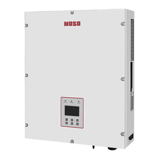
2 Introduction 2.1 Overview The image shown here is for reference only. The actual product you receive may differ. Figure 2 Stereogram 2.2 Electrical Block Diagram · Electrical block diagram Figure 3 Electrical block diagram... -
Page 61: Product Instruction
2.3 Product Instruction Figure 4 Name Description The DC switch can disconnect DC Switch strings inverter safely ST Series Inverters have two independent MPP trackers PV1 and PV Terminals PV2. Per tracker has input terminals. Terminals connect the WiFi Terminal WiFi module or GPRS module. -
Page 62: Dimension And Weight
internal. AC Terminals AC output The display shows the status information (e.g. working status, LCD Display power, input voltage) as well as errors and disturbances. 2.4 Dimension and Weight · Dimension... - Page 63 Figure 5 ST5KTL/ ST6KTL/ ST7KTL/ ST8KTL · Weight Table 1 Model ST5KTL ST6KTL ST7KTL ST8KTL Weight 24kg 24kg 24kg 24kg...
- Page 64 ·List Table 2 3 Packaging List Item Name Quantity Solar Inverter Mounting Frame expansion bolt PV connector plug bolt plug bolt RS485 connector User Manual The ST series inverter is shipped with the following items:...
- Page 65 逆 变 器 用 户 手 册 Figure · Identifying g the Invert u can identif fy the invert ter by the n ameplate. T The namep plate is loca ated on the right-hand side of the housing. e inverter ty pe (type/mo odel), seria l number (s...
-
Page 66: 4 Technical Data
4 Technical Data 4.1 Input(DC) Table 3 Inverter Model ST5KTL ST6KTL ST7KTL ST8KTL Input(DC) Max DC power 7500 W 9000 W 10500 W 12000 W Max DC voltage 1100 V Start voltage 160 V MPPT voltage range 200-950 V Rated input voltage... -
Page 67: Output
4.2 Output(AC) Table 4 Inverter Model ST5KTL ST6KTL ST7KTL ST8KTL Output(AC) Rated output power 5 kW 6 kW 7 kW 8 kW Rated output voltage 3/N/PE~230V/400V AC voltage range 310~480 V(Conform to local standards) Rated AC grid frequency 50Hz/60Hz Max output current Adjustable power factor 0.8leading-0.8lagging... -
Page 68: General Data
>99.9% >99.9% >99.9% >99.9% Protection DC Switch DC reverse polarity protection DC surge protection Insulation monitoring AC overcurrent protection AC surge protection Anti-islanding protection Residual current monitoring 4.4 General Data Table 6 Inverter Model ST5KTL ST6KTL ST7KTL ST8KTL General data... -
Page 69: 5 Function Description
Operating temperature -25℃ ~ +60℃ range Relative operating 0% RH ~ 100% RH humidity Operating altitude 0~4,000 m (Derating above 2000 m) Cooling Fans Display LED + LCD Communication RS485/WiFi(opt.)/GPRS(opt.) Dimension(W*H*D) 430/550/180 mm Weight(incl. mounting 24 kg bracket) Degree of protection IP65 Warranty 5 years/10 years(opt.)/15 years(opt.) -
Page 70: Operation Mode
Inverter logs essential data including running information and error records. 【Parameter configuration】 Inverter provides various parameter configurations for optimal operation. 【Communication interface】 You can choose the RS485 terminal for connecting a communication module to the PV system, such as Wi-Fi module. 【Protective function】... -
Page 71: 7 Installation
Figure 7 NOTICE! The inverter output power decrease is usual in the condition of thermal protection, but if it occurs frequently, you need to check the heat sink or consider putting the inverter in the place where have better air flow, and if output power decreases caused by electrical problem, please ask for professional supports. - Page 72 • Some parts of the inverter will be hot during operation. ·Open the package Check the inverter and accessories according to the pack list. If the inverter is damaged or any accessory missing, please contact the local distributor. 7.2 Installation site selection The following must be considered when selecting the location for an inverter: ...
- Page 73 Figure 8 Installation • Mount the inverter at eye level. Given the weight of the device, this will facilitate disassembly if service work is necessary. • The ambient temperature should be lower than 40°C to achieve optimal performance. • Do not expose the inverter to direct sunlight as this can cause excessive heating and thus power reduction.
-
Page 74: Preparation
Figure 9 • If multiple inverters are mounted in areas with high ambient temperatures, increase the clearances between the inverters and ensure an adequate fresh-air supply. This will prevent a reduction in inverter power as a result of excessively high temperatures (details on temperature derating can be found in the Technical Information). -
Page 75: Fixed The Mounting On The Wall
7.4 Fixed the Mounting on the Wall Space for heat dissipation should be reserved while installing the inverter. Install the inverter with good ventilation condition. Figure 11 Align the wall mounting bracket horizontally on the wall with the arrow upwards. Mark the position of the drill holes. Drill the marked holes. -
Page 76: Fixed The Inverter On The Wall
Figure 12 7.5 Fixed the Inverter on the Wall Mount the inverter to the bracket. Figure 13... -
Page 77: Check Inverter Installation Status
Fasten the inverter into the T slot. Figure 14 7.6 Check Inverter Installation Status • Check the upper straps of Inverter to ensure it fixed on to the bracket. • Check the secure mounting of the PV-Inverter by trying to raise it from the bottom. -
Page 78: 8 Electrical Connection
8 Electrical Connection 8.1 Safety NOTICE! Electrostatic discharge can damage the inverter. • Internal components of the inverter can be irreparably damaged by electrostatic discharge. • Earth yourself before touching any components. 8.2 Overview of the Connection Area Figure 15 Table 7 Object Description... -
Page 79: Connection Of The Pv Array
8.3 Connection of the PV Array (DC) 8.3.1 Conditions for DC Connection The inverter has two PV input terminals, "PV1" and "PV2", each of them connects two strings. Up to four strings can be connected in total. • Requirements for the PV strings: –... - Page 80 he open circ cuit voltage of the PV s strings cann not exceed e maximum m input volta age of the in nverter. Maximum input Maxim mum input current pe er MPP voltag trac cker 1,100 V ( (DC) 22 A (DC) o mixed PV V connectio...
- Page 81 Figure 17 Connection steps: 1. Turn of the DC switch and make sure it will not be turned on accidentally. 2. Strip the insulation layer and protective sleeve of the cable, and leave the bare cooper conductor in 7mm. Fugure 18 3.
-
Page 82: Connecting The Pv Array
Fugure 20 6. Screw the end cap with a torque of 2.6~2.9NM. Fugure 21 7. Connect the connectors with the inverter terminals when there is a “click” sound. Fugure 22 8. Using a wrench to take apart the connection when it is necessary. - Page 83 NOTICE Over vo ltages wou uld damage e the multi meter. DC input vo oltage rang ge of the mu ultimeter shou uld be over 1,000 Vdc. Turn off D DC input by y turning the e DC switch h to OFF (see fig 2 25).
- Page 84 Figur re 25 Check and d make sure e the PV str rings are no ot grounded d. Refer to Section 1.3 3.3 ‘note’. Check the polarity of the PV mod dule output matches th he polarity of the inve erter connec ctor.
-
Page 85: Connection To Grid
The PV co onnectors a are IP68, bu ut can’t be e exposed to water for a a long time. 4 Conne ection t o Grid ( (AC) 4.1 Cond ditions fo or AC Co onnectio u must comp ply with the e connection n requireme ents of your... - Page 86 be equipped with a three phase 4P micro circuit breaker (hereinafter MCB). A MCB can disconnect Line L1/L2/L2/N of AC output with the live wire/zero wire of grid. Install the MCB where is easy to access to and operate. DANGER! Danger to life due to fire.
-
Page 87: Ac Connection Procedure
• A screw fuse can only use as circuit protection instead of a load disconnecting device. • Please use a isolating switch or a MCB as load disconnecting device. 8.4.2 AC Connection Procedure Check if the grid voltage and frequency accordant with the inverter setting (refer to Section 4.2"Output"... - Page 88 Figure 29 AC terminals Connect L1, L2, L3, N and the protective conductor (PE) to the AC terminal in accordance with the labeling (see fig 30). – To do this, the PE insulated wire must be 5 mm longer than the L and N insulated conductors.
-
Page 89: Operation
Figure 31 DANGER! Danger to life due to high voltages in the inverter. • Do not switch on the miniature circuit-breaker until the PV array has been connected and the inverter is securely closed. 9. Operation 9.1 LED Display There are three LED indicators on the panel: Six buttons... -
Page 90: Dc/Dc Status Led 1 (Green)
Figure 32 9.1.1 DC/DC status LED 1 (Green) Table 9 The DC/DC circuit is off. Blinking The DC/DC circuit starts. The DC/DC circuit is working normally... -
Page 91: Dc/Ac Status Led 2(Green)
9.1.2 DC/AC status LED 2(Green) Table 10 The DC/AC circuit is off. Blinking The DC/AC circuit starts. The DC/AC circuit is working normally. 9.1.3 Fault LED 3 (Red) Table11 No error occurs The inverter is in fault status Normally, after starting up, DC/DC LED and DC/AC LED will light which indicates that the inverter is feeding electricity to the grid. -
Page 92: System Page
below, the LCD will show next page by a single tap or press the left or right button. Figure 34 Summary diagram 9.2.1 System Page Figure 35 Power: the present power feeding into the grid; Today: Energy exports to the grid in the present day, and updates the data every 10 minutes;... -
Page 93: Message Page
Testing Mode, On-grid Mode, and Fault Mode; Event: If the inverter reports warnings, the display will show up Warning, and the report can be found in next page. Warning will be eliminated and the display in this page will be blank. 9.2.2 Message Page Figure 36 The system status is shown on the page of MESSAGE. - Page 94 RC chip Fault Aux Power Fault Over Temp Fault Pv1 Iso Fault Pv2 Iso Fault PLL Fault Viso Power Fault Bus Volt Low Fault Bus Un Balance Bus Ovp Fault Ocp Ac Ocp Boost IAC_ RMS_ Unbalance DCI Gird over limit GFCI Fault Pv Config Set Wrong Unrecover Phase Sequence Fault...
-
Page 95: Communication Terminal Types
10 Setting up Communication 10.1 Communication Terminal Types MOSO ST6/7/8KTL can use RS485 and WiFi for communication. 10.2 Communication 10.2.1 RS485 · RS485 Communication (Applied to one inverter or multiple inverters) In general, RS485 can be used for the communication with up to 32 units. - Page 96 Figure 37 Figure 37 Communication Interface of ST Series Inverters Figure 38 8-line RJ45 Table13 8-line RJ45 8-line RJ45 Wire Function Wire Color Orange white Orange Green white Blue Blue white Green...
- Page 97 Brown w white Brow · C Connectio n method b between R RS485 and W Webbox mmunicatio n cables a are used f for connec ction amon g the ST inve erters. A cro ossover cab ble is used to connect t the inverte er with the bbox.
-
Page 98: 11 Troubleshooting
Figure .2.2 Buil ld-in WiF Fi (optio onal) e WiFi comm munication function is only applica able if the in nverter a WiFi mo dule. The W WiFi module e is built-in a and installe ed in the inve erter before shipment f from the ma anufacturer... - Page 99 corresponding solutions. Table 14 Troubleshooting list Faults Diagnosis and Solutions -Waiting for one minute until the grid goes back to normal working status. - Check if the grid voltage and frequency complies with the standards setting. -Call the local service office. Grid Failure -Off to grid.
-
Page 100: Dismantling
—Check if the size and length of all cables is proper. —Check if the connection of output terminals and wiring is proper. —Check if the configuration setting is proper. —Check if the connection between the display board and the communication cable is proper. 12 Decommissioning 12.1 Dismantling ●... - Page 101 13 Warranty MOSO offers 5-year warranty starting from the inverters delivering from the manufacturer’s warehouse. Warranty certificate represents a five year warranty service for mentioned products since the date of purchase. Warranted Products This warranty is applicable solely to the following products:...
Need help?
Do you have a question about the ST5KTL and is the answer not in the manual?
Questions and answers