Table of Contents
Advertisement
Quick Links
Advertisement
Table of Contents

Subscribe to Our Youtube Channel
Related Manuals for KBR multisys D2-ESET/MSMT-4


Summary of Contents for KBR multisys D2-ESET/MSMT-4
- Page 1 User Manual Technical Parameters Interfaces for KBR eBus, Modbus and Modulbus multisys D2-ESET/MSMT-4 multisys D2-BSET-4 You will find the relevant instructions for KBR System English devices in our Download Center. https://www.kbr.de/de/dienstleistungen/ download-center...
- Page 2 We would be very grateful if you would notify us of any errors or unclear descrip- tions you may notice. KBR Kompensationsanlagenbau GmbH does not accept any liability for any loss or damage resulting from printing errors in or changes to this manual.
-
Page 3: Table Of Contents
Hardware Configuration ....................... 6 RS485 Interface and LAN ......................6 LAN and KBR Module Bus Interfaces (multisys D2-BSET-4) ..........7 Software configuration ......................... 8 Assigning an IP Address to a Device of which the Address is Not in the Address Range of the Network .........................10... -
Page 4: Multisys D2-Eset/Msmt-4
- Modbus On the Energy Bus side it acts as server and on the Ethernet side it acts as client. The two interfaces (RS-485 on the KBR eBus side, and Ethernet on the network side) are galvanically separated. The multisys D2-BSET-4 connects the KBR module bus to your computer through an Ethernet connection. -
Page 5: Connection Diagram
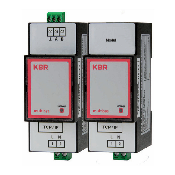
Connection diagram Both variations are described below. Connection diagram R 12 zu weiterenTeilnehmern Modulbus bzw. Leitungsabschluss / to other bus devices and line termination Modulbus/ Module bus multisys multisys D2-BSET-4 D2-ESET/MSMT-4 V4.00... -
Page 6: Hardware Configuration
Interfaces LAN and KBR eBus RS-485 Hardware Configuration RS485 Interface and LAN The RS-485 interface is set to the KBR eBus parameters 38,400 baud, 8 data bits, parity even, 1 stop bit. If necessary, it can be terminated using four DIP switches. RS485 RS-485 (3-pole multi-pin connector, 3.5 mm) -
Page 7: Lan And Kbr Module Bus Interfaces (Multisys D2-Bset-4)
Interfaces LAN and KBR module bus LAN and KBR Module Bus Interfaces (multisys D2-BSET-4) The Modbus interface is set to the Modbus parameters 38,400 baud, 8 data bits, parity even, 1 stop bit. If necessary, it can be terminated using four DIP switches. -
Page 8: Software Configuration
Software configuration Software configuration The present device is available in a version with Lantronix LAN port (until approx. Dec 2020) or IOT LAN port (from approx. Jan 2021). There are three options for parameterizing the LAN port for these versions: 1. - Page 9 Software configuration NOTE For security reasons, the IP address of the device should be changed immediately, to prevent unauthorized persons from accessing the device from outside. In addition, the device should be password protected (for devices of the multimess series). System Settings Change the device system settings Authentication...
-
Page 10: Assigning An Ip Address To A Device Of Which The Address Is Not In The Address Range Of The Network
Software configuration Assigning an IP Address to a Device of which the Address is Not in the Address Range of the Network In the main window of the IOT Service Tool, open the ‘BroadCast Scan’ window via Setting (C) -> BroadCast. E-port devices that are in the network but do not have a valid network address are listed here. - Page 11 Software configuration After selecting the e-port, click on „Config“ to access the configuration settings. V4.00...
-
Page 12: E-Port Configuration For Ebus Tcp
Software configuration 3.2. E-port Configuration for eBus TCP For eBus TCP, the parameters must be set as shown in the figure below. The network parameters (IP address, mask, gateway, DNS) must be adapted to local circumstances. NOTE - Flow Control: Half Duplex“ controls the changeover of RS-485 components. - The local port must be set to 8000 - Click „Confirm“... - Page 13 Software configuration When „Detail“ is selected, this window appears: NOTE - UART protocol should be set to ‚NONE‘ for eBus-TCP. - Gap Time should be set to 10 (ms) (waiting time after serial reception, until Telex is sent over the network). - Cli Waiting Time should be set to 15 (seconds) max.
-
Page 14: Box-To-Box Operation (Parameters Of The Server)
Software configuration Box-to-Box Operation (parameters of the server): For this, the following settings are important: V4.00... -
Page 15: E-Port Configuration For Modbus Tcp
Software configuration E-port configuration for Modbus TCP For Modbus TCP, the parameters must be set as shown in the figure below. The network parameters (IP address, mask, gateway, DNS) must be adapted to local circumstances. NOTE The UART parameters must be adapted to the local bus parameters. Local port: 502 Several connections to a serial interface, via the TCP, are possible. - Page 16 Software configuration NOTE Modbus ASCII cannot be configured. Several connections to a serial interface, via the TCP, are possible. Replies are only sent to the enquirer. V4.00...
-
Page 17: Lan Ebus Configuration Via Ethernet Interface (Telnet)
LAN eBus configuration LAN eBus configuration via Ethernet interface (Telnet) The Ethernet interface of the multisys LAN eBus can be set up using the Ethernet inter- face via Telnet or the Lantronix tool DeviceInstaller. HINWEIS On delivery, the devices are set to the IP address 192.168.0.1. For this reason, it is recom- mended to check whether the device can be reached using this IP address. - Page 18 LAN eBus configuration Example: Port 00000 Input: arp -s 10.66.22.98 Disconn Mode: 00 00-20-4a-86-c9-91 Flush Mode: 80 Pack Cntrl: Input: telnet 10.66.22.98 1 Expert Response: TCP Keepalive: 45s Establishing connection with CPU performance: Regular 10.66.22.98... Connection to host Monitor Mode @ bootup: enabled could not be established;...
- Page 19 Change Setup: the menu item 0 Server. The settings for 0 Server the serial interface (KBR - energy bus) are 1 Channel 1 made under the menu item 1 Channel 1 E-mail (eBus-Parameter 38400 Baud, 5 Expert 8 Datenbits, Parity even, 1 Stopbit).
-
Page 20: Menu Item 0 Server , Setting Ip Address
7 Factory defaults 8 Exit without save 9 Save and exit Your choice ? 9 Parameters stored ... When entering 9, the changes are saved and accepted. The multisys 3D2-ESET can now be accessed using the KBR Visual Energy computer software. V4.00... -
Page 21: Web Browser Settings
LAN eBus configuration 4.1.4. Web browser settings The settings, which can be adjust by the Web Interface, are documented in the following pictures. Enter the following IP address in your browser page: 192.168.0.1. V4.00... - Page 22 LAN eBus configuration Channel 1 settings / Connection. V4.00...
-
Page 23: Box-To-Box Operation
LAN eBus configuration 4.1.5 Box-to-Box operation In Box-to-Box operation, you can establish a logical permanent network connection between two multisys D2-ESET -4 serial ports. In this operating mode, there is a perma- nent online connection between the two serial terminals connected. Possible additional data traffic or other network protocols do not influence the connection. - Page 24 LAN eBus configuration *** Security Port No (8000) ? SNMP is enabled ConnectMode (C0) ? C3 SNMP Community Name: public Tel- Start Char: (02) ? 02 net Setup is enabled TFTP Down- Send ‚+++‘ in Modem Mode load is enabled Port 77FEh (Y) ? enabled Web Server is...
-
Page 25: Setting The Multisys D2-Eset -4 In Client Operation
LAN eBus configuration 4.1.7 Setting the multisys D2-ESET -4 in client operation NOTE A description of how to set up the multisys D2-ESET -4 in client operation is given in section 3.2. 4.1.8 Web browser settings The settings, which can be adjust by the Web Interface, are documented in the following pictures. -
Page 26: Resetting The Multisys D2-Eset -4
LAN eBus configuration Channel 1 settings / Connection. 4.1.9 Resetting the multisys D2-ESET -4 from server to client operation Example: Server IP address 10.66.22.90 To reset a multisys D2-ESET -4 configured as server to client for „normal“ network operation, you have to change the parameter in the 1 Channel 1 menu as follows: Input: telnet 10.66.22.90 9999 Input: Enter (within 2 seconds) V4.00... - Page 27 LAN eBus configuration Response: 5 Expert MAC address 00204AA63735 6 Security Software version V6.5.0.7 7 Defaults (070919) XPTEXE Press 8 Exit without save Enter for Setup Mode 9 Save and exit Your choice ? 1 *** basic parameters Hardware: Baudrate (38400) ? I/F Mode (7F) Ethernet TPI IP addr 10.66.22.90, no gateway set,netmask 255.255.255.0...
-
Page 28: Einstellungen Mit Webbrowser
LAN eBus configuration 4.1.10 Settings with web browser The settings that can be made using a web browser are documented in the following images. Settings Channel 1 / Serial Settings. V4.00... - Page 29 LAN eBus configuration Settings Channel 1 / Connection. V4.00...
-
Page 30: Technical Data
Connection For proper operation, material use shielded twisted-pair cables only; e.g. I-Y(St)Y 2x2x0.8 BUS connection Pins for Device multisys D2-ESET/MSMT-4 BUS connection Terminal 90 ( ) via RS-485 Terminal 91 (A) Terminal 92 (B) BUS connection 6 pole modular cable, multisys D2-BSET-4 RJ-12 connector: 6P6C max. -
Page 31: Standards And Miscellaneous
Technical data Standards and miscellaneous DIN EN 60721-3-3:1995-09 + DIN EN 60721-3-3/A2:1997-07; Standards 3K5+3Z11; (IEC721-3-3;3K5+3Z11) Operating tem- Ambient K55 (-5°C … +55°C) perature conditions Air humidity 5% …. 95% Storage -25°C … +70°C temperature Operating height 0 … 2,000 m above sea level DIN EN 61010-1:2011-07;... - Page 32 KBR Kompensationsanlagenbau GmbH Am Kiefernschlag 7 T +49 (0) 9122 6373 - 0 www.kbr.de D-91126 Schwabach F +49 (0) 9122 6373 - 83 Germany E info @ kbr.de...
Need help?
Do you have a question about the multisys D2-ESET/MSMT-4 and is the answer not in the manual?
Questions and answers