
Related Manuals for GÜDE Expert Power Control 8221 Series


Summary of Contents for GÜDE Expert Power Control 8221 Series
- Page 1 Manual Expert Power Control 8221 Series Expert Power Control 8226 Series © 2022 GUDE Systems GmbH Manual Ver. 2.9.1 from Firmware Ver. 1.9...
- Page 2 Expert Power Control 8221/8226 © 2022 GUDE Systems GmbH...
-
Page 3: Table Of Contents
Table of contents Device Description Security Advice ......................6 Content of Delivery ......................6 Description ........................6 Installation ........................7 Dual-Circuit Characteristics ................... 8 Overvoltage Protection ....................9 Technical Specifications ....................10 1.7.1 Electrical Measurement ..................11 Sensor ........................... 11 Operating Operating the device directly .................. - Page 4 Table of contents Front Panel ........................53 Specifications Automated Access ....................... 55 Messages ........................55 IP ACL ..........................57 IPv6 ..........................58 Radius ..........................58 SNMP ..........................59 4.6.1 Device MIB 8221 ....................62 4.6.2 Device MIB 8226 ....................64 SSL ..........................
- Page 5 Device Description...
-
Page 6: Device Description Security Advice
Device Description Device Description Security Advice · The device must be installed only by qualified personnel according to the following in- stallation and operating instructions. · The manufacturer does not accept responsibility in case of improper use of the device and particularly any use of equipment that may cause personal injury or material dam- age. -
Page 7: Installation
Device Description · Continuously and resettable energy meters on the mains connections. · Energy Metering and meters for each port of the 12 load outputs and measurement of voltage, current, active power, reactive power, apparent power, frequency , phase angle, power factor per output (8226-1 only). -
Page 8: Dual-Circuit Characteristics
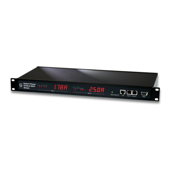
Device Description 5. Status LED 6. Select button 7. Ok button 8. Ethernet connector (RJ45) 9. External sensor connectors (RJ45) 10. RS232 connector 11. Mains supply Bank B (IEC C20, max.16A) 12. 6 x Load outputs Bank B (IEC C13, max. 16A) 13. -
Page 9: Overvoltage Protection
Device Description Twin Port Two ports of different Banks but with the same number can be combined to a "twin port". Then one port always participates in the switching status of the other port. In the screen- shot the ports A1 and B1 are combined, symbolized by the chain link icon. The "Con- nect twin port"... -
Page 10: Technical Specifications
Device Description Technical Specifications Interfaces 1 x Ethernet port (RJ45) 1 x Serial connector (D-SUB, RS232) 2 x Mains supply (IEC C20, max.16 A) 2 x 6 Load outputs (IEC C13, max. 16 2 x RJ45 for external sensor Network connectivity 10/100 MBit/s 10baseT Ethernet Power Supply internal power supply (90-265V AC / -... -
Page 11: Electrical Measurement
Device Description 1.7.1 Electrical Measurement typical fault tolerances for Ta=25°C, I=1Arms...16Arms, Un=90Vrms...265Vrms Electrical Measurement Specification Category Range Unit Resolu- Inaccuracy tion (typical) Voltage 90-265 0.01 < 1% Current 0 - 16 0.001 < 1.5% Frequency 45-65 0.01 < 0.03% Phase -180 - +180 °... - Page 12 Device Description Product Name 7101 7104-1 7105-1 7106-1 Calibrated 7104-2 7105-2 7106-2 Sensor Cable length Connector RJ45 RJ45 RJ45 RJ45 temperature range -20°C to +80°C at -20°C to +80°C at -20°C to +80°C at -20°C to +80°C at ±2°C (maximum) ±2°C (maximum) ±2°C (maximum) ±2°C (maximum)
- Page 13 Device Description A click on the link in the "Name" column opens the display of the Min and Max values. The values in a column can be reset using the "Reset" button. The "Reset" button in the name column deletes all stored Min and Max values. Expert Power Control 8221/8226 ©...
-
Page 14: Operating
Operating... -
Page 15: Operating The Device Directly
Operating Operating Operating the device directly Port Switching The current switching state of the output is indicated by the corresponding plain text dis- plays (port LEDs). If the green "on" LED is lit, the port is switched on, if the red "off" LED is lit, the output port is switched off. - Page 16 Operating The web page provides an overview of the switching state, energy measurement values of the banks "A" and "B", as well as the external sensors, provided that they are connec- ted. When a single port is clicked at the Expert Power Control 8221-1/8226-1, a panel with buttons to control a single port appear: The Port icon is green when the relay is closed, or red in the open state.
-
Page 17: Maintenance
Operating The ports can be switched manually with the "On" and "Off" buttons. If the port is turned on, it can be turned off by pressing the "Reset" button, until after a delay it turns itself on again. The delay time is determined by the parameter Reset Duration, which is de- scribed in the chapter "Configuration - Power Ports ". - Page 18 Operating are checked. Only now, pressing the "Apply" button will permanently update the data, or abort with "Cancel". Only one upload function can be initiated with a reboot, eg. you cannot transmit firm- ware and configuration at the same time. If after a firmware update, the web page is not displayed correctly anymore, this may be related to the interaction of Javascript with an outdated browser cache.
- Page 19 Operating Interface GBL_Conf To check the network settings with GBL_Conf.exe, start the program and choose "All Devices" in the "Search" menu. From the list select the appropriate device. The lower part of the left half of the window now shows the current network settings of the device. If the IP address is displayed with the default settings (192.168.0.2), either no DHCP server is present on the network, or there could be no free IP address assigned to it.
-
Page 20: Maintenance Page
Operating 2.3.1 Maintenance Page This section provides access to important functions such as Firmware Update or Restart Device. It is advisable to set an HTTP password for this reason. Firmware Update: Start a firmware update. SSL Certificate Upload: Saves your own SSL certificate. See chapter "SSL "... -
Page 21: Configuration Management
Operating Enter Bootloader Mode: Jumps into bootloader mode, where additional settings can be made with GBL_Conf.exe. Flush DNS Cache: All entries in the DNS cache are discarded and address resolutions are requested again. Config/Status View: status.html: Displays the status.html page with the JSON data. Config/Status Download: export.json: Direct file download of JSON data from status.hml. -
Page 22: Bootloader Activation
Operating modify the configuration state. It may be desirable to make the changes relative to the current configuration, and not out of the factory state. Then the "system fabsettings" should be removed. No output of default values The configuration file contains (with exceptions) only values which differ from the default. The command "system fabsettings"... - Page 23 Operating 3) by Software: · Start the "GBL_Conf.exe" program · Do a network search with the "Search" menu action · Activate in menu "Program Device" the item "Enter Bootloader" This function is only possible if "Enable FW to BL" was activated in the application "GBL_Conf.exe"...
- Page 24 Operating · Hold down the button (or the "Select" button for devices with 2 buttons) for 6 seconds. If the push button is recessed, use a pin or paper clip · The status LED will blink in a fast rhythm, please wait until the LED blinks slowly (about 5 seconds) 2) by Software: ·...
-
Page 25: Configuration
Configuration... -
Page 26: Power Ports
Configuration Configuration TCP/IP configuration by DHCP After switching on the device is scanning on the Ethernet for a DHCP server and re- quests an unused IP address. Check the IP address that has been assigned and adjust if necessary, that the same IP address is used at each restart. To turn off DHCP use the software GBL_Conf.exe or use the configuration via the web interface. -
Page 27: Watchdog
Configuration tialization Delay. There is in any case a minimum one-second delay between switching of ports. Initialization status(coldstart): This is the port state (on, off, remember last state) the port should be set when the device is turned on. The setting "remember last state" saves the last manually set state of the power port in the EEPROM. - Page 28 Configuration until the device is rebooted and responds again to ping requests. This will prevent a pre- mature watchdog reset of the port, e.g. when a server needs a long time for a file check. You can monitor devices on your own network, as well as devices on an external net- work, e.g.
-
Page 29: Ethernet
Configuration network again, the watchdog is re-armed. If the option Repeat reset on booting host after x ping timeout is enabled, this mechanism is bypassed. Now the watchdog is re-activ- ated after N Ping intervals (input field ping timeouts). When enabling the IP master-slave mode, the port is switched depending on the availab- ility of a remote device. - Page 30 Configuration IPv4 Address: The IP address of the device. IPv4 Netmask: The network mask used in the network. IPv4 Gateway address: The IP address of the gateway. IPv4 DNS address: The IP address of the DNS server. Use IPv4 DHCP: Select "yes" if the TCP/IP settings should be obtained directly from the DHCP server: When the function is selected, each time the device powers up it is checked if a DHCP server is available on the network.
-
Page 31: Ip Acl
Configuration The input fields for the manual setting of IPv6 addresses allow you to configure the prefix of four additional IPv6 device addresses, and to set two DNS addresses, and a gateway. 3.2.2 IP ACL Reply ICMP ping requests: If you enable this feature, the device responds to ICMP pings from the network. - Page 32 Configuration HTTP Server option: Selects whether access is possible only with HTTP, HTTPS, or both. Server port HTTP: Here can be set the port number of the internal HTTP. Possible values are from 1 to 65534 (default: 80). If you do not use the default port, you must append the port number to the address with a colon to address the device from a web browser.
-
Page 33: Protocols
Configuration an admin password and a user password must be assigned. The password can have a maximum of 31 characters. The name "admin" and "user" are provided for the user name in the password entry mask of the browser. In factory settings, the password for the ad- min is set to "admin"... - Page 34 Configuration Enable Telnet: Enables the Telnet console. Telnet TCP port: Telnet sessions are accepted on this port. Raw mode: The VT100 editing and the IAC protocol are disabled. Active negotiation: The IAC negotiation is initiated by the server. Activate echo: The Telnet echo setting if not changed by IAC. Push messages: Sends push messages via SSH.
-
Page 35: Syslog
Configuration Enable serial console: Enables the serial console. Raw mode: The VT100 editing is disabled. Activate echo: The echo setting. Enable binary KVM protocol: Additionally activates the KVM protocol. Enable UTF8 support: Enables character encoding in UTF8. Push messages: Sends push messages via serial console. Require user login: Username and password are required. -
Page 36: Snmp
Configuration Enable Syslog: Enables the usage of Syslog Messages. Syslog Server: If you have enabled Syslog Messages, enter the IP address of the server to which the syslog information should be transmitted. 3.3.3 SNMP SNMP-get: Enables the acceptance of SNMP-GET commands. SNMP-set: Allows the reception of SNMP-SET commands. - Page 37 Configuration Because of security issues, it is advisable to use only SNMP v3, and to disable SNMP v2. Accesses to SNMP v2 are always insecure. Community public: The community password for SNMP GET requests. Community private: The community password for SNMP SET requests. Enable SNMP v3: Activates SNMP v3.
-
Page 38: Radius
Configuration 3.3.4 Radius Enable Radius Client: Enables validation over Radius. Use CHAP: Use CHAP password encoding. Use Message Authentication: Adds the "Message Authentication" attribute to the Authentication Request. Primary Server: Name or IP address of the Primary Radius server. Shared secret: Radius Shared Secret. For compatibility reasons, only use ASCII charac- ters. -
Page 39: Modbus Tcp
Configuration Retries: How often an authentication request is repeated after a timeout. Test Username: Username input field for Radius test. Test Password: Password input field for Radius test. The "Test Radius Server" function allows you to check whether a combination of User- name and Password is accepted by the configured Radius Servers. -
Page 40: Mqtt
Configuration 3.3.6 MQTT Enable MQTT: Enables MQTT support. Broker: DNS or IP address of the MQTT broker. TLS: Turns on TLS encryption. Mode TCP port: The TCP/IP port number of the broker. Username: The MQTT username. password: The password for the username. Client ID: The MQTT client ID. -
Page 41: Clock
Configuration MQTT Logs: Outputs individual log messages about the connection setup. MQTT Broker Status: Time information about connection duration, the last publish and the last keep-alive. Clock 3.4.1 Enable Time Synchronization: Enables the NTP protocol. Primary NTP server: IP address of the first NTP server. Backup NTP server: IP address of the second NTP server. -
Page 42: Timer
Configuration Daylight Saving Time: If enabled, the local time is converted to Central European Sum- mer Time. set manually: The user can set a time manually. set to Browsertime: Sets the time corresponding to web browser. If Time synchronization is enabled, a manual time will be overwritten at the next NTP synchronization. - Page 43 Configuration Creating a simple timer If you activate "New Rule: simple Timer" the following dialog is displayed: You set here which port should be switched for which time period, and on which days of the week the rule is active. In this example the period 9:00 to 17:00 is changed to 9:30 to 11:00 compared to the default input mask.
- Page 44 Configuration If you create a complex timer or change an existing timer, you will always see an exten- ded dialog. Here, ports can be switched as well as other actions can be executed via CLI commands. The setting of the switching times is more granular. You can see here the extended representation of the first rule of the simple timer from the previous example.
- Page 45 Configuration The switching function can be set in more detail on the "Action PortSwitch" register. Port 1 is switched on. You could extend the rule and switch more ports on or off. Addi- tionally you can set a time for a batchmode in the field after "Between Action1 and Ac- tion 2 : wait", which starts "Action 2"...
- Page 46 Configuration 17:10 and 17:30 would be programmed. To change a field in this input mask without changing the state of the other fields, the Ctrl key must be pressed during the mouse click. For this rule, on the "Options" tab, the time period is limited to the range between 5.10.2021 and 5.4.2022.
- Page 47 Configuration Instead of switching a port, one or more console commands can be executed. These commands are entered in the "Action CLI" register. The "Action Cli" tab can only be se- lected if the option "Perform CLI Cmd" is activated in "Options". Example Switching a Port on a Date If you want to switch on a timer on a certain date at a certain time and switch it off at a later time, you cannot do it directly with a simple timer.
- Page 48 Configuration Then call up the two timer rules you created ("On" and "Off") and enter the date on which the switching operation is to take place in the "Options" tab. Example blind control You can use the jitter e.g. for a shutter control. In the classic example of a shutter con- trol, you do not always want to raise and lower the shutters at the same time in order to confuse potential burglars.
-
Page 49: Sensors
Configuration Sensors Sensor: Selects a type of sensor to configure it. The first digit "1" indicates the number of the sensor port (only important for devices with more than one sensor port). This is fol- lowed by the sensor name, and the changeable sensor name. Sensor Name: Changeable name for this sensor. -
Page 50: Port Switching
Configuration Console push-messages This option allows the output of sensor values on the console at a configured time interval, or when a certain threshold has been reached. Min/Max measurement period: Selects the time range for the sensor min/max values on the overview web page. -
Page 51: E-Mail
Configuration Actions during configuration, device start or plugging in the sensor (for given example): actual temperature actions during configuration 70 °C Port A1 Off (above max) + Port A2 On (above min) 45 °C Port A1 On (below max) + Port A2 On (above min) 20 °C Port A1 On (below max) + Port A2 Off (below min) Action matrix during operation when limit values are exceeded (for given example):... - Page 52 Configuration Enable E-Mail: Activates the E-Mail dispatch of messages. Sender address: The E-Mail address of the sender. Recipient address: The E-Mail address of the recipient. Additional E-Mail addresses, separated by comma, can be specified. The input limit is 100 characters. SMTP Server: The SMTP IP-address of the E-Mail server.
-
Page 53: Front Panel
Configuration Front Panel Button Lock: Disables the front buttons (activates the key lock) with the exception of the bootloader activation. Dark Display: The 7-segment display remains dark. Front button activity temporarily switches the display on. Default Display: Selects the display of sensor values for both displays. Expert Power Control 8221/8226 ©... -
Page 54: Specifications
Specifications... -
Page 55: Automated Access
Specifications Specifications Automated Access The device can be accessed automatically via four different interfaces, which offer differ- ent possibilities to access the configuration data and status information. Only http and the console (telnet and serial) provide full access to the device. This chapter is general for all Gude devices. - Page 56 Specifications lowing message types are supported: · Sending of e-mails · SNMP Traps · Syslog messages E-Mail messages Email messages are triggered by the following events: · Switching of the Ports · Exceeding of the max / min values of attached sensors ·...
-
Page 57: Ip Acl
Specifications external sensors Current SNMP traps There are common traps for state changes of the same device resource. For example, a SwitchEvtPort trap is sent when a port is turned on or off. The state change itself is con- veyed by the supplied data within the trap. MQTT published data Messages on the MQTT channel are sent in JSON format. -
Page 58: Ipv6
Specifications Entry in the IP ACL Meaning 192.168.0.123 the PC with IP Address "192.168.0.123" can access the device 192.168.0.1/24 all devices of subnet "192.168.0.1/24" can access the device all devices of subnet "1234:4ef0:eec1:0::/64" can access the 1234:4ef0:eec1:0::/64 device If you choose a wrong IP ACL setting and locked yourself out, please activate the Bootloader Mode and use GBL_Conf.exe to deactivate the IP ACL. -
Page 59: Snmp
Specifications quest is sent to the backup server. If the local password and RADIUS are enabled at the same time, the system is first checking locally, and then in the event of a failure the RADIUS servers are contacted. RADIUS attributes The following RADIUS attributes are evaluated by the client: Session-Timeout: This attribute specifies (in seconds) how long an accepted RADIUS request is valid. - Page 60 Specifications SNMP v1 and v2c SNMP v1 and v2c authenticates the network requests by so-called communities. The SNMP request has to send along the so-called community public for queries (read ac- cess) and the community private for status changes (write access) .
- Page 61 Specifications · If only authentication is used, then the new "HMAC-SHA-2" methods are superior to the MD5 or SHA-1 hashing algorithms. Since only SHA-256 is accelerated in hard- ware, and SHA-384 and SHA-512 are calculated purely in software, one should nor- mally select SHA-256.
-
Page 62: Device Mib 8221
Specifications snmpset -v2c -mALL -c private 192.168.1.232 epc822XPortState.1 integer 1 4.6.1 Device MIB 8221 Below is a table of all device-specific OID 's which can be accessed via SNMP. In the numerical representation of the OID the prefix " 1.3.6.1.4.1.28507 " (Gude Enterprise OID) was omitted at each entry in the table to preserve space. - Page 63 Specifications epc8221Pow erFactor .56.1.5.1.2.1.8.x Integer32 Pow er Factor of Channel betw een -1.0 and 1.00 epc8221Pangle .56.1.5.1.2.1.9.x Integer32 Phase Angle betw een Voltage and L Line Current betw een -180.0 and 180.0 epc8221Pow erApparent .56.1.5.1.2.1.10.x Integer32 L Line Mean Apparent Pow er epc8221Pow erReactive .56.1.5.1.2.1.11.x Integer32...
-
Page 64: Device Mib 8226
Specifications actual air pressure epc8221Dew Point .56.1.6.1.1.6.x Integer32 dew point for actual temperature and humidity epc8221Dew PointDiff .56.1.6.1.1.7.x Integer32 difference betw een dew point and actual temperature (Temp - Dew Point) epc8221ExtSensorName .56.1.6.1.1.32.x OCTETS A textual string containing name of a external Sensor 4.6.2 Device MIB 8226 Below is a table of all device-specific OID 's which can be accessed via SNMP. - Page 65 Specifications epc8226Current .58.1.5.1.2.1.5.x Gauge32 Actual Curent on Pow er Channel. epc8226Voltage .58.1.5.1.2.1.6.x Gauge32 Actual Voltage on Pow er Channel epc8226Frequency .58.1.5.1.2.1.7.x Gauge32 Frequency of Pow er Channel epc8226Pow erFactor .58.1.5.1.2.1.8.x Integer32 Pow er Factor of Channel betw een -1.0 and 1.00 epc8226Pangle .58.1.5.1.2.1.9.x Integer32...
- Page 66 Specifications Actual Curent on Pow er Channel. epc8226spVoltage .58.1.5.5.2.1.6.x Gauge32 Actual Voltage on Pow er Channel epc8226spFrequency .58.1.5.5.2.1.7.x Gauge32 Frequency of Pow er Channel epc8226spPow erFactor .58.1.5.5.2.1.8.x Integer32 Pow er Factor of Channel betw een -1.0 and 1.00 epc8226spPangle .58.1.5.5.2.1.9.x Integer32 Phase Angle betw een Voltage and L Line Current betw een -180.0 and 180.0...
-
Page 67: Ssl
Specifications epc8226Dew Point .58.1.6.1.1.6.x Integer32 dew point for actual temperature and humidity epc8226Dew PointDiff .58.1.6.1.1.7.x Integer32 difference betw een dew point and actual temperature (Temp - Dew Point) epc8226ExtSensorName .58.1.6.1.1.32.x OCTETS A textual string containing name of a external Sensor TLS Standard The device is compatible with TLS v1.1 to TLS v1.3 standards, but due to lack of secur- ity, SSL v3.0, TLS 1.0, and RC4, MD5, SHA1, and DES encryption are disabled. -
Page 68: Console
Specifications openssl genrsa -out server.key 2048 openssl req -new -key server.key -out server.csr openssl req -x509 -days 365 -key server.key -in server.csr -out server.crt The server keys should be created with "openssl genrsa". The Gude device pro- cesses keys in the traditional PKCS#1 format. This can be recognized by the fact that the generated key file starts with "-----BEGIN RSA PRIVATE KEY-----". - Page 69 Specifications ers that can be entered through a console. The console is available via Telnet, or for devices with RS232 port through using a serial terminal. It is not necessary to use Tel- net, in Raw Mode a simple TCP/IP connection is sufficient to send commands. The communication can also be performed automated (e.g.
- Page 70 Specifications Bit Field Parameter Some parameters can take several values at the same time. In the following example, all values between 0 and 5 can be set. In the help, this can be recognized by the fact that the values are not separated by the "|" character, but by commas. "{EVT_SYSLOG=0,EVT_SNMP=1,EVT_EMAIL=2,EVT_SMS=3,EVT_GSMEMAIL=4,EVT_BEEPER=5}"...
- Page 71 Specifications If the configuration "Raw Mode" is turned off, it is tried to negotiate the Telnet configura- tion between client and server using IAC commands. If this fails, the editing functions are not active, and the "Activate echo" option determines whether the characters sent to the Telnet server will be returned.
- Page 72 Specifications >linesensor all "0,1,2,3,12" show L=1,L="Power Port",0="13000Wh",1="0W",2="225V",3="0A",12="998218s" L=2,L="Power Port",0="13000Wh",1="0W",2="223V",3="0A",12="996199s" This command outputs all line sensor values in one line. A list of all fields (according to the energy sensor table) is transferred as parameter. In this example these are the fields Absolute Active Energy (0), Power Active (1), Voltage (2), Current (3) and Reset Time (12).
-
Page 73: Ssh
Specifications 4.8.1 The device supports SSH-2 connections with either public key authentication or user name and password. The "login" must be enabled for SSH. Users and passwords can be stored locally or retrieved via a radius server. If you want to use SSH in a terminal, Activ- ate echo should be enabled. -
Page 74: Console Cmd 8221
Specifications Here is an example to generate an ECDSA 384 key. ssh-keygen -t ecdsa -b 384 -f ssh.key In the file ssh.pub is then the private key, the content of ssh.key.pub is inserted into the field "Upload SSH public key:". 4.8.2 Console Cmd 8221 Command... - Page 75 Specifications console telnet pushmsgs show show s if temporary push msgs are enabled console telnet user set "{username}" sets login user name console telnet user show show s login user name console telnet passw d set "{passw d}" sets login passw ord console telnet passw d hash set "{passw d}"...
- Page 76 Specifications ethernet enters cmd group "ethernet" ethernet mac show show s MAC address ethernet link show show s ethernet link state ethernet phyprefer set {10MBIT_HD=0| sets preferred speed for PHY Auto Negotiation 10MBIT_FD=1|100MBIT_HD=2|100MBIT_FD=3} ethernet phyprefer show show s preferred speed for PHY Auto Negotiation extsensor enters cmd group "extsensor"...
- Page 77 Specifications extsensor {port_num} {sen_type} {sen_field} {BELOWMIN=0|ABOVEMIN=1|ABOVEMAX=2| show s Port for Pow er Port Sw itching actions BELOWMAX=3} port show extsensor {port_num} {sen_type} {sen_field} {BELOWMIN=0|ABOVEMIN=1|ABOVEMAX=2| sets Port state for Pow er Port Sw itching actions BELOWMAX=3} state set {OFF=0|ON=1| DISABLED=2} extsensor {port_num} {sen_type} {sen_field} show s Port state for Pow er Port Sw itching {BELOWMIN=0|ABOVEMIN=1|ABOVEMAX=2| actions...
- Page 78 Specifications ip6 manual enabled show show s if manual IPv6 addresses are enabled ip6 manual address {1..4} set "{ip_address}" sets manual IPv6 address ip6 manual address {1..4} show show s manual IPv6 address ip6 manual gatew ay set "{ip_address}" sets manual IPv6 gatew ay address ip6 manual gatew ay show show s manual IPv6 gatew ay address ip6 manual dns {1..2} set "{ip_address}"...
- Page 79 Specifications linesensor {line_num} {energy_sensor} publish show s publish time interval timer show linesensor {line_num} {energy_sensor} publish sets publish delta value delta set {float} linesensor {line_num} {energy_sensor} publish show s publish delta value delta show linesensor {line_num} {energy_sensor} {BELOWMIN=0|ABOVEMIN=1|ABOVEMAX=2| sets Port for Pow er Port Sw itching actions BELOWMAX=3} port set {port_num} linesensor {line_num} {energy_sensor} {BELOWMIN=0|ABOVEMIN=1|ABOVEMAX=2|...
- Page 80 Specifications mqtt {broker_idx} passw d set "{passw d}" sets passw ord mqtt {broker_idx} passw d hash set "{passw d}" sets hashed passw d mqtt {broker_idx} client set "{name}" sets client name mqtt {broker_idx} client show show s client name mqtt {broker_idx} qos set {QOS0=0|QOS1=1} sets QoS level mqtt {broker_idx} qos show show s QoS level...
- Page 81 Specifications port {port_num} w atchdog pinginterval show show s port w atchdog ping interval port {port_num} w atchdog pingretries set {num} sets port w atchdog ping retries port {port_num} w atchdog pingretries show show s port w atchdog ping retries port {port_num} w atchdog retrybooting set sets port w atchdog retry booting to on/off {OFF=0|ON=1}...
- Page 82 Specifications snmp snmpv3 authalg show show SNMP v3 authentication algorithm snmp snmpv3 privalg set {NONE=0|DES=1| 3DES=2|AES128=3|AES192=4|AES256=5| sets SNMP v3 privacy algorithm AES192*=6|AES256*=7} snmp snmpv3 privalg show show SNMP v3 privacy algorithm snmp snmpv3 authpassw d set "{passw d}" sets SNMP v3 authentication passw ord snmp snmpv3 privpassw d set "{passw d}"...
- Page 83 Specifications timer enabled show show s if timer a enabled timer syslog facility set {0..23} sets facility level for timer syslog timer syslog facility show show s facility level for timer syslog timer syslog verbose set {0..7} sets verbose level for timer syslog timer syslog verbose show show s verbose level for timer syslog timer {rule_num} enabled set {OFF=0|ON=1}...
-
Page 84: Console Cmd 8226
Specifications Current Frequency 0.01 hz Power Factor 0.001 Power Angle 0.1 degree Power Apparent Power Reactive Forward Active Energy Resettable Forward Reactive Energy VARh Forward Reactive Energy Resettable VARh Reset Time - sec. since last Energy Counter Reset Reverse Active Energy Reverse Reactive Energy VARh Reverse Active Energy Resettable... - Page 85 Specifications clock enters cmd group "clock" clock ntp enabled set {OFF=0|ON=1} enables ntp clock ntp enabled show show s if ntp enabled clock timezone set {minutes} sets timezone clock timezone show show s timezone clock dst enabled set {OFF=0|ON=1} enables dst clock dst enabled show show s if dst is enabled clock manual set "{hh:mm:ss yyyy-mm-dd}"...
- Page 86 Specifications console serial login set {OFF=0|ON=1} enables login on/off console serial login show show s if login enabled console serial login local set {OFF=0|ON=1} enables local login on/off console serial login local show show s if local login enabled console serial login radius set {OFF=0|ON=1} enables login for RADIUS on/off console serial login radius show show s if RADIUS login enabled...
- Page 87 Specifications extsensor {port_num} {sen_type} {sen_field} show s w hat event types are enabled events type show extsensor {port_num} {sen_type} {sen_field} events beeper mode set {CONTINOUS=0| sets beeper tone INTERMITTENT=1} extsensor {port_num} {sen_type} {sen_field} show s beeper tone events beeper mode show extsensor {port_num} {sen_type} {sen_field} sets maximum value for sensor maxval set {num}...
- Page 88 Specifications http tls mode show show s TLS mode restriction http ajax enabled set {OFF=0|ON=1} enables ajax autorefresh on/off http ajax enabled show show s if ajax autorefresh enabled http passw d enabled set {OFF=0|ON=1} enables http passw ord on/off http passw d enabled show show s if http passw ord enabled http passw d local set {OFF=0|ON=1}...
- Page 89 Specifications linesensor {line_num} label show show s label of line meter linesensor {line_num} {energy_sensor} events enables events on/off set {OFF=0|ON=1} linesensor {line_num} {energy_sensor} events show s if events are enabled show linesensor {line_num} {energy_sensor} events type set enables different event types "{EVT_SYSLOG=0,EVT_SNMP=1,EVT_EMAIL=2,E VT_SMS=3,EVT_GSMEMAIL=4,EVT_BEEPER=5}"...
- Page 90 Specifications linesensor {line_num} events type show LEGACY - show s w hat event types are enabled linesensor {line_num} maxval set {float} LEGACY - sets maximum value for line meter linesensor {line_num} maxval show LEGACY - show s maximum value for line meter linesensor {line_num} minval set {float} LEGACY - sets minimum value for line meter linesensor {line_num} minval show...
- Page 91 Specifications port {port_num} reset start reset sequence for port port {port_num} toggle toggles port port {port_num} batch set {OFF=0|ON=1} w ait starts batch mode for port {num_secs} {OFF=0|ON=1} port {port_num} batch cancel cancels batch mode port {port_num} label set "{name}" sets port label name port {port_num} label show show s port label name...
- Page 92 Specifications VT_SMS=3,EVT_GSMEMAIL=4,EVT_BEEPER=5,E VT_DISPLAY=6,EVT_CONSOLE=7,EVT_MQTT=8} " portsensor {port_num} {energy_sensor} events show s w hat event types are enabled type show portsensor {port_num} {energy_sensor} events beeper mode set {CONTINOUS=0| sets beeper tone INTERMITTENT=1} portsensor {port_num} {energy_sensor} events show s beeper tone beeper mode show portsensor {port_num} {energy_sensor} maxval sets maximum value for sensor set {num}...
- Page 93 Specifications portsensor {port_num} hyst show LEGACY - show s hysterese value for sensor portsensor {port_num} {BELOWMIN=0| LEGACY - sets pow er port for sensor values ABOVEMIN=1|ABOVEMAX=2|BELOWMAX=3} port action set {port_num} set portsensor {port_num} {BELOWMIN=0| ABOVEMIN=1|ABOVEMAX=2|BELOWMAX=3} LEGACY - sets state for sensor values action state set {OFF=0|ON=1|DISABLED=2} portsensor {port_num} {BELOWMIN=0| ABOVEMIN=1|ABOVEMAX=2|BELOWMAX=3} port...
- Page 94 Specifications snmp snmpv3 authalg set {NONE=0|MD5=1| sets SNMP v3 authentication SHA1=2|SHA256=3|SHA384=4|SHA512=5} snmp snmpv3 authalg show show SNMP v3 authentication algorithm snmp snmpv3 privalg set {NONE=0|DES=1| 3DES=2|AES128=3|AES192=4|AES256=5| sets SNMP v3 privacy algorithm AES192*=6|AES256*=7} snmp snmpv3 privalg show show SNMP v3 privacy algorithm snmp snmpv3 authpassw d set "{passw d}"...
- Page 95 Specifications timer enters cmd group "timer" timer enabled set {OFF=0|ON=1} enables timer functions timer enabled show show s if timer a enabled timer syslog facility set {0..23} sets facility level for timer syslog timer syslog facility show show s facility level for timer syslog timer syslog verbose set {0..7} sets verbose level for timer syslog timer syslog verbose show...
-
Page 96: Serial Console
Specifications Forward Active Energy Power Active Voltage Current Frequency 0.01 hz Power Factor 0.001 Power Angle 0.1 degree Power Apparent Power Reactive Forward Active Energy Resettable Forward Reactive Energy VARh Forward Reactive Energy Resettable VARh Reset Time - sec. since last Energy Counter Reset Reverse Active Energy Reverse Reactive Energy VARh... -
Page 97: Modbus Tcp
Specifications RS232). To use the editing functions, the serial terminal must support VT100 emulation, and "echo" must not be activated. In the device configuration on the other hand, "Activ- ate echo" should be set to "yes" and "Raw mode" to "no". Start your terminal program and select the COM port to which the RS232 cable is connected. - Page 98 Specifications Device Resource Start Modbus Data Type Power/Output/eFuse Ports 0x000 0x3ff Coils DC Inputs 0x400 0x7ff Discrete Inputs Stop Condition active 0x800 0x800 Discrete Inputs POE active 0x801 0x801 Discrete Inputs Status Power Sources 0x1000 0x100f Discrete Inputs OVP active (Line-Ins) 0x1010 0x101f Discrete Inputs...
- Page 99 Specifications DC Inputs 0x400 0x7ff Input logically 1 Stop Condition active 0x800 0x800 Stop Input active POE active 0x801 0x801 POE active Status Power Sources 0x1000 0x100f Power Source active OVP active (Line-Ins) 0x1010 0x101f OVP active eFuse Error 0x1100 0x11ff eFuse Error Status Power Sources...
- Page 100 Specifications CPU Sensor Values Offset Sensor Field Unit Vsystem 0.01 V Vaux 0.01 V Vmain 0.01 V CPU Temperature 0.1 °C External Sensors: The measured value of the external sensors are coded as fixed point arithmetic. For a factor of e.g. 0.1 in the unit the value must be divided by 10 in order to reach the real measured value.
- Page 101 Specifications 0x524 "Power Angle" for 4th port sensor and single phase device: 0x3a00 + 3 * 0x120 + 6 * 2 = 0x3d6c Offset Sensor Field Unit Absolute Active Energy Power Active Voltage Current Frequency 0.01 hz Power Factor 0.001 Power Angle 0.1 degree Power Apparent...
- Page 102 Specifications Offset Sensor Field Unit Voltage 0.01 V Current Residual Current Monitor Type B (RCMB): Devices with a Residual Current Monitor Type B (RCMB) module separately measure the RMS and DC fault current components of the input supply. The values are returned as signed 16-bit integers.
-
Page 103: Sensor Tables
Specifications Conformity Level 1 Byte 0x01 More Follows 1 Byte 0x00 NextObjectID 1 Byte 0x00 Number of Objects 1 Byte 0x03 Object ID 1 Byte 0x00 Object Length 1 Byte Object Value n1 Bytes "Company Id" Object ID 1 Byte 0x00 Object Length 1 Byte... - Page 104 Specifications Forward Reactive Energy 0x41c 0x53c Forward Active Energy Resettable 0x41e 0x53e Forward Reactive Energy Resettable 0x420 0x540 Reverse Active Energy 0x422 0x542 Reverse Reactive Energy 0x424 0x544 Reverse Active Energy Resettable 0x426 0x546 Reverse Reactive Energy Resettable 0x428 0x548 Residual Current Type A 0x42a 0x54a...
-
Page 105: 4.10 Mqtt
Specifications 0x40d0 0x41f0 0x4310 0x4430 0x4550 0x4670 0x40d2 0x41f2 0x4312 0x4432 0x4552 0x4672 0x40d4 0x41f4 0x4314 0x4434 0x4554 0x4674 0x40d6 0x41f6 0x4316 0x4436 0x4556 0x4675 0x40d8 0x41f8 0x4318 0x4438 0x4558 0x4678 0x40da 0x41fa 0x431a 0x443a 0x455a 0x467a 0x40dc 0x41fc 0x431c 0x443c 0x455c 0x467c... - Page 106 Specifications dress of the device, another possible placeholder is "[host]", which contains the host name. An example topic for a switching message of the second port would then be: "de/gudesystems/epc/00:19:32:01:16:41/switch/2". Executing console commands The device can be controlled remotely via MQTT using console commands. A list of all commands can be found in the Console chapter.
-
Page 107: Example Hivemq
Specifications Topic: en/gudesystems/epc/00:19:32:01:16:41/device/telemetry Message: "type": "telemetry", "portstates": [{ "port": "1", "name": "Power Port", "state": 1 }, { "port": "2", "name": "Power Port", "state": 0 }, { "port": "3", "name": "Power Port", "state": 0 }, { "port": "4", "name": "Power Port", "state": 0 "line_in": [{ "voltage": 242.48,... - Page 108 Specifications Create a free or commercial account at www.hivemq.com and create a new cluster. In the "Manage Clusters" section, go to "Access Management" and add an MQTT user with name and password. In the MQTT configuration of the Gude device, transfer the hostname of the HiveMQ broker, as well as username and password.
-
Page 109: Support
Support... -
Page 110: Data Security
Support Support You will find the latest product software on our website at www.gude.info available for download. If you have further questions about installation or operation of the unit, please contact our support team. Furthermore, we present in our support wiki at www.gude.info/wiki FAQs and configuration examples. -
Page 111: Declaration Of Conformity
Support District Court: Köln, HRB-Nr. 17 7 84 WEEE-number: DE 58173350 Value added tax identification number (VAT): DE 122778228 Declaration of Conformity This product from the Expert Power Control 8221 / 8226 series is in conformity with the European directives for CE marking applicable to this product. The complete CE de- claration of conformity for this product can be found on the website www.gude.info in the download section of the product. - Page 112 Support The serial number is not stored in the device, but only visible on the device label. However, you can display the MAC address in the IP address configuration . If you contact Gude Systems Support with the MAC address, we will be happy to give you the corresponding serial number.
-
Page 113: Index
Index - A - - I - automated Access Installation IP-ACL 31, 57 - B - IP-Address IPv6 Bootloader Mode 17, 22 - L - Button Lock - C - load Configuration - M - Certificate-Upload 17, 20 clear DNS-Cache Configuration Management Maintenance Content of Delivery... - Page 114 Index Status-LED syslog - T - Technical Specifications Timer Timer Configuration - W - Watchdog Expert Power Control 8221/8226 © 2022 GUDE Systems GmbH...
- Page 115 Expert Pow er Control 8221/8226 © 2022 GUDE Systems GmbH 3/16/2022 Expert Power Control 8221/8226 © 2022 GUDE Systems GmbH...
Need help?
Do you have a question about the Expert Power Control 8221 Series and is the answer not in the manual?
Questions and answers