
Related Manuals for GÜDE Expert Power Control 8041 Series


Summary of Contents for GÜDE Expert Power Control 8041 Series
- Page 1 Manual Expert Power Control 8041 Series Expert Power Control 8045 Series © 2022 GUDE Systems GmbH Manual Ver. 1.2.1 from Firmware Ver. 1.2...
- Page 2 Expert Power Control 8041/8045 © 2022 GUDE Systems GmbH...
-
Page 3: Table Of Contents
Table of contents Device Description Security Advice ......................6 Content of Delivery ......................6 Description ........................6 Installation ........................8 Overvoltage Protection ....................9 Technical Specifications ....................10 1.6.1 Electrical Measurement ..................11 Sensor ........................... 11 Operating Operating the device directly ..................15 Control Panel ........................ - Page 4 Table of contents Specifications Automated Access ....................... 55 Messages ........................55 IP ACL ..........................58 IPv6 ..........................58 Radius ..........................59 SNMP ..........................59 4.6.1 Device MIB 8041 ....................62 4.6.2 Device MIB 8045 ....................64 SSL ..........................68 Console .......................... 69 4.8.1 SSH ..........................
- Page 5 Device Description...
-
Page 6: Device Description Security Advice
Device Description Device Description Security Advice · The device must be installed only by qualified personnel according to the following in- stallation and operating instructions. The manufacturer does not accept responsibility in case of improper use of the device and particularly any use of equipment that may cause personal injury or material damage. - Page 7 Device Description · Switching of 12 load outputs. · Energy measurement of the mains connection and measurement of voltage, current, active power, reactive power, apparent power, frequency, phase angle and power factor. · 2 energy counters, one counter counts continuously, the other counter can be reset ·...
-
Page 8: Installation
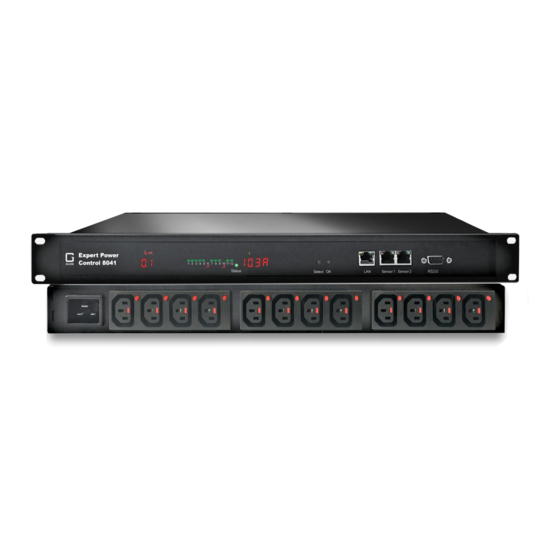
Device Description Installation The Expert Power Control 8041/8045 comes in two variants. Once with the original dis- play (revision 1). 1. 12 plain text displays (on/off) for the state of the outputs 2. LED indicator for Over-Voltage Protection (red - surge protection is inactive) 3. -
Page 9: Overvoltage Protection
Device Description 9. RS232 connector Expert Power Control 8041/8045 - 1 10. Mains supply (IEC C20, max.16 A) 11. 12 x Load outputs (IEC C13, max. 16 A) Expert Power Control 8041/8045 - 2 12. Mains supply (IEC C20, max.16 A) 13. -
Page 10: Technical Specifications
Device Description · An green flash means that the protection is active, a red flash symbolizes that the overvoltage protection fails. (Revision 2 device) In addition, the status of the overvoltage protection can be seen on the Webpage (HTTP) and acquired with SNMP. Each surge protection module is designed that it can derive a practical unlimited number of voltage pulses in normal installation environments. -
Page 11: Electrical Measurement
Device Description 1.6.1 Electrical Measurement typical fault tolerances for Ta=25°C, I=1Arms...16Arms, Un=90Vrms...265Vrms Electrical Measurement Specification Category Range Unit Resolu- Inaccuracy tion (typical) Voltage 90-265 0.01 < 1% Current 0 - 16 0.001 < 1.5% Frequency 45-65 0.01 < 0.03% Phase -180 - +180 °... - Page 12 Device Description Product Name 7101 7104-1 7105-1 7106-1 Calibrated 7104-2 7105-2 7106-2 Sensor Cable length Connector RJ45 RJ45 RJ45 RJ45 temperature range -20°C to +80°C at -20°C to +80°C at -20°C to +80°C at -20°C to +80°C at ±2°C (maximum) ±2°C (maximum) ±2°C (maximum) ±2°C (maximum)
- Page 13 Device Description A click on the link in the "Name" column opens the display of the Min and Max values. The values in a column can be reset using the "Reset" button. The "Reset" button in the name column deletes all stored Min and Max values. Expert Power Control 8041/8045 ©...
-
Page 14: Operating
Operating... -
Page 15: Operating The Device Directly
Operating Operating Operating the device directly Port Switching The current switching state of the output is indicated by the corresponding plain text dis- plays (port LEDs). If the green "on" LED is lit, the port is switched on, if the red "off" LED is lit, the output port is switched off. - Page 16 Operating The web page provides an overview of the switching state, energy measurement values, as well as the external sensors, provided that they are connected. The number of ports shown depends on the model. When a single port is clicked at the Expert Power Con- trol 8041/8045, a panel with buttons to control a single port appear: The Port icon is green when the relay is closed, or red in the open state.
-
Page 17: Maintenance
Operating The ports can be switched manually with the "On" and "Off" buttons. If the port is turned on, it can be turned off by pressing the "Reset" button, until after a delay it turns itself on again. The delay time is determined by the parameter Reset Duration, which is de- scribed in the chapter "Configuration - Power Ports ". - Page 18 Operating On the Maintenance Page , select the required file with "Browse .." in the sections "Firmware Update", "SSL Certificate Upload" or "Config Import File Upload" and press "Upload". The file is now transferred to the update area of the device and the contents are checked.
- Page 19 Operating Interface GBL_Conf To check the network settings with GBL_Conf.exe, start the program and choose "All Devices" in the "Search" menu. From the list select the appropriate device. The lower part of the left half of the window now shows the current network settings of the device. If the IP address is displayed with the default settings (192.168.0.2), either no DHCP server is present on the network, or there could be no free IP address assigned to it.
-
Page 20: Maintenance Page
Operating 2.3.1 Maintenance Page This section provides access to important functions such as Firmware Update or Restart Device. It is advisable to set an HTTP password for this reason. Firmware Update: Start a firmware update. SSL Certificate Upload: Saves your own SSL certificate. See chapter "SSL "... -
Page 21: Configuration Management
Operating Enter Bootloader Mode: Jumps into bootloader mode, where additional settings can be made with GBL_Conf.exe. Flush DNS Cache: All entries in the DNS cache are discarded and address resolutions are requested again. Config/Status View: status.html: Displays the status.html page with the JSON data. Config/Status Download: export.json: Direct file download of JSON data from status.hml. -
Page 22: Bootloader Activation
Operating modify the configuration state. It may be desirable to make the changes relative to the current configuration, and not out of the factory state. Then the "system fabsettings" should be removed. No output of default values The configuration file contains (with exceptions) only values which differ from the default. The command "system fabsettings"... - Page 23 Operating 3) by Software: · Start the "GBL_Conf.exe" program · Do a network search with the "Search" menu action · Activate in menu "Program Device" the item "Enter Bootloader" This function is only possible if "Enable FW to BL" was activated in the application "GBL_Conf.exe"...
- Page 24 Operating · Hold down the button (or the "Select" button for devices with 2 buttons) for 6 seconds. If the push button is recessed, use a pin or paper clip · The status LED will blink in a fast rhythm, please wait until the LED blinks slowly (about 5 seconds) 2) by Software: ·...
-
Page 25: Configuration
Configuration... -
Page 26: Power Ports
Configuration Configuration TCP/IP configuration by DHCP After switching on the device is scanning on the Ethernet for a DHCP server and re- quests an unused IP address. Check the IP address that has been assigned and adjust if necessary, that the same IP address is used at each restart. To turn off DHCP use the software GBL_Conf.exe or use the configuration via the web interface. -
Page 27: Watchdog
Configuration corresponds to a period of approx. two hours and 20 minutes. A value of zero means that the initialization is off. GSM Portcode (only GSM devices): Sets the individual port access code. Repower delay: When this feature is enabled (value greater than 0), the power port will switch itself on again a specified time after it has been disabled. - Page 28 Configuration Enable watchdog: Enables the watchdog function for this Power Port. Watchdog type: Here you can choose between the monitoring by ICMP pings or TCP pings. · ICMP Pings: The classic ping (ICMP echo request). It can be used to check the ac- cessibility of network devices (for example, a server).
-
Page 29: Ethernet
Configuration Ethernet 3.2.1 IP Address Hostname: Here you can enter a name with up to 63 characters. This name will be used for registration on the DHCP server. Special characters and umlauts can cause problems in the network. IPv4 Address: The IP address of the device. IPv4 Netmask: The network mask used in the network. - Page 30 Configuration to make global IPv6 addresses available. Use DHCP v6: Requests from an existing DHCPv6 server addresses of the configured DNS server. Use manual IPv6 address settings: Activates the entry of manual IPv6 addresses. IPv6 status: Displays the IPv6 addresses over which the device can be accessed, and additionally DNS and router addresses.
-
Page 31: Ip Acl
Configuration 3.2.2 IP ACL Reply ICMP ping requests: If you enable this feature, the device responds to ICMP pings from the network. Enable IP filter: Enable or disable the IP filter here. The IP filter represents an access control for incoming IP packets. Please note that when IP access control is enabled HTTP and SNMP only work if the appropriate servers and clients are registered in the IP access control list. -
Page 32: Http
Configuration 3.2.3 HTTP HTTP Server option: Selects whether access is possible only with HTTP, HTTPS, or both. Server port HTTP: Here can be set the port number of the internal HTTP. Possible values are from 1 to 65534 (default: 80). If you do not use the default port, you must append the port number to the address with a colon to address the device from a web browser. -
Page 33: Protocols
Configuration Use radius server passwords: Username and password are validated by a Radius Sever. Use locally stored passwords: Username and password are stored locally. In this case, an admin password and a user password must be assigned. The password can have a maximum of 31 characters. - Page 34 Configuration Telnet Enable Telnet: Enables the Telnet console. Telnet TCP port: Telnet sessions are accepted on this port. Raw mode: The VT100 editing and the IAC protocol are disabled. Active negotiation: The IAC negotiation is initiated by the server. Activate echo: The Telnet echo setting if not changed by IAC. Push messages: Sends push messages via SSH.
-
Page 35: Syslog
Configuration Enable serial console: Enables the serial console. Raw mode: The VT100 editing is disabled. Activate echo: The echo setting. Enable binary KVM protocol: Additionally activates the KVM protocol. Enable UTF8 support: Enables character encoding in UTF8. Push messages: Sends push messages via serial console. Require user login: Username and password are required. -
Page 36: Snmp
Configuration Enable Syslog: Enables the usage of Syslog Messages. Syslog Server: If you have enabled Syslog Messages, enter the IP address of the server to which the syslog information should be transmitted. 3.3.3 SNMP SNMP-get: Enables the acceptance of SNMP-GET commands. SNMP-set: Allows the reception of SNMP-SET commands. - Page 37 Configuration Because of security issues, it is advisable to use only SNMP v3, and to disable SNMP v2. Accesses to SNMP v2 are always insecure. Community public: The community password for SNMP GET requests. Community private: The community password for SNMP SET requests. Enable SNMP v3: Activates SNMP v3.
-
Page 38: Radius
Configuration 3.3.4 Radius Enable Radius Client: Enables validation over Radius. Use CHAP: Use CHAP password encoding. Use Message Authentication: Adds the "Message Authentication" attribute to the Authentication Request. Primary Server: Name or IP address of the Primary Radius server. Shared secret: Radius Shared Secret. For compatibility reasons, only use ASCII charac- ters. -
Page 39: Modbus Tcp
Configuration Retries: How often an authentication request is repeated after a timeout. Test Username: Username input field for Radius test. Test Password: Password input field for Radius test. The "Test Radius Server" function allows you to check whether a combination of User- name and Password is accepted by the configured Radius Servers. -
Page 40: Mqtt
Configuration 3.3.6 MQTT Enable MQTT: Enables MQTT support. Broker: DNS or IP address of the MQTT broker. TLS: Turns on TLS encryption. Mode TCP port: The TCP/IP port number of the broker. Username: The MQTT username. password: The password for the username. Client ID: The MQTT client ID. -
Page 41: Clock
Configuration MQTT Logs: Outputs individual log messages about the connection setup. MQTT Broker Status: Time information about connection duration, the last publish and the last keep-alive. Clock 3.4.1 Enable Time Synchronization: Enables the NTP protocol. Primary NTP server: IP address of the first NTP server. Backup NTP server: IP address of the second NTP server. -
Page 42: Timer
Configuration Daylight Saving Time: If enabled, the local time is converted to Central European Sum- mer Time. set manually: The user can set a time manually. set to Browsertime: Sets the time corresponding to web browser. If Time synchronization is enabled, a manual time will be overwritten at the next NTP synchronization. - Page 43 Configuration Creating a simple timer If you activate "New Rule: simple Timer" the following dialog is displayed: You set here which port should be switched for which time period, and on which days of the week the rule is active. In this example the period 9:00 to 17:00 is changed to 9:30 to 11:00 compared to the default input mask.
- Page 44 Configuration If you create a complex timer or change an existing timer, you will always see an exten- ded dialog. Here, ports can be switched as well as other actions can be executed via CLI commands. The setting of the switching times is more granular. You can see here the extended representation of the first rule of the simple timer from the previous example.
- Page 45 Configuration The switching function can be set in more detail on the "Action PortSwitch" register. Port 1 is switched on. You could extend the rule and switch more ports on or off. Addi- tionally you can set a time for a batchmode in the field after "Between Action1 and Ac- tion 2 : wait", which starts "Action 2"...
- Page 46 Configuration 17:10 and 17:30 would be programmed. To change a field in this input mask without changing the state of the other fields, the Ctrl key must be pressed during the mouse click. For this rule, on the "Options" tab, the time period is limited to the range between 5.10.2021 and 5.4.2022.
- Page 47 Configuration Instead of switching a port, one or more console commands can be executed. These commands are entered in the "Action CLI" register. The "Action Cli" tab can only be se- lected if the option "Perform CLI Cmd" is activated in "Options". Example Switching a Port on a Date If you want to switch on a timer on a certain date at a certain time and switch it off at a later time, you cannot do it directly with a simple timer.
- Page 48 Configuration Then call up the two timer rules you created ("On" and "Off") and enter the date on which the switching operation is to take place in the "Options" tab. Example blind control You can use the jitter e.g. for a shutter control. In the classic example of a shutter con- trol, you do not always want to raise and lower the shutters at the same time in order to confuse potential burglars.
-
Page 49: Sensors
Configuration Sensors Sensor: Selects a type of sensor to configure it. The first digit "1" indicates the number of the sensor port (only important for devices with more than one sensor port). This is fol- lowed by the sensor name, and the changeable sensor name. Sensor Name: Changeable name for this sensor. -
Page 50: Port Switching
Configuration devices only). In this example screenshot the recipient "user1" is activated, SMS send- ing for "user2" is deactivated. With the beeper you can choose between a continuous or an intermittent tone. With Flashing Display the 7-segment display flashes. By pressing a front panel button the beeper and the flashing display will be reset. - Page 51 Configuration Actions during configuration, device start or plugging in the sensor (for given example): actual temperature actions during configuration 70 °C Port A1 Off (above max) + Port A2 On (above min) 45 °C Port A1 On (below max) + Port A2 On (above min) 20 °C Port A1 On (below max) + Port A2 Off (below min) Action matrix during operation when limit values are exceeded (for given example):...
-
Page 52: E-Mail
Configuration E-Mail Enable E-Mail: Activates the E-Mail dispatch of messages. Sender address: The E-Mail address of the sender. Recipient address: The E-Mail address of the recipient. Additional E-Mail addresses, separated by comma, can be specified. The input limit is 100 characters. SMTP Server: The SMTP IP-address of the E-Mail server. -
Page 53: Front Panel
Configuration Front Panel Button Lock: Disables the front buttons (activates the key lock) with the exception of the bootloader activation. Allow switching all ports: Allows to switch all ports on or off with the front panel buttons. Display X default: Selects the display of sensor values for both displays. (Revision 1 devices have only one display) Expert Power Control 8041/8045 ©... -
Page 54: Specifications
Specifications... -
Page 55: Automated Access
Specifications Specifications Automated Access The device can be accessed automatically via four different interfaces, which offer differ- ent possibilities to access the configuration data and status information. Only http and the console (telnet and serial) provide full access to the device. This chapter is general for all Gude devices. - Page 56 Specifications lowing message types are supported: · Sending of e-mails · SNMP Traps · Syslog messages E-Mail messages Email messages are triggered by the following events: · Switching of the Ports · Exceeding of the max / min values of attached sensors ·...
- Page 57 Specifications RMS, DC differential current type Time-Interval external sensors Current, differential current type RMS, DC differential current type Value-Delta external sensors Current, differential current type RMS, DC differential current type SNMP traps There are common traps for state changes of the same device resource. For example, a SwitchEvtPort trap is sent when a port is turned on or off.
-
Page 58: Ip Acl
Specifications IP ACL IP Access Control List The IP Access Control List (ACL IP) is a filter for incoming IP packets. If the filter is act- ive, only the hosts and subnets whose IP addresses are registered in the list, can con- tact via HTTP or SNMP, and make changes. -
Page 59: Radius
Specifications 1234:4ef0::19:32ff:fe00:124 One may use the usual decimal notation of IPv4 for the last 4 bytes: 1234:4ef0::19:32ff:254.0.1.36 Radius The passwords for HTTP, telnet, and serial console (depending on the model) can be stored locally and / or authenticated via RADIUS. The RADIUS configuration supports a primary server and a backup server. - Page 60 Specifications the device messages are sent as notifications (traps). SNMP Informs are not supported. SNMP Requests are answered with the same version with which they were sent. The version of the sent traps can be set in the configuration. MIB Tables The values that can be requested or changed by the device, the so-called "Managed Ob- jects", are described in Management Information Bases (MIBs).
- Page 61 Specifications Passwords The passwords for authentication and encryption are stored only as computed hashes for security reasons. Thus it is, if at all, very difficult to infer the initial password. However, the hash calculation changes with the set algorithms. If the authentication or privacy algorithms are changed, the passwords must be re-entered in the configuration dialog.
-
Page 62: Device Mib 8041
Specifications So later you can use the 'subtree names' instead of OIDs: Name: snmpwalk -v2c -mALL -c public 192.168.1.232 gudeads OID: snmpwalk -v2c -mALL -c public 192.168.1.232 1.3.6.1.4.1.28507 NET-SNMP Examples Query Power Port 1 switching state: snmpget -v2c -mALL -c public 192.168.1.232 epc822XPortState.1 Switch on Power Port 1: snmpset -v2c -mALL -c private 192.168.1.232 epc822XPortState.1 integer 1 4.6.1... - Page 63 Specifications epc8041ActivePow erChan .85.1.5.1.1.0 Unsigned32 Number of suppported Pow er Channels. epc8041Pow erIndex .85.1.5.1.2.1.1.x Integer32 Index of Pow er Channel entries epc8041ChanStatus .85.1.5.1.2.1.2.x Integer32 0 = data not active, 1 = data valid epc8041AbsEnergyActive .85.1.5.1.2.1.3.x Gauge32 Absolute Active Energy counter. epc8041Pow erActive .85.1.5.1.2.1.4.x Integer32...
-
Page 64: Device Mib 8045
Specifications epc8041CPUSensorVsystem .85.1.5.14.1.0 Gauge32 System Voltage on CPU Board epc8041CPUSensorVaux .85.1.5.14.2.0 Gauge32 Auxiliary Voltage on CPU Board epc8041CPUSensorVmain .85.1.5.14.3.0 Gauge32 Main Voltage on CPU Board epc8041CPUSensorTcpu .85.1.5.14.4.0 Integer32 Temperature on CPU Board epc8041NTPTimeValid .85.1.5.15.1.0 INTEGER Show if valid Time is received epc8041NTPUnixTime .85.1.5.15.2.0 Unsigned32... - Page 65 Specifications epc8045TrapAddr .87.1.1.1.2.1.2.x OCTETS DNS name or IP address specifying one Trap receiver slot. A port can optionally be specified: 'name:port' An empty string disables this slot. epc8045portNumber .87.1.3.1.1.0 Integer32 The number of Relay Ports epc8045PortIndex .87.1.3.1.2.1.1.x Integer32 A unique value, greater than zero, for each Relay Port. epc8045PortName .87.1.3.1.2.1.2.x OCTETS...
- Page 66 Specifications epc8045Forw EnergyActiveResett .87.1.5.1.2.1.18.x Gauge32 able Resettable Forw ard Active Energy counter. epc8045Forw EnergyReactiveRes .87.1.5.1.2.1.19.x Gauge32 ettable Resettable Forw ard Reactive Energy counter. epc8045RevEnergyActive .87.1.5.1.2.1.20.x Gauge32 Reverse Active Energy counter. epc8045RevEnergyReactive .87.1.5.1.2.1.21.x Gauge32 Reverse Reactive Energy counter. epc8045RevEnergyActiveResetta .87.1.5.1.2.1.22.x Gauge32 Resettable Reverse Active Energy counter.
- Page 67 Specifications epc8045spForw EnergyReactive .87.1.5.5.2.1.17.x Gauge32 Forw ard Reactive Energy counter. epc8045spForw EnergyActiveRes .87.1.5.5.2.1.18.x Gauge32 ettable Resettable Forw ard Active Energy counter. epc8045spForw EnergyReactiveR .87.1.5.5.2.1.19.x Gauge32 esettable Resettable Forw ard Reactive Energy counter. epc8045spRevEnergyActive .87.1.5.5.2.1.20.x Gauge32 Reverse Active Energy counter. epc8045spRevEnergyReactive .87.1.5.5.2.1.21.x Gauge32 Reverse Reactive Energy counter.
-
Page 68: Ssl
Specifications TLS Standard The device is compatible with TLS v1.1 to TLS v1.3 standards, but due to lack of secur- ity, SSL v3.0, TLS 1.0, and RC4, MD5, SHA1, and DES encryption are disabled. All ciphers use Diffie-Hellman key exchange (Perfect Forward Secrecy). TLS 1.3 performance The interaction of TLS 1.3 and unsecure certificates and a web browser with Chromium Engine (Google Chrome or MS Edge) can lead to performance losses, and thus longer... -
Page 69: Console
Specifications with "-----BEGIN PRIVATE KEY-----", the file is in PKCS#8 format and the key is not re- cognized. If you have only a key in PKCS#8 format, you can convert it to PKCS#1 with openssl: "openssl rsa -in pkcs8.key -out pkcs1.key". ECC Certificate with Sign Request: openssl ecparam -genkey -name prime256v1 -out server.key openssl req -new -key server.key -out server.csr... - Page 70 Specifications There are several command levels. The following commands are usable from each level: back go back one level help all commands of the actual level help all show all commands logout logout (only when login required) quit quit console The "help"...
- Page 71 Specifications "{EVT_SYSLOG=0,EVT_SNMP=1,EVT_EMAIL=2,EVT_SMS=3,EVT_GSMEMAIL=4,EVT_BEEPER=5}" To set EVT_SYSLOG and EVT_EMAIL in a command, you can use the following syn- tax: >extsensor 1 2 0 events type set "EVT_SYSLOG,EVT_EMAIL" or numeric >extsensor 1 2 0 events type set "0,2" Additionally you can set all values with "ALLSET" or encode any bit pattern as hexa- decimal with a syntax like "#7f1a".
- Page 72 Specifications Raw Mode If you want to use the console only automated, it may be advantageous to set the con- figuration "Raw mode" to "yes" and "Activate echo" to "no" to. Then there is no interfer- ing interaction with the editor functions and the is no need to filter the sent characters to process the return values.
-
Page 73: Ssh
Specifications (12). >linesensor 1 "0,1,2,3,12" show >linesensor 1 1 show These variants give the sensor values of the field list or of a sensor at Line-In 1. For devices with Overvoltage Protection, the "linesensor all" command also outputs the state of the protection ("OVP=x"). A "1" means ok, a "0" a failure of the protection. c) Port Sensors >portsensor all "0,1,2,3,12"... - Page 74 Specifications The following public keys are accepted: Key type Length 2048, 4096 ECDSA 256, 384 Generation with PuTTYgen Generated keys can be copied directly from e.g. PuTTYgen, and inserted into the Configuration - Console input field. Public keys are accepted in SSH2 or OpenSSH format.
-
Page 75: Console Cmd 8041
Specifications 4.8.2 Console Cmd 8041 Command Description Note logout go to login prompt w hen enabled quit quits telnet session - nothing in serial console back back one cmd level help show all cmds from this level help all show all cmds clock enters cmd group "clock"... - Page 76 Specifications console ssh echo set {OFF=0|ON=1} enables echo on/off console ssh echo show show s if echo enabled console ssh pushmsgs config set {OFF=0|ON=1} enables persistent push msgs console ssh pushmsgs config show show s if persistent push msgs are enabled console ssh pushmsgs set {OFF=0|ON=1} enables temporary push msgs console ssh pushmsgs show...
- Page 77 Specifications show s all values from connected external extsensor all show sensors extsensor all show show s all plugged sensors and fields extsensor {port_num} {sen_field} value show show s sensor value extsensor {port_num} {sen_type} label set sets sensor name to label "{name}"...
- Page 78 Specifications BELOWMAX=3} state show extsensor period set {24H=0|12H=1|2H=2|1H=3| sets sensor Min/Max measurement period 30MIN=4} extsensor period show show s sensor Min/Max measurement period extsensor beeper set {OFF=0|ON=1} enables beeper sensor alarms extsensor beeper show show s if beeper sensor alarms are enabled http enters cmd group "http"...
- Page 79 Specifications ipacl ping enabled set {OFF=0|ON=1} enables ICMP ping on/off ipacl ping enabled show show s if ICMP ping enabled ipacl enabled set {OFF=0|ON=1} enable IP filter on/off ipacl enabled show show s if IP filter enabled ipacl filter {ipacl_num} set "{dns_name}" sets IP filter {ipacl_num} ipacl filter {ipacl_num} show show s IP filter {ipacl_num}...
- Page 80 Specifications linesensor {line_num} {energy_sensor} {BELOWMIN=0|ABOVEMIN=1|ABOVEMAX=2| show s Port for Pow er Port Sw itching actions BELOWMAX=3} port show linesensor {line_num} {energy_sensor} {BELOWMIN=0|ABOVEMIN=1|ABOVEMAX=2| sets Port state for Pow er Port Sw itching actions BELOWMAX=3} state set {OFF=0|ON=1| DISABLED=2} linesensor {line_num} {energy_sensor} show s Port state for Pow er Port Sw itching {BELOWMIN=0|ABOVEMIN=1|ABOVEMAX=2| actions...
- Page 81 Specifications mqtt {broker_idx} topic show shw os topic prefix mqtt {broker_idx} console enabled set {OFF=0| permit console cmds ON=1} mqtt {broker_idx} console enabled show show s if console cmds allow ed mqtt {broker_idx} device data timer set sets telemetry interval {num_secs} mqtt {broker_idx} device data timer show show s telemetry interval...
- Page 82 Specifications radius {PRIMARY=0|SECONDARY=1} server set sets radius server address "<dns_name>" radius {PRIMARY=0|SECONDARY=1} server show s radius server address show radius {PRIMARY=0|SECONDARY=1} passw ord sets radius server shared secret set "{passw d}" radius {PRIMARY=0|SECONDARY=1} passw ord sets radius server crypted shared secret hash set "{passw d}"...
- Page 83 Specifications rcmb {mod_num} {RMS=0|DC=1} {BELOWMIN=0| ABOVEMIN=1|ABOVEMAX=2|BELOWMAX=3} port sets pow er port for sensor values action set {port_num} rcmb {mod_num} {RMS=0|DC=1} {BELOWMIN=0| ABOVEMIN=1|ABOVEMAX=2|BELOWMAX=3} port show s pow er port for sensor values action show rcmb {mod_num} {RMS=0|DC=1} {BELOWMIN=0| ABOVEMIN=1|ABOVEMAX=2|BELOWMAX=3} sets state for sensor values action state set {OFF=0|ON=1|DISABLED=2} rcmb {mod_num} {RMS=0|DC=1} {BELOWMIN=0| ABOVEMIN=1|ABOVEMAX=2|BELOWMAX=3}...
- Page 84 Specifications system flushdns flush DNS cache system uptime number of seconds the device is running system name show show s device name system version show show s actual firmw are version system display {disp_num} default extsensor show s external sensor {port_num} {sen_type} set {sen_field} system display {disp_num} default linesensor show s energy line sensor...
- Page 85 Specifications timer {rule_num} action console set "{cmd}" sets cmd string timer {rule_num} action console show show s cmd string timer {rule_num} action hash set "{data}" sets action binary form timer {rule_num} action hash show show s action binary form timer {rule_num} delete delete one timer timer delete all delete all timer...
-
Page 86: Console Cmd 8045
Specifications External Sensor Type Table "{sen_type}" Constants "{7x01=0|7x04=0|7x02=1|7x05=1|7x06=2}" Index Description Products Temperature 7001, 7101, 7201 Temperature 7004, 7104, 7204 Temperature, Humidity 7002, 7102, 7202 Temperature, Humidity 7005, 7105, 7205 Temperature, Humidity, Air Pressure 7006, 7106, 7206 External Sensor Field Table "{sen_field}" Index Description Unit... - Page 87 Specifications console telnet login show show s if login enabled console telnet login local set {OFF=0|ON=1} enables local login on/off console telnet login local show show s if local login enabled console telnet login radius set {OFF=0|ON=1} enables login for RADIUS on/off console telnet login radius show show s if RADIUS login enabled console telnet login delay set {OFF=0|ON=1}...
- Page 88 Specifications email port set {ip_port} sets email SMTP port email port show show s email SMTP port email security set {NONE=0|STARTTLS=1|SSL=2} sets SMTP connection security email security show show s SMTP connection security email auth set {NONE=0|PLAIN=1|LOGIN=2} sets email authentication email auth show show email authentication email user set "{username}"...
- Page 89 Specifications extsensor {port_num} {sen_type} {sen_field} sets publish time interval publish timer set {num_secs} extsensor {port_num} {sen_type} {sen_field} show s publish time interval publish timer show extsensor {port_num} {sen_type} {sen_field} sets publish delta value publish delta set {float} extsensor {port_num} {sen_type} {sen_field} show s publish delta value publish delta show extsensor {port_num} {sen_type} {sen_field}...
- Page 90 Specifications enters cmd group "ip6" ip6 enabled set {OFF=0|ON=1} enables IPv6 on/off ip6 enabled show show s if IPv6 is enabled ip6 routadv enabled set {OFF=0|ON=1} enables IPv6 router advertisement ip6 routadv enabled show show s IPv6 router advertisement state ip6 dhcp enabled set {OFF=0|ON=1} enables IPv6 DHCP on/off ip6 dhcp enabled show...
- Page 91 Specifications linesensor {line_num} {energy_sensor} publish mode set {NONE=0|INTERVAL=1|DELTA=2| sets publish mode INTERV_DELTA=3} linesensor {line_num} {energy_sensor} publish show s publish mode mode show linesensor {line_num} {energy_sensor} publish sets mqtt retain mqtt retain set {OFF=0|ON=1} linesensor {line_num} {energy_sensor} publish show s if mqtt retain set mqtt retain show linesensor {line_num} {energy_sensor} publish sets publish time interval...
- Page 92 Specifications mqtt enters cmd group "mqtt" mqtt {broker_idx} enabled set {OFF=0|ON=1} enable mqtt mqtt {broker_idx} enabled show show s if mqtt enabled mqtt {broker_idx} server set "{dns_name}" sets broker name mqtt {broker_idx} server show show s broker name mqtt {broker_idx} tls enabled set {OFF=0|ON=1} enable TLS mqtt {broker_idx} tls enabled show show s if TLS enabled...
- Page 93 Specifications port {port_num} w atchdog link dow n show show s if w atchdog active w hen eth link dow n port {port_num} w atchdog host set "{dns_name}" sets port w atchdog host target port {port_num} w atchdog host show show s port w atchdog host target port {port_num} w atchdog port set {ip_port} sets port w atchdog TCP port...
- Page 94 Specifications portsensor {port_num} {energy_sensor} publish sets publish delta value delta set {float} portsensor {port_num} {energy_sensor} publish show s publish delta value delta show portsensor {port_num} {energy_sensor} {BELOWMIN=0|ABOVEMIN=1|ABOVEMAX=2| sets pow er port for sensor values action BELOWMAX=3} port set {port_num} set portsensor {port_num} {energy_sensor} {BELOWMIN=0|ABOVEMIN=1|ABOVEMAX=2| sets state for sensor values action...
- Page 95 Specifications radius chap enabled set <off=0/on=1> enables CHAP radius chap enabled show show s if CHAP is enabled radius message auth set <off=0/on=1> enables request message authentication show s if request message authentication is radius message auth show enabled sets default session timeout (w hen not returned radius default timeout set {num_secs} as Session-Timout Attribute) radius default timeout show...
- Page 96 Specifications snmp port show show s SNMP UDP port snmp snmpget enabled set {OFF=0|ON=1} enables SNMP GET cmds on/off snmp snmpget enabled show show if SNMP GET cmds are enabled snmp snmpset enabled set {OFF=0|ON=1} enables SNMP SET cmds on/off snmp snmpset enabled show show if SNMP SET cmds are enabled snmp snmpv2 enabled set {OFF=0|ON=1}...
- Page 97 Specifications system {SWITCH_PORT=0} events set {OFF=0| enable global events ON=1} system {SWITCH_PORT=0} events show show s if global events enabled system {SWITCH_PORT=0} events type set "{EVT_SYSLOG=0,EVT_SNMP=1,EVT_EMAIL=2,E VT_SMS=3,EVT_GSMEMAIL=4,EVT_BEEPER=5,E enables different event types VT_DISPLAY=6,EVT_CONSOLE=7,EVT_MQTT=8} " system {SWITCH_PORT=0} events type show show s w hat event types are enabled system {SWITCH_PORT=0} events mqtt retain set sets mqtt retain {OFF=0|ON=1}...
- Page 98 Specifications Notes 1. Legacy - The command has been replaced by a newer version 2. Command can be entered on any level 3. The output may show 2 lines - the 1st line shows the actual state, the 2nd line the status after reboot 4.
-
Page 99: Serial Console
Specifications Temperature, Humidity, Air Pressure 7006, 7106, 7206 External Sensor Field Table "{sen_field}" Index Description Unit Temperature °C Humidity Digital Input bool Air Pressure Dew Point °C Dew Point Temperature Difference °C 4.8.4 Serial Console If the device has a serial port, the entire console command set for Telnet is also available at the serial console. -
Page 100: Modbus Tcp
Specifications Port Power On Power Off 0x80 0x31 0x01 0x30 0x80 0x32 0x01 0x33 0x80 0x31 0x02 0x33 0x80 0x32 0x02 0x30 0x80 0x31 0x0C 0x3D 0x80 0x32 0x0C 0x3E Modbus TCP Important: All calculations in this chapter are based on addresses starting at "0". For some Modbus TCP Utilities, however, the addresses start at 1, in which case a 1 must be added to the addresses in this chapter. - Page 101 Specifications Write Multiple Coils 0x0f Read Input Registers 0x04 Read Holding Registers 0x03 Write Holding Register 0x06 Write Multiple Holding Registers 0x10 Read Device Identification 0x2B / 0x0E Coils Device Resource Start Device Function Power/Output/eFuse 0x000 0x3ff Coil represens Port State Discrete Inputs Device Resource Start...
- Page 102 Specifications 16-bit Number of Ports (Relay) 16-bit Number of Ports (Outlets) with Energy Measurement 16-bit Number of Banks 16-bit Number of Line-In 16-bit Phases per line 16-bit Number of Inputs Sensor Type Description Address Width Information 0x080 to 0x083 16-bit (signed CPU Sensor values 0x100 to 0x1ff 16-bit (signed)
- Page 103 Specifications Energy Sensors: We distinguish the line sensors (which correspond to the input circuits) and the port sensors, which measure the energy that is passed over the switched port. The meas- ured values of the energy sensors are returned as signed 32-bit integers. The high-order 16-bits are starting on the even address, followed by the low-order 16-bits on the odd ad- dress.
- Page 104 Specifications ted depends on the respective device model. For measured values such as "Neutral Cur- rent", which are independent of the phase, the same value is returned for all phases. DC Energy Sensors: With the EPC 8291 / 8290 devices, the voltage and current of the individual banks and voltage sources can be read out.
-
Page 105: Sensor Tables
Specifications Device Resource Start Function Bank Power Source 0x000 0x00f Sets Power Source for Bank Fan Mode 0x010 0x01f 0 = Automatic / 1 = Maximum Device Identification Returns manufacturer name and device identification: Request Code 1 Byte 0x2b MEI Type 1 Byte 0x0e Read Dev ID code... - Page 106 Specifications A value of 0x8000 means that no sensor is plugged into the corresponding port or the corresponding field in the sensor is not available. Line-In Energy Addresses (Input Register) Offset Sensor Field Line 1 Absolute Active Energy 0x400 Power Active 0x402 Voltage 0x404...
-
Page 107: 4.10 Mqtt
Specifications 0x3a18 0x3b38 0x3c58 0x3d78 0x3e98 0x3fb8 0x3a1a 0x3b3a 0x3c5a 0x3d7a 0x3e9a 0x3fba 0x3a1c 0x3b3c 0x3c5c 0x3d7c 0x3e9c 0x3fbc 0x3a1e 0x3b3e 0x3c5e 0x3d7e 0x3e9e 0x3fbe 0x3a20 0x3b40 0x3c60 0x3d80 0x3ea0 0x3fc0 0x3a22 0x3b42 0x3c62 0x3d82 0x3ea2 0x3fc2 0x3a24 0x3b44 0x3c64 0x3d84 0x3ea4 0x3fc4... - Page 108 Specifications · If multiple MQTT clients are connected to a broker, the names of the clients must be different. For this reason, "client_xxxx" is generated as the default name. Here "xxxx" are the last 4 digits of the MAC address. Message format The MQTT messages of the device are always sent in JSON format.
- Page 109 Specifications Response from device to "de/gudesystems/epc/00:19:32:01:16:41/cmdres/cli" "OK." Format 3: Simplified port switching Publish Topic: "de/gudesystems/epc/00:19:32:01:16:41/cmd/port/2" Publish Message: "0" or "1". Response from device to "de/gudesystems/epc/00:19:32:01:16:41/cmdres/port/2" "0" or "1" This special form exists only for the port switching commands. Device Data Summary In the Device Data Summary the most important data of the device are summarized in a JSON object and sent periodically in a configurable time interval.
-
Page 110: Example Hivemq
Specifications "field": "dew_point", "v": 15.8, "unit": "deg C" }, { "field": "dew_diff", "v": 5.3, "unit": "deg C" "ts": 210520 4.10.1 Example HiveMQ What does an MQTT configuration look like using HiveMQ as an example? Create a free or commercial account at www.hivemq.com and create a new cluster. In the "Manage Clusters"... - Page 111 Specifications In the MQTT configuration of the Gude device, transfer the hostname of the HiveMQ broker, as well as username and password. Additionally activate TLS and set the correct port. Expert Power Control 8041/8045 © 2022 GUDE Systems GmbH...
-
Page 112: Support
Support... -
Page 113: Data Security
Support Support You will find the latest product software on our website at www.gude.info available for download. If you have further questions about installation or operation of the unit, please contact our support team. Furthermore, we present in our support wiki at www.gude.info/wiki FAQs and configuration examples. -
Page 114: Declaration Of Conformity
Support District Court: Köln, HRB-Nr. 17 7 84 WEEE-number: DE 58173350 Value added tax identification number (VAT): DE 122778228 Declaration of Conformity This product from the Expert Power Control 8041 / 8045 series is in conformity with the European directives for CE marking applicable to this product. The complete CE de- claration of conformity for this product can be found on the website www.gude.info in the download section of the product. - Page 115 Support The serial number is not stored in the device, but only visible on the device label. However, you can display the MAC address in the IP address configuration . If you contact Gude Systems Support with the MAC address, we will be happy to give you the corresponding serial number.
-
Page 116: Index
Index - A - - I - automated Access Installation IP-ACL 31, 58 - B - IP-Address IPv6 Bootloader Mode 17, 22 - L - Button Lock - C - load Configuration - M - Certificate-Upload 17, 20 clear DNS-Cache Configuration Management Maintenance Content of Delivery... - Page 117 Index Status-LED syslog - T - Technical Specifications Timer Timer Configuration - W - Watchdog Expert Power Control 8041/8045 © 2022 GUDE Systems GmbH...
- Page 118 Expert Pow er Control 8041/8045 © 2022 GUDE Systems GmbH 3/16/2022 Expert Power Control 8041/8045 © 2022 GUDE Systems GmbH...
Need help?
Do you have a question about the Expert Power Control 8041 Series and is the answer not in the manual?
Questions and answers