Table of Contents
Advertisement
Quick Links
Advertisement
Table of Contents

Subscribe to Our Youtube Channel
Related Manuals for Panduit Smartzone UPS INTELLIGENT NMC


Summary of Contents for Panduit Smartzone UPS INTELLIGENT NMC
- Page 1 User Manual UPS Network Management Card Version 1.1...
-
Page 2: Table Of Contents
Network Settings......................19 System Management Information ................23 Setting Time and Date on the NMC ................26 Control & Manage ...................... 28 Panduit’s Smart Load Shedding ................38 Email Setup ....................... 45 Event Log ........................48 Data Log ........................49 Web Interface Access .................... - Page 3 Secure deployment ....................77 Warranty and Regulatory Information................80 Warranty Information ....................80 Regulatory Information ....................80 Panduit Support and Other Resources ................81 Accessing Panduit Support ..................81 Acronyms and Abbreviations ..................82 Appendix A: Firmware Update Procedure ..............98 Appendix B: System Reset or Password Recovery ............
- Page 4 INTELLIGENT NMC USER MANUAL...
- Page 5 Table of Figures Figure 1: Ethernet Port for Network Connection .............. 8 Figure 2: Serial In Port ....................9 Figure 3: Network information from CLI ................. 10 Figure 4: Refused Connection Example ................ 11 Figure 5: Certificate Warning ..................12 Figure 6: Login Page .....................
- Page 6 Figure 37: Cancel Test Confirmation ................33 Figure 38: Battery Test Configuration................34 Figure 39: UPS Mode Example ..................34 Figure 40: Edit Outlet Group ..................35 Figure 41: Outlet Group Control ..................36 Figure 42: Edit Outlets ....................37 Figure 43: One Delay Time ...................
- Page 7 Figure 75: Dry Contact Sensor Edit dialog ..............73 Figure 76: SSL Certificate Load Screen ............... 78 Figure 77: Upload Firmware ..................98 Figure 78: Control Panel ..................... 100 Figure 79: Network Status and Tasks ................. 101 Figure 80: Change Adapter Settings ................102 Figure 81: Properties ....................
-
Page 8: Section 1 - System Overview
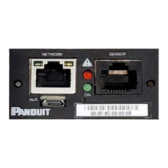
IP address, and it can be obtained using the instructions in Appendix C: Direct connect to the UPS via Ethernet without Bonjour. The NMC supports mDNS to discover the DHCP IP or the Auto IP. The mDNS address format is “panduit- ups-nmc-<macaddress>.local”. For example, the mDNS address for Figure 1 corresponds to “panduit-ups-nmc-000F9C03000B.local”... -
Page 9: Connecting The Nmc To A Computer Serial Port
Connecting the NMC to a Computer Serial Port If unable to connect to a network, you can retrieve the network setting using the serial interface. To discover the network setting, perform the following steps: 1. Connect PC to the NMC USB port. See Figure 2: Serial In Port. 2. -
Page 10: Figure 3: Network Information From Cli
Figure 3: Network information from CLI INTELLIGENT NMC USER MANUAL... -
Page 11: Section 2 - Web Graphical User Interface (Gui)
Section 2 – Web Graphical User Interface (GUI) Internet Protocol (IP) Addressing After the NMC receives an IP address, login to the Web interface to configure the NMC and assign a static IP address (if desired). Web Connection Supported Web Browsers The supported Web browsers are Google Chrome (mobile and desktop), Mozilla Firefox, Microsoft Edge and Apple Safari (mobile and desktop). -
Page 12: Figure 5: Certificate Warning
Figure 5: Certificate Warning o If username and password have NOT been configured, use the default username: admin and password: admin. For security purposes, a change of password is required upon initial login. o If admin credentials are lost use Appendix C to factory reset the NMC. -
Page 13: Figure 7: Changing Your Password
c. Contain at least one number. d. Contain at least one special character. Figure 7: Changing Your Password 2. Click Log In to complete the password change. After the initial login, change the password by the following steps: 1. Click on the username and select Change Password. Figure 8: After Login 2. -
Page 14: Introduction To The Web Gui
Changing Your Password Introduction to the Web GUI Remember: https:// must be used (for initial login) Landing Page/Dashboard Figure 9: Landing Page/Dashboard Number Icon Description The home icon provides an overview of the UPS with access to the Dashboard, Identification, and Control & Manage. The Alarm icon provides details of the active alarms. - Page 15 Number Icon Description This icon shows who is logged in (user or admin). Account passwords can be changed, and user accounts managed through this page. Menu Dropdowns Overview Alarms Language Logs Setting Help User INTELLIGENT NMC USER MANUAL...
-
Page 16: Introduction To The Dashboard
Introduction to the Dashboard Power Summary Page Figure 10: Power Summary Page NUMBER DESCRIPTION Power flow of the system. The state will be Normal, Bypass or On Battery, None The bypass component of the UPS The AC input source The AC to DC converter (Rectifier) INTELLIGENT NMC USER MANUAL... -
Page 17: Figure 11: Ups Monitoring Page
The DC to AC converter (Inverter) The Output Load The Battery Alert Summary. Clicking on the icon will give a summary of the system. Speaker Status. If the audible alarm is enabled. Battery Status UPS Monitoring Page Figure 11: UPS Monitoring Page INTELLIGENT NMC USER MANUAL... -
Page 18: Figure 12: Environmental Monitoring Page
Environmental Monitoring Page Figure 12: Environmental Monitoring Page PARAMETER DESCRIPTION Type Temperature, Humidity, Water Sensor Name User configurable sensor name Serial Sensor Serial number Number Value Sensor reading Status Normal, Exceeds Thresholds, Alarms Security Monitoring Page Figure 13: Security Monitoring Page INTELLIGENT NMC USER MANUAL... -
Page 19: Network Settings
Network Settings The Network Settings allow management of IP Configuration, DNS, Web Access, SSH Configuration, Syslog Configuration, Network Time Protocol (NTP), Date/Time Configuration and Time Zone Configuration. IP Configuration: Figure 14: IP Configuration INTELLIGENT NMC USER MANUAL... -
Page 20: Figure 15: Dns Configuration
DNS configuration: Figure 15: DNS Configuration Web Access Configuration Web Access Configuration is used to set HTTP and HTTPS. Also, this section will be used to upload HTTPS Certificates. Figure 16: Web Access Configuration INTELLIGENT NMC USER MANUAL... -
Page 21: Figure 17: Ssh Configuration
SSH Configuration: Figure 17: SSH Configuration Syslog Configuration: Figure 18: Syslog Configuration Network Time Protocol (NTP) INTELLIGENT NMC USER MANUAL... -
Page 22: Figure 19: Network Time Protocol
Figure 19: Network Time Protocol Date/Time Configuration: Figure 20: Date/Time Configuration INTELLIGENT NMC USER MANUAL... -
Page 23: System Management Information
Time Zone Configuration: Figure 21: Time Zone Configuration System Management Information The system management information is a way to distinguish the UPS system’s name and location inside the data center. To configure the system management information, select System Management under the gear icon. -
Page 24: Figure 23: System Information Configuration
information: 1. Select the pencil icon next to System Management. Figure 23: System Information Configuration 2. Enter the System Name 3. Enter the name of the person who should be contacted if there is a problem with the system into the Contact Name section. 4. -
Page 25: Figure 24: Rack Location Configuration
Figure 24: Rack Location Configuration 2. Enter the room location of the rack or cabinet that contains the NMC system into Room Name. 3. Enter the name of row where the NMC is located in Row Name. 4. Enter the position of the row where the NMC is positioned in Row Position. 5. -
Page 26: Setting Time And Date On The Nmc
Figure 25: Power Panel & Core Location 2. Enter the name of the NMC in the Power Panel Name. 3. Select Front or Back for the Core Location. The Core Location is the side of the rack/cabinet where the NMCs are installed. For vertical NMCs, they are typically installed in the back. -
Page 27: Figure 27: Ntp Configuration
2. Enter the date using the MM/DD/YYYY format or use the calendar icon to select a date. 3. Enter the time in the three fields provided: the hour in the first field, minutes in the next field, and seconds in the third field. Time is measured in 24-hour format. Enter 13 for 1:00pm, 14 for 2:00pm, etc. -
Page 28: Control & Manage
The control and manage section of the Web GUI will allow a user to control the functionality of the system. These areas include the audible alarm, outlet control and battery test. Control & Manage also include management of Panduit’s Smart Load Shedding. -
Page 29: Figure 29: Control & Manage
Figure 29: Control & Manage Audible Alarm The UPS will emit an audible alarm from certain conditions on the system. To see the list of reasons and the behavior of the audible alarm review the UPS specific user manual. The audible alarm can be enabled of disabled through the Web GUI. Disabling the audible alarm will silence any alarm at the UPS. -
Page 30: Figure 31: Enter Bypass Example
Figure 31: Enter Bypass Example 3. The user will be asked to confirm they want to enter bypass. 4. Select YES to enter bypass or select No to cancel. Restore Normal Operation When the user desired the UPS to transition back to normal operation, the user can exit bypass. -
Page 31: Figure 32: Exit Bypass Example
Figure 32: Exit Bypass Example Battery Test Manual Battery Test Running the manual battery test is a two-step process. The user must first configure the type of the test to run and then initiate the test. Manual Test Configuration 1. Select the Home Icon then Control & Manage from the drop-down menu in the Web GUI 2. -
Page 32: Figure 34: Start Test Example
Note: The Full Discharge test leaves the battery in the low charge state. 4. If the test selected is Timed select the number of minutes to run the test. 5. Then select Save Manual Test Start 1. Select the Home Icon then Control & Manage from the drop-down menu in the Web GUI 2. -
Page 33: Figure 36: Cancel Test Example
Figure 36: Cancel Test Example 3. The user will be asked to confirm they want to cancel the in progress battery test. Figure 37: Cancel Test Confirmation 4. Select YES to cancel the test or select No to continue with the in-progress test. Running the manual battery test is a two-step process. -
Page 34: Figure 38: Battery Test Configuration
Figure 39: UPS Mode Example Outlet Group Control Naming an Outlet Group For Panduit UPS with outlet group control, you can customize each outlet group through the Web GUI. 1. Select the Home Icon then Control & Manage from the drop-down menu in the Web GUI 2. -
Page 35: Figure 40: Edit Outlet Group
5. Press Save. Setting the Outlet Group Default State Setting the Outlet Default State on Panduit UPSs with outlet level control allows the user to determine the initial power status of an individual outlet upon UPS power up. 1. Select the Home Icon then Control & Manage from the drop-down menu in the Web GUI 2. -
Page 36: Figure 41: Outlet Group Control
Switching an Outlet Group On or Off This is only applicable to outlet group switched UPSs. Outlets Groups on the switched UPS models are easily switched on, switched off, or rebooted. This action requires the user to have Administrator or Controller Privileges. Enabling Manual Outlet Group Control 1. -
Page 37: Figure 42: Edit Outlets
On: Immediately restore power to the outlet group. On Delayed: Wait “On Delay” then restore power to the outlet group. Setting the Outlet Power On/Off Delay for Panduit NMCs This is only applicable to outlet group switched UPS. 1. Select the Home Icon then Control & Manage from the drop-down menu in the Web GUI. -
Page 38: Panduit's Smart Load Shedding
1 is turned on. Panduit’s Smart Load Shedding Panduit’s Smart Load shedding allows the UPS to be configured to shed different loads depending on the configuration of the Shutdown Groups in order to maintain the battery for higher priority equipment. - Page 39 Next, configure any Smart Loads connected to the system to be properly shut down. A Smart Load is a device that can be shut down by a CLI command over an SSH connection or a Windows device running the Panduit Shutdown Agent. Finally, add the Smart Load to the correct Shutdown Group.
-
Page 40: Figure 44: Shutdown Group Configuration
Figure 44: Shutdown Group Configuration 4. Name the group. The Group Name is the name of the shutdown group to allow the user to denote the type of devices in the group. 5. Select the Shutdown Type. The Shutdown Type is ether Time on Battery or Battery Capacity. - Page 41 9. Select the Outlet Group that is associated with the Shutdown Group. 10. If Restore After Shutdown is selected, the associated Outlet Group will be toggle when the system transitions off the battery. Smart Loads Configuration Smart Loads are connected devices to the UPS that would need to be shutdown gracefully before the system’s battery is depleted.
-
Page 42: Figure 45: Smart Load Configuration
Figure 45: Smart Load Configuration 4. Enable the Smart Load by selecting Enable. If the Smart Load is not enabled, it will not be shut down when the associated shutdown group is shut down. 5. The Name will allow the user to associate a more meaningful name to the device. - Page 43 complete. 8. For ease of operation, you can select one of the common agent shutdown commands. Select one of the following options from the pull down menu.11 a. SSH Windows – This sends a “shutdown /s” to the remote server. b.
-
Page 44: Figure 46: Shutdown Schedule Configuration
Figure 46: Shutdown Schedule Configuration 4. Enable the schedule shutdown by selecting Enable. If the schedule is not enabled, it will not be shut down. 5. Select the associated shutdown groups. The user can select an individual group or All Groups 6. -
Page 45: Email Setup
8. Finally, the Duration. The duration is how long the shutdown group will remain shutdown. Email Setup The Panduit UPS NMC can be configured to send emails to specific users when an event occurs. To do this, the information about the SMTP (Simple Mail Transfer Protocol) server needs to be configured. -
Page 46: Figure 48: Smtp Account Settings
Figure 48: SMTP Account Settings • Set the SMTP server. This is the address of the SMTP relay server that is going to accept the messages. • Set the Sender email address. This is the email address that the email is sent from. - Page 47 • Configure the Port number. The port number is the communication endpoint on the server. The default is 25. Other common SMTP ports are 587 and 465 • If the SMTP server requires authentication, enter the username and password. These will be determined by the configuration on the SMTP server.
-
Page 48: Event Log
Figure 49: Email Recipient Enter the desired email address and press Enable. Press Save. Note: A maximum of 5 users can be entered to receive email alerts. Event Log UPS events and NMC events or alarms are recorded in the event log. Syslog can also be configured to report this to remotely. -
Page 49: Data Log
Figure 51: Event log Actions menu Data Log The period visible in the data log at any one time depends on the time between data log entries. The time range of each record can be configured from 1 to 1440 minutes. (As an example, if a data log is in an interval of 60 minutes, the entire data log contains 1000 records with up to 41.67 days of data.) Once the data log reaches the maximum of 1000 records, the oldest entries are overwritten by the newer entries. -
Page 50: Web Interface Access
Figure 53: Data Log Configuration 3. Enable must be selected and enter an interval number in the Log Interval field. (Valid range is from 1 to 1440 minutes. The default time is 60 minutes.) Figure 54: Data Log Configuration Panel 4. - Page 51 be added by a user with administrator privileges. The Controller role can control the UPS functionality, like outlet control and battery test, but cannot change the system settings. Users are defined by their unique login credentials and by their user role. The level of access privilege determines what the user will see and what actions the user can perform.
-
Page 52: Setting Up The System For Radius Authentication
a. Contain at least one lowercase character. b. Contain at least one uppercase character. c. Contain at least one number. d. Contain at least one special character. 4. Select Save to save the new user profile. Modify user profile: 1. Go to Settings and select Users. 2. -
Page 53: Configuring The System With Ldap Server Settings
Note: By default, a RADIUS user will have the “viewer” Role if one is not specified. The administrator of the RADIUS server may configure a Panduit vendor (19536) dictionary, with a “User-Role” integer attribute set to User (1) or Admin (2) or Control(3). For complete details, see... - Page 54 2. Select the LDAP Enable checkbox. 3. Use the drop-down menu to choose the Type of LDAP Server. Choose Microsoft Active Directory. 4. Enter an IP Address of the domain controller/Active Directory (AD) Server. e.g. 192.168.1.101 5. Enter a Port. Note: For Microsoft, this is typically 389.
-
Page 55: Figure 57: Ldap Configuration
With these LDAP settings configured, the Bind is complete. Figure 57: LDAP Configuration Once LDAP is configured, the UPS must understand for which group authentication occurs. A role must be created on the UPS to reference a group within the Active Directory (AD). -
Page 56: Figure 58: Enable Role Privileges
Figure 58: Enable Role Privileges LDAP authentication is ready to use. INTELLIGENT NMC USER MANUAL... -
Page 57: Section 3 - Simple Network Management Protocol (Snmp)
Section 3 – Simple Network Management Protocol (SNMP) SNMP Management Configuration Setup SNMP 1. Access the Web interface and login. 2. Under SNMP Managers, select SNMP General (or type SNMP in the search). The SNMP General page displays. Figure 59: SNMP Management INTELLIGENT NMC USER MANUAL... -
Page 58: Figure 60: Snmp General
3. The SNMP General includes SNMP Access and Version. Figure 60: SNMP General Setup SNMP Port 1. Access the Web interface and log in. 2. Under SNMP Managers, select SNMP Port. The SNMP Port page displays. Figure 61: SNMP Port 3. -
Page 59: Configuring Users For Snmp V1/V2C
Figure 62: Setup SNMP Port and Trap Port Configuring Users for SNMP V1/V2c 1. Access the Web interface and log in. 2. Under SNMP Manager, select SNMP V1/V2c. 3. In the SNMP V1/V2c panel, select the SNMP V1/V2c manager to configure. Select the pencil icon. -
Page 60: Configuring Users For Snmp V3
4. The Edit panel pop up displays. Figure 64: Edit V1/2c Manager 5. Set the following options: • IP Address: the IP address of the host for this SNMP V1/V2 manager. Only requests from this address will be acted upon. Note: An IP address configured to 0.0.0.0 will act as a wildcard and all requests will be acted upon. -
Page 61: Figure 65: Snmp V3 Manager
Figure 65: SNMP v3 Manager 4. The Edit panel pop-up displaying the configurable options. INTELLIGENT NMC USER MANUAL... -
Page 62: Figure 66: Snmp V3 Edit
Figure 66: SNMP V3 Edit 5. Configure the SNMP username 6. Choose a Security Level from the dropdown menu • NoAuthNoPriv: No authentication and no privacy. This is the default. • AuthNoPriv: Authentication and no privacy. INTELLIGENT NMC USER MANUAL... -
Page 63: Configuring Snmp Traps
• AuthPriv: Authentication and privacy. 7. Enter a new unique Authentication Password to be used for authentication. Repeat the authentication password below it in Confirm Password. 8. Select the desired authentication algorithm. • MD5 • SHA 9. Enter a new unique Privacy Key to be used with the privacy algorithm. Repeat the privacy key below it in Confirm Password. -
Page 64: Figure 67: Snmpv2C Trap Receiver Configuration Information
Figure 67: SNMPv2c Trap Receiver Configuration Information 3. Enter the Name, Host, and a Community name in the fields provided. a. The name is a user assigned name to help distinguish the different receivers. b. The host name is the IP Address to which the traps are sent by the SNMP system agent. -
Page 65: Figure 68: Snmpv3 Trap Server Configuration Information
Figure 68: SNMPv3 Trap Server configuration Information. 3. Enter the Name and Host name in the fields provided. a. The name is a user assigned name to help distinguish the different receivers. b. The host name is the IP Address to which the traps are sent by the SNMP system agent. - Page 66 5. Enter the Authentication Password from the SNMP Server to be used for authentication. Repeat the authentication password below it in Confirm Password. 6. Select the desired authentication algorithm. • MD5 • SHA 7. Enter the Privacy Key from the SNMP Server for privacy algorithm. Repeat the privacy key below it in Confirm Password.
-
Page 67: Section 4 - Network Management Controller
Section 4 – Network Management Controller Status LED The LED will change colors depending on the state of the UPS. LED State Description Green LED On / Red LED off Normal operation Red LED on NMC Initialization or NMC internal error condition Network LED The LED will change colors depending on the Ethernet link status and the speed. -
Page 68: Section 5 - Smartzone G5 Accessories
SmartZone G5 Sensors to 3 party controllers may result in damage. Note: A maximum of 8 sensors can be managed by the Panduit NMC controller. Sensors may be installed with NMCs powered on. The following table lists available sensors as well as sensor count:... -
Page 69: Configuring Temperature Scale
Sensor Description Sensor Count Sensor Port Hub (EF001) Passive hub allowing for three additional sensors to be connected. Leak Detection Sensor Extends the Rope type leak Extension (EG001) detector by an additional 6m. A total of four extensions can be added to the leak detection sensor for a total length of 30m. -
Page 70: Configuring Environmental Sensors
Figure 70: User Accounts 2. Select the pencil next to Region Figure 71: Temperature Units Setting 3. Select the correct units and select Save. Configuring Environmental Sensors To configure the sensor location, alarms, notifications, and details, open the WEB Interface: 1. -
Page 71: Configuring Security Sensors
Figure 72: Environmental Sensor Threshold Configuration View 3. Select pencil next to the desired sensors. 4. In the Edit dialog box, type the name of the sensor 5. Type value of high critical, high warning, low warning, and low critical and check Enable box. -
Page 72: Figure 74: Security Sensor Alarm Configuration View
2. View the Threshold section on the Settings page. Select Threshold to configure sensors. Figure 74: Security Sensor Alarm Configuration view 3. Select pencil next to the desired sensors. 4. In the Edit dialog box, type the name of the sensor 5. -
Page 73: Deleting Sensors
Figure 75: Dry Contact Sensor Edit dialog Deleting Sensors 1. Select Threshold from Settings menus 2. Select pencil next to the desired sensors 3. Check Delete box, then save. INTELLIGENT NMC USER MANUAL... -
Page 74: Section 6 - Security
Section 6 – Security This product contains software that stores user entered data. All data entered by the user is stored in non-volatile storage on the system running the software. Non-volatile Storage • The product uses encrypted non-volatile storage to store all configuration information. -
Page 75: Network Transport Security
Network Transport Security • The product generates a random SSH RSA 2048-bit private host key the first time the product starts up. • The product has a randomly generated RSA 2048-bit private key configured by the factory. This key is used to generate a HTTPS certificate the first time the product starts up. -
Page 76: External Authorization Mechanisms
• The product connects to user configured SSH servers using these algorithms: o Key exchange algorithms: ▪ ecdh-sha2-nistp256, ecdh-sha2-nistp384, ecdh-sha2-nistp521, diffie-hellman-group-exchange-sha256, diffie-hellman-group16- sha512, diffie-hellman-group18-sha512, diffie-hellman-group14- sha256, diffie-hellman-group14-sha1, diffie-hellman-group1-sha1, diffie-hellman-group-exchange-sha1 o Host key algorithms: ▪ ecdsa-sha2-nistp256 o Encryption algorithms: ▪ aes128-ctr, aes192-ctr, aes256-ctr, aes256-cbc, rijndael- cbc@lysator.liu.se, aes192-cbc, aes128-cbc, blowfish-cbc, arcfour128, arcfour, 3des-cbc o MAC algorithms:... -
Page 77: Secure Boot Protection
• The product includes a real-time clock and a capacitor that maintains time for a short amount of time when no power is applied. When combined with NTP, accurate timestamps on logs are provided. Secure deployment To maintain the highest level of security from, Panduit recommends the user configures INTELLIGENT NMC USER MANUAL... - Page 78 Figure 76: SSL Certificate Load Screen Use SNMPv3c The Panduit UPS NMC comes with support for both SNMPv2c and SNMPv3. For a higher security deployment, it is recommended to disable SNMPv2c. Another recommendation is to configure all SNMPv3 user and traps receiver with an “Auth Priv”...
- Page 79 Review Session management The NMC gives the customer the flexibility to change session management settings. INTELLIGENT NMC USER MANUAL...
-
Page 80: Warranty And Regulatory Information
Warranty and Regulatory Information Warranty Information (https://www.panduit.com) Regulatory Information Safety and regulatory compliance For important safety, environmental, and regulatory information, see Safety and Compliance Information at the Panduit website (https://www.panduit.com) INTELLIGENT NMC USER MANUAL... -
Page 81: Panduit Support And Other Resources
Panduit Support and Other Resources Majority of your support needs can be met by visiting Panduit.com and navigating to the respective product page. If you require additional assistance; we are here to help. Accessing Panduit Support North America Europe / Middle East... -
Page 82: Acronyms And Abbreviations
Acronyms and Abbreviations Amps/Amperes Local Area Network Alternating Current Liquid-Crystal Display LDAP Advanced Encryption Standard Lightweight Directory Access Protocol Command Line Interface Secure Hash Algorithms DHCP SNMP Dynamic Host Configuration Protocol Simple Network Management Protocol TCP/IP Graphical User Interface Transmission Control Protocol/Internet Protocol Internet Protocol Uninterruptible Power Supply... -
Page 83: Appendix A: Firmware Update Procedure
Appendix A: Firmware Update Procedure The firmware upgrade procedure verifies the image by validating the signature of the images. If the signature does not match, the firmware upgrade procedure will ignore the image and remain on the current version. Updating the firmware does not affect the configuration or outlet state of the intelligent NMC. -
Page 84: Appendix B: System Reset Or Password Recovery
Appendix B: System Reset or Password Recovery Press and hold the Reset Button for 8 seconds to recover from a NMC controller communication failure. The green LED will flash slowly indicating the controller will reset. This will cause a reset of the NMC controller, all configuration(s) will be retained. To Default the controller to factory settings, press and hold the Reset Button for at least 20 seconds. -
Page 85: Appendix C: Direct Connect To The Ups Via Ethernet Without Bonjour
Appendix C: Direct connect to the UPS via Ethernet without Bonjour Note: Instructions refer specifically to Windows 10. Please refer to your operating system documentation if you are not using Windows 10. 1. Type control into Windows Search and select Control Panel. Figure 78: Control Panel INTELLIGENT NMC USER MANUAL... - Page 86 2. In the Control Panel window, select Network and Sharing Center. Figure 79: Network Status and Tasks 3. Select Change adapter settings from the menu on the left. INTELLIGENT NMC USER MANUAL...
- Page 87 Figure 80: Change Adapter Settings 4. Right-click Ethernet and select Properties. Figure 81: Properties INTELLIGENT NMC USER MANUAL...
- Page 88 Figure 82: Ethernet Properties 5. Select Internet Protocol (TCP/IP) Version 4 (you may need to scroll down). Then click the Properties button. INTELLIGENT NMC USER MANUAL...
- Page 89 Figure 83: Internet Protocol Version 4 6. If not already selected, select the Obtain an IP address radio button and the Obtain DNS server address automatically radio button. 7. Click OK to accept the configuration. 8. Connect the NMC network connection directly to the PC’s Ethernet card using a patch cable.
- Page 90 NMC and type: https://169.254.4.1/ 14. Use the Enter key to navigate to the web site. 15. A Privacy Error or an error explaining that the certificate (cert) authority is invalid. This message is presented when a device has the initial certificate in-use. You may proceed as this error is expected.
-
Page 91: Appendix D: Command Line Interface
Appendix D: Command Line Interface The NMC provides command line interface through USB port and SSH network protocol. The command line interface allows the user to read or write to NMC data model. Logging in using USB port • Connect USB cable between a PC and to the NMC USB port •... - Page 92 Command list After logging in ‘PANDUIT>’ prompt is shown and waiting for commands. Only following commands are accepted. • read Read stored data from the data model. Parameter can be object name or individual item. When queried with object name, it will display all items in the object.
- Page 93 Figure 85: Writing from CLI • ls List all objects in the data model • help, ? Display all command list and usage • logout, quit Log out the user INTELLIGENT NMC USER MANUAL...
-
Page 94: Appendix E: Radius Server Configuration
Panduit-User-Role Admin VALUE Panduit-User-Role Control 3 END-VENDOR Panduit 4. Load dictionary.Panduit by appending the following line to /etc/freeradius/3.0/dictionary $INCLUDE /usr/share/freeradius/dictionary.Panduit 5. Add authorized users to with the /etc/freeradius/3.0/mods-config/files/authorize desired role. (Note: the ‘users’ file location may vary based on unique customizations or different package managers.) When specified, the User-Role... - Page 95 User-Role. Note: You may need to change this example based on any client restrictions that are enforced. Usage: radtest [OPTS] user passwd radius-server[:port] nas-port-number secret # radtest 'radroleadmin' '34567890’ 192.0.2.1 0 'panduit#1' '' Sending Access-Request of id 212 to 192.0.2.1 port 1812 User-Name = "radroleadmin"...
-
Page 96: Appendix F: Posix Time Zone Information
Appendix F: POSIX Time Zone Information The custom time zone format is: STD Offset DST DstOffset,DSTStart,DSTEnd (Spaces added for clarity should be removed as shown in the examples below) STD is the time zone abbreviation used when in standard time. Offset is the standard time offset from UTC DST is the time zone abbreviation used when in daylight-savings time. - Page 97 INTELLIGENT NMC USER MANUAL...
Need help?
Do you have a question about the Smartzone UPS INTELLIGENT NMC and is the answer not in the manual?
Questions and answers