Table of Contents
Advertisement
Visit www.carrier.com
Installation, Start-Up, and Operating Instructions
NOTE: Read the entire instruction manual before starting the
installation.
This symbol
indicates a change since the last issue.
INDEX
SAFETY CONSIDERATIONS .....................................................1
INTRODUCTION ..........................................................................1
INSTALLATION CONSIDERATIONS .......................................1
INSTALLATION........................................................................2-8
Thermidistat Control Location .................................................2
Set DIP Switches ......................................................................2
Install Thermidistat Control ..................................................2-3
Set Thermidistat Control Configuration ...............................3-7
System Start-Up and Checkout.............................................7-8
Final Settings ............................................................................8
HUMIDITY CONTROL FEATURES.....................................8-11
Humidification ..........................................................................8
Dehumidification .................................................................9-10
Vacation .............................................................................10-11
OPERATIONAL INFORMATION.............................................11
THERMIDISTAT CONTROL TROUBLESHOOTING ............11
WIRING DIAGRAM..............See Thermidistat Wiring Diagrams
SAFETY CONSIDERATIONS
Read and follow manufacturer instructions carefully. Follow all
local electrical codes during installation. All wiring must conform
to local and national electrical codes. Improper wiring or installa-
tion may damage Thermidistat Control.
Recognize safety information. This is the safety-alert symbol
When you see this symbol on the equipment and in the instruction
manual, be alert to the potential for personal injury.
Understand the signal words DANGER, WARNING, and CAU-
TION. These words are used with the safety-alert symbol. DAN-
GER identifies the most serious hazards which will result in severe
personal injury or death. WARNING signifies a hazard which
could result in personal injury or death. CAUTION is used to
identify unsafe practices which would result in minor personal
injury or product and property damage.
INTRODUCTION
Carrier's 7-day programmable/non-programmable Thermidistat
Control is a wall-mounted, low-voltage control which combines
temperature and humidity control in a single attractive unit. An
extension of Carrier's proven line of thermostats, it provides
separate set points for heating and cooling, and now adds humidi-
fication and dehumidification. Different heating and cooling set
points and times are programmable for 4 periods per day and 7
days per week. The Thermidistat Control can also be field-
configured as a non-programmable thermostat. When operating in
the non-programmable configuration it will still have both tem-
perature and humidity control. Humidify and dehumidify outputs
provide direct control of humidity. Batteries are not used. During
power loss an internal memory stores programs and settings for
unlimited time, and the clock continues to run for at least 8 hr.
Manufacturer reserves the right to discontinue, or change at any time, specifications or designs without notice and without incurring obligations.
Book 1
4
PC 101
Tab misc. misc.
Page
Catalog No. 03TS-TA17
Printed in U.S.A.
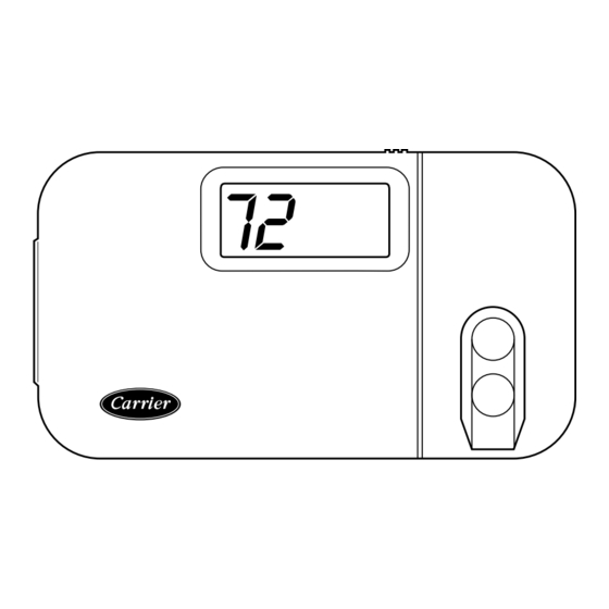
Thermidistat™ Control
HEIGHT (IN.)
4-3/8
Fig. 1-Thermidistat Control
INSTALLATION CONSIDERATIONS
POWER
Note that this control does not require batteries and is not "power
stealing." It does require 24vac (R and C terminals) of the
low-voltage transformer to be connected to it for proper operation.
It will not operate without these 2 connections.
MODELS
There is a single programmable/non-programmable model for all
applications. It can be configured for AC or HP, 1- or 2-speed
compressor, and for dual fuel installations, allowing it to be used
in place of all Carrier thermostats.
HUMIDIFY EQUIPMENT AND CONNECTIONS
.
The humidify output connects directly to 24vac operated humidi-
fiers. No other connection or interlock is required. Any of several
installer-selectable operating modes are available.
DO NOT connect Furnace HUM terminal directly to
Thermidistat HUM terminal. This will bypass furnace safety
controls. See Low Voltage Wiring Daigrams and notes for
proper connection.
DEHUMIDIFY EQUIPMENT AND CONNECTIONS
The dehumidify output connects to the dehumidify input on
variable-speed furnaces and fan coils. Additional dehumidification
is done by controlling the compressor. A variety of operating
modes are available.
OUTDOOR TEMPERATURE SENSOR
Optimum performance is obtained when an outdoor temperature
sensor is used with the Thermidistat Control. Plan installation so
that 2 wires can be run from Thermidistat Control to an outdoor
location, preferably on the north side of the house or refer to
Installation Instructions included with the outdoor temperature
sensor for simplified connection. Sensor can be mounted to
outdoor unit and existing control wires may be used for its
connection. Details are provided in sensor instructions.
Form TSTAT-23SI
WIDTH (IN.)
DEPTH (IN.)
7-3/8
1-3/8
Pg 1
8-99
Replaces: TSTAT-19SI
A98426
Advertisement
Table of Contents

Related Manuals for Carrier Thermidistat


Summary of Contents for Carrier Thermidistat
-
Page 1: Table Of Contents
Optimum performance is obtained when an outdoor temperature sensor is used with the Thermidistat Control. Plan installation so that 2 wires can be run from Thermidistat Control to an outdoor location, preferably on the north side of the house or refer to Installation Instructions included with the outdoor temperature sensor for simplified connection. -
Page 2: Installation
Step 2—Set DIP Switches There is a 4 section DIP switch within the Thermidistat Control which must be properly set by the installer. It is easiest to set these 4 switches before the Thermidistat Control is mounted to the wall, so STOP and complete the following steps: 1. -
Page 3: Configuration Options — Selection
Unlike conventional anticipators, this setting is not determined by current draw. There is no need to measure, know, or compensate for current draw. There is also no droop with this Thermidistat Control. Regardless of setting and number of stages, both heating and cooling will control to their respective set points. - Page 4 3. Use up and down buttons to move between F and C on large display. 4. Press SET TIME/TEMP button again to flash upper small display for selection of another option, or press END to exit configuration mode. Option 4—Fan (G) On With W This selection determines whether fan (G) output is to be ON or OFF when any W (furnace or strip heat) output is ON.
- Page 5 Option 12—Defrost Heat Select This option allows installer to select the amount of heat provided by Thermidistat Control during a heat pump defrost cycle. This can be very helpful in maintaining a comfortable leaving air tempera- ture during defrost. The Thermidistat Control senses when defrost is in progress by monitoring voltage placed on the O line by the heat pump while defrosting.
- Page 6 (4 minutes typical, 10 minutes maximum). An additional feature of Thermidistat Control defrost is that it always allows defrost cycle to run to completion. The Thermidistat Control leaves the Y output on as long as outdoor unit holds voltage on the O line, even if it is satisfied.
-
Page 7: System Start-Up And Checkout
To match these redefined but- tons, a new keypad label, included with the Thermidistat, must be placed over the original keypad label. Fig. 2 shows both the original keypad label and the non-programmable keypad label. -
Page 8: Final Settings
For further information on temperature selection and program- ming, refer to Homeowner’s Guide. The various humidity control features of the Thermidistat Control are explained below. They are grouped into 2 sections: humidifi- cation and dehumidification. At the end of each section, instruc- tions on how to select each feature are given. -
Page 9: Dehumidification
50 to 90 percent relative humidity. When actual humidity is higher than set point, a dehumidification demand exists. The Thermidistat Control responds by activating its dehu- midify output. It may also control the compressor and blower, depending on equipment type and dehumidify selection choice. -
Page 10: Vacation
Thermidistat Control and furnace. The relay coil is connected between DHUM output on the Thermidistat Control and COM terminal on the furnace control. Its normally closed contact is connected between R and DEHUM terminals on the furnace control, where the DEHUM terminal is a spade lug located next to the transformer secondary connections. -
Page 11: Vacation Dehumidification
"--" in place of room temperature Thermidistat Control cannot properly read room temperature. Replace Thermidistat Control. "E3" or "--" in place of outdoor temperature Thermidistat Control cannot properly read outdoor temperature. Check outdoor sensor and its wiring. "E4" or "E5"... -
Page 12: Thermidistat Control Configuration Record.12
Manufacturer reserves the right to discontinue, or change at any time, specifications or designs without notice and without incurring obligations. Book 1 PC 101 Catalog No. 03TS-TA17 Tab misc. misc. Thermidistat Model No. B) Mode Settings ____ Hold (On or Off) ____ Mode (Off, Heat, Cool, Auto, Eheat) ____ Heating Set Point Value...
Need help?
Do you have a question about the Thermidistat and is the answer not in the manual?
Questions and answers