Advertisement
Quick Links
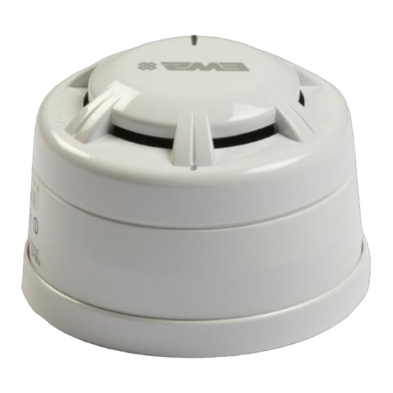
Wireless Detector
Installation Guide
1 Pre installation
Installation must conform to applicable local installation
!
codes and should only be installed by a fully trained
competent person.
Ensure that the device is installed as per the site survey.
The use of a non-metallic spacer should be considered if
mounting the device on to a metal surface.
Do NOT Press the Log On button on a pre-programmed
device, as this will cause communication with the Control
Panel to be lost. Should this happen, delete the device from
the system and add it back on.
This device contains electronics that may be susceptible to
damage from Electrostatic Discharge (ESD). Take appropriate
precautions when handling electronic boards.
3 Fix mounting plate
Remove
the
mounting
ANTICLOCKWISE, to release it from the mounting plate.
Use both mounting holes to ensure a firm fixing.
Use suitable fasteners and fixings.
5 Optional device locking
To lock the wireless module
into the mounting plate, insert
a 1.5 mm allen key into the
allen
key
slot
and
clockwise as shown.
The
detector
can
also
locked
into
the
module. To do so, prior to
refitting the detector, remove
the cut out (shaded) section
as shown.
©2021 EMS Ltd. All rights reserved
Example shown:
www.emsgroup.co.uk
Radio Detector Base
FCX-177-001
IDENT
PRESS HERE TO
LOG ON
FCX-170-001
plate
by
turning
the
63 mm
turn
be
wireless
Part no
FCX-170-001
FCX-174-001
FCX-175-001
FCX-176-001
FCX-177-001
See the Specification section for compliance information.
2 Components
1
1
Dust cover
4
Battery retaining plate
4 Power device
device
Unclip the battery retaining plate from the wireless module.
When fitting / replacing batteries; observe correct polarity,
using only specified batteries.
Connect the power jumper across the PIN header.
Once powered, reassemble the device.
6 Device unlocking
To unlock the detector from
the wireless module, insert a
1.5mm allen key and lever the
allen key towards the outside
of the device whilst turning the
detector
release as shown.
To unlock the wireless module
from
the
insert a 1.5 mm allen key and
turn anticlockwise to release
as shown.
Page 1 of 2
Product description
Wireless Detector Base Only
Multisensor Smoke Detector Only
Heat A1R Detector Only
Heat CS Detector Only
Optical Smoke Detector Only
3
2
2
3
Detector
5
Mounting plate
SIZE AA
(pins unlinked)
SIZE AA
SIZE AA
SIZE AA
SIZE AA
(both pins linked)
SIZE AA
anticlockwise
to
mounting
plate,
TSD044-99 Iss 15 23/11/2021
CPR
[3]
[4]
[1]
[1]
[2]
4
5
Wireless module
device
unpowered
device
powered
AJM
Advertisement

Related Manuals for EMS FireCell FCX-170-001


Summary of Contents for EMS FireCell FCX-170-001
- Page 1 To do so, prior to insert a 1.5 mm allen key and refitting the detector, remove turn anticlockwise to release the cut out (shaded) section as shown. as shown. ©2021 EMS Ltd. All rights reserved Page 1 of 2 TSD044-99 Iss 15 23/11/2021...
- Page 2 113 x 76 mm (with smoke detector) 113 x 81 mm (with heat detector) European Union EMS declares that this device is in compliance with 113 x 87 mm (with multisensor detector) directives Directive 2014/53/EU. The full text of the EU...
Need help?
Do you have a question about the FireCell FCX-170-001 and is the answer not in the manual?
Questions and answers