Table of Contents
Advertisement
Available languages
Available languages
Quick Links
Advertisement
Table of Contents

Related Manuals for EC POWER BW8+


Summary of Contents for EC POWER BW8+
- Page 1 K 0 0 0 1 0 5 M A N U A L 01DOC1175-02 VERSION 1.0 2021...
- Page 2 VAT DK19228509 (DE) Technische Änderungen, Designabweichungen und Irrtümer vorbehalten. Alle Bilder dienen ausschließlich der Veranschaulichung und können abweichen. (EN) Subject to technical changes, design modifications and errors. All pictures shown are for illustrative purposes only. © by EC POWER A/S.
-
Page 3: Table Of Contents
K000105 BW8+ INHALTSVERZEICHNIS K O M P O N E N T E N & W E R K Z E U G ....................4 KOMPONENTEN ................................................... -
Page 4: K O M P O N E N T E N & W E R K Z E U G
K000105 BW8+ K O M P O N E N T E N & W E R K Z E U G B W 8 + ( B R E N N W E R T - A B G A S W Ä R M E TA U S C H E R ) Einschließlich Sicherheitszulassungskomponenten Anschluss zum Abgasrohr Ø80 mm (Toleranz + 0,3 mm / - 0,0 mm) laut EN 14471 T120 M1 (120 ˚C /1.500 Pascal) -
Page 5: Masse & Anschlüsse
K000105 BW8+ M A S S E & A N S C H L Ü S S E Rücklaufanschluss 1¼“ RG (Rücklauf vom BW8+ zum Q-Wärmeverteiler) Rücklaufanschluss 1¼“ RG (Rücklauf vom Wärmespeicher/ Verbrauchernetz zum BW8+) Abgasanschluss D80 mm Kondensatanschluss ½“ RG 320 mm 178 mm 272 mm... -
Page 6: Montage
K000105 BW8+ M O N TA G E BEI DER INSTALLATION UND/ODER WARTUNG DES PLATTENWÄRMETAU- SCHERS IST GEEIGNETE SCHUTZKLEIDUNG, D.H. SCHUTZBRILLE, HANDSCHU- HE UND SCHUHE, ZU TRAGEN. BITTE BEACHTEN SIE: ■ GEFÜLLTE PLATTENWÄRMETAUSCHER KÖNNEN SCHWER SEIN. ■ PLATTENWÄRMETAUSCHER KÖNNEN BEIM BETRIEB BEI HOHEN TEMPERA- TUREN HEISS SEIN. -
Page 7: Frontabdeckung
K000105 BW8+ F R O N TA B D E C K U N G ■ Frontabdeckung (7) Platzieren Sie anschließend die auf dem Isoliermaterial am Plattenwärmetauscher und befestigen Sie die Frontabdeckung unten mit 2 x Bolzen M8x16 (8), 4 x Scheibe M8 (9) 4 x Muttern M8 (10). -
Page 8: Panzerschläuche
K000105 BW8+ PA N Z E R S C H L ÄU C H E ■ Panzerschläu- Legen Sie jeweils eine Dichtung in die Überwurfmuttern der che (15). Panzerschläuche mit Isolierung (15) ■ Schrauben Sie die beiden an den An- schlüssen des Plattenwärmetauschers fest und verbinden Sie diese mit den Q-Wärmeverteiler und dem Wärmespeicher/Verbrauchernetz. -
Page 9: Elektrische Einbindung
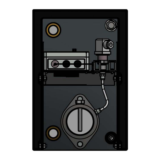
K000105 BW8+ E L E K T R I S C H E E I N B I N D U N G ELEKTRONIKRAUM (POWER UNIT) Druck - 350 mbar (interner Abgaswärmetauscher) Druckwächter Abgasdruck Kabelklemme wird im Elektronikraum der Power Unit platziert. Kabeldurchführung (Power Unit) Sicherheitsbox am BW8+... -
Page 10: Fehlerbehebung
K000105 BW8+ F E H L E R B E H E B U N G Anlagen-Stopp auf Grund eines Fehlers im Abgassystem: Code 62 – Hoher Abgasdruck F E H L E R U R S A C H E : Zu hoher Druck vor dem internen Abgaswärmetauscher (Druckwächter (130 ■... -
Page 11: Reinigung
K000105 BW8+ R E I N I G U N G Der normalerweise hohe Turbulenzgrad des Plattenwärmetauschers führt zu einem Selbstreinigungseffekt in den Flüssigkeitskanälen, der die Verschmut- zung und die Ansammlung von Verunreinigungen verringert, wodurch die Wärmeübertragungskapazität erheblich verringert und der Druckabfall er- höht werden kann. -
Page 12: Components & Tools
K000105 BW8+ C O M P O N E N T S & T O O L S B W 8 + ( E X T E R N A L E X H A U S T H E AT E X C H A N G E R ) Including certified safety components Connection to the exhaust pipe Ø80 mm (tolerance +0,3 mm/-0,0 mm) accord- ing to EN 14471 T120 M1 (120 ˚C/1,500 Pascal). -
Page 13: Dimensions & Connections
K000105 BW8+ D I M E N S I O N S & C O N N E C T I O N S Return connection 1¼“ G (return from the BW8+ to the Q-Heat Distributor) Return connection 1¼“ G (return from the Storage Tank to the BW8+) Exhaust gas connection D80 mm Condensate connection ½“... -
Page 14: Assembly
K000105 BW8+ A S S E M B LY SUITABLE PROTECTIVE CLOTHING I.E. GOGGLES, GLOVES AND SHOES SHALL BE WORN DURING INSTALLING AND/OR MAINTENANCE OF PLATE HEAT EXCHANGERS. PLEASE BE AWARE OF: ■ FILLED PLATE HEAT EXCHANGERS MIGHT BE HEAVY, ■... -
Page 15: Front Cover
K000105 BW8+ F R O N T CO V E R ■ front cover (7) Place the over the insulating material onto the plate heat 2 x Bolt M8x16 (8), exchanger and fasten the front cover at the bottom with 4 x washers M8 (9) 4 x nuts M8 (10). -
Page 16: Flexible Reinforced Hoses
K000105 BW8+ F L E X I B L E R E I N F O R C E D H O S E S ■ reinforced hoses (15). Place one gasket onto each of the union nuts on the reinforced hoses with insulation (15) ■... -
Page 17: Electrical Connection
K000105 BW8+ E L E C T R I C A L C O N N E C T I O N ELECTRONICS COMPARTMENT (POWER UNIT) Pressure - 350 mbar (internal exhaust heat exchanger) Pressure switch Exhaust gas pressure Cable clamp is placed in the electronics compart- ment of the power unit Cable bushing... -
Page 18: Troubleshooting
K000105 BW8+ T R O U B L E S H O O T I N G System stop due to an error in the exhaust system: Code 62 – High exhaust pressure. E R R O R C A U S E : Excessive pressure before the internal exhaust heat exchanger (pressure ■... -
Page 19: Cleaning
K000105 BW8+ C L E A N I N G The normally high degree of turbulence in the plate heat exchanger gives a self-cleaning effect in the liquid channels, which reduces fouling and the build-up of contamination, which can seriously reduce heat transfer capacity and increase pressure drop. - Page 20 K 0 0 0 1 0 5 M A N U A L 01DOC1175-02 08/2021...
Need help?
Do you have a question about the BW8+ and is the answer not in the manual?
Questions and answers