Diamond Atomix DH Series User Manual
Spiral mixer
Hide thumbs
Also See for Atomix DH Series:
- User manual (43 pages) ,
- User manual (43 pages) ,
- User manual (43 pages)
Table of Contents
Advertisement
Available languages
Available languages
Quick Links
Advertisement
Chapters
Table of Contents

Related Manuals for Diamond Atomix DH Series


Summary of Contents for Diamond Atomix DH Series
- Page 1 11/2019 Mod: DH42/T2V(230/3) Production code: TS38DZ...
- Page 2 USER’S MANUAL Atomix Line Serie DH SPIRAL MIXER...
-
Page 3: Table Of Contents
INDEX 1.0 INFORMAZIONI GENERALI ....................... 5 1.1 Garanzia ............................5 1.2 Caratteristiche della macchina ......................5 1.4 Schemi elettrici ..........................9 1.5 Zona occupata dall'operatore ......................9 1.6 Avvertenze generali per la sicurezza ..................9; 10 1.7 Avvertenze per la sicurezza ......................10 2.0 Avvertenze, descrizione e criteri di sicurezza ................ - Page 4 8.5 Esploso TSA25-38-44 ........................29 8.6 Lista componenti TC5-44 ......................24 8.6 Lista componenti TS5-44 ....................... 32 8.7 Lista componenti TS12A-44A ......................33 8.8 Schema elettrico impianto monofase per TC5-8 ................24 8.8 Schema elettrico impianto monofase per TS5-8 Monofase ............36 8.9 Schema elettrico Impianto Trifase per TS5-8.................
- Page 5 0.0 PREFACE This manual is directed towards those who install, operate and maintain the machine so that they can take advantage of the characteristics of the product in the best way. It is important that this manual is kept and remains with the machine if it is moved or if ownership changes so that it can be consulted under all circumstances and therefore the necessary information is available to operate it within safe conditions.
- Page 6 three-phase 2 speeds Electric circuit fed by a cable to the network to which are connected at low tension (24V) the control devices to start, to stop, and of the safety devices. Among these l'internal blocking of the moving parts activated by the movement of the mobile protection of the pan. The machine with raising top and removable bowl, is functionally identical to the machine with fixed top and bowl.
- Page 7 Fig. 1 TS5; TS8 TS12; TS18; TS25; TS38; TS44 TSA12; TSA18; TSA25; TSA38; TSA44...
- Page 8 1.3 TECHNICAL SPECIFICATIONS Model Kneading Flour Bowl Bowl Motor Volt Dimensions Weight capacity capacity volume dim. Power A C B TS5M 237X160 0.37 230/50/1 540X260X520 TS5T 237X160 0.37 400/50/3 540X260X520 TS5D 237X160 0.3/0.45 400/50/3 540X260X520 TS8M 260X200 0.37 230/50/1 550X270X553 TS8T 260X200 0.37...
- Page 9 1.5 OPERATING AREA In the normal working conditions and to have the best exploration of the potentiality of the machine, the operator needs the area represented in Fig. 2. Fig. 2 mt 2 mt 1,5...
- Page 10 1.6 GENERAL SAFETY INSTRUCTIONS Although the machine is built in conformity to the required security rules regarding electrical, mechanical and hygienic regulation it can be dangerous if: Used in case and condition different to those described by the manufacturer. ...
- Page 11 not any parts damaged, all the parts have been set up correctly and all the conditions that could influence the regular functioning of the machine are in working order. Repairing the machine by qualified personnel. The repairs can only be done by qualified people, using original spare parts.
- Page 12 2 INSTALLATION OF THE MACHINE 2.1 ENVIRONMENTAL CONDITIONS OF INSTALLATION SITE The environmental conditions in which the machine must be installed must follow these characteristics: Free of humidity Water and heat sources at safe distance from the machine Adequate ventilation and lighting corresponding to hygiene and security regulations following the existing laws Well-dimensioned flat and stable surface for easier cleaning.
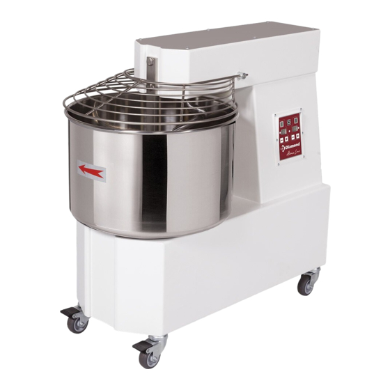
- Page 13 2.3 ELECTRICAL CONNECTIONS The connection type Y of the machine with the electric network is made by means of an operation cable, which is provided with a plug only in the single-phase model. As far as the three-phase machines are concerned it is necessary to put together the cable and a normalized and polarized plug (the distinction between phase and neutral must be unequivocal), and verify that the rotation way of the bowl is the same indicated by the arrow on the bowl.
- Page 14 3 CONTROL AND SAFETY DEVICES The machine is equipped with the following control and , safety devices: 3.1 CONTROL DEVICES 3.1.1 MACHINE TS5-8 Fig. 5b Fig. 5 FIG.5: Single-Phase Machine FIG. 5B: Two speeds Machine A – Green START button B –...
- Page 15 3.1.2 MACHINE TS12-44 SINGLE-PHASE, THREE-PHASE AND TWO SPEEDS (FIG.6- Position Description Fig. 6 A/A1 Start Button for 1 speed Start Button for 2 speed Red STOP button Led signalling the operation in 1 speed Led signalling the operation in 2 speed Led signalling connection to the mains/Led status Fig.
- Page 16 ATTENTION The single safety device are efficient when: On raising the protetion I (PICT. 8) the machine stops. On raising the top (by means of the check pin M and/or taking off bowl the machine does not start. ...
- Page 17 · Restart the machine and verify if the bowl is rotating the right way. Start the machine without using it, let it on for about one minute and verify that it is functioning perfectly. Fig. 9 3.3.2 TS12-44, TS12A-44A MODELS Single-phase and three-phase machines (Fig.6): Single-phase models TS12M-44M, TS12AM-44AM and three-phase models TS12T-44T, TS12AT-44AT allow the setting of time working with a timer.
- Page 18 3.3.3 THREE-PHASE 2 SPEEDS AUTOMATIC (FIG.7): TS12D-44D, TS12AD-44AD models allow the automatic control of working time in 1 and 2 speed using the timers relating to 1 and 2 speed. It is possible to exclude the functioning of the timer in 1 and 2 speed.
- Page 19 Fig. 9...
- Page 20 4 USE OF THE MACHINE Before starting work make sure that the machine is perfectly clean in particular, the surfaces of bowl, the spiral and of the central column that have contact with the food products. If necessary clean them following indications at 5.1.
- Page 21 Fig. 10-11 4.4 REPOSITIONING OF THE BOWL AND TOP Once the cleaning is done, put the bowl back on, and make sure that the four pins underneath (PICT. 11) are correctly fixed in the four holes K of the machine; then block the bowl rotating clockwise the disk O. Put the top down pushing it downwards (PICT.
- Page 22 5 MAINTENANCE WARNING Before effecting any kind of maintenance or cleaning you must take out the plug. In any case of malfunction or damage of the machine you must apply for authorized assistance from the manufacturer WARNING Qualified personnel only must perform maintenance. 5.1 CLEANING The cleaning must be done every time the machine has been used following all the rules to prevent malfunctioning of the machine and for hygienic purposes.
- Page 23 Fig. 14-15 5.3 GREASING OF CHAINS WARNING Qualified personnel only must perform greasing of chains After unscrewing the fixing screws, take away the upper P and the back V panels, put on the chains S-T (PICT. 15-16) a reasonable amount of proper grease, sufficient to lubricate all the links of the chain.
- Page 24 5.4 POSSIBLE ANOMALIES ANOMALY CAUSE SOLUTION The machine does not Lack of energy in the Check the general switch, the plug, the start tap and the feeding cable power grid The Emergency stop button in Rotate the button following the blocked direction of the arrow The protection grid and/or the top...
- Page 25 Belgique Chaussée de Vilvorde 92, 1120 Bruxelles Téléphone : 02 420 26 26 N° de TVA : BE 0436.355.290 fax : +32 (0)2 420 67 66 info@diamond-eu.com www.diamond-eu.com...
- Page 26 Manuale Utente Atomix Line Serie DH IMPASTATRICE A SPIRALE...
- Page 27 INDICE 1.0 INFORMAZIONI GENERALI ..................................4 1.1 Garanzia ....................................... 4 1.2 Caratteristiche della macchina ................................4 1.4 Schemi elettrici ....................................7 1.5 Zona occupata dall'operatore ................................7 1.6 Avvertenze generali per la sicurezza ..............................8 1.7 Avvertenze per la sicurezza ................................. 8 2.0 INSTALLAZIONE E MESSA IN FUNZIONE ..............................
- Page 28 7.1 Parti di ricambio ..................................... 17 8.0 Allegati ........................................ 17 8.1 Esploso TS5-8 ....................................18 8.2 Esploso TS12-18 ....................................19 8.3 Esploso TS25-38-44 .................................... 20 8.4 Esploso TSA12-18 ....................................21 8.5 Esploso TSA25-38-44 ..................................22 8.6 Lista componenti TS5-44 ................................... 25 8.7 Lista componenti TS12A-44A ................................
-
Page 29: Informazioni Generali
0.0 Prefazione Questo manuale è diretto a tutti coloro che sono preposti all'installazione, l'uso e la manutenzione delle impastatrici in modo che possano sfruttare nel migliore dei modi le caratteristiche del prodotto. È importante che questo manuale venga conservato e segua la macchina in tutti i suoi eventuali trasferimenti, cambio di proprietà compreso, allo scopo di poter essere consultato all'occorrenza e disporre quindi delle informazioni necessarie per operare in condizioni di sicurezza. - Page 30 Fig. 1 TS5; TS8 TS12; TS18; TS25; TS38; TS44 TSA12; TSA18; TSA25; TSA38; TSA44...
- Page 31 1.3 Caratteristiche tecniche Potenza motore Volt Dimensioni mm Peso Modello Capacità d' impasto Capacità farina Volume vasca Dim. vasca TS5M 237X160 0.37 230/50/1 540X260X520 TS5T 237X160 0.37 400/50/3 540X260X520 TS5D 237X160 0.3/0.45 400/50/3 540X260X520 TS8M 260X200 0.37 230/50/1 550X270X553 TS8T 260X200 0.37 400/50/3...
-
Page 32: Schemi Elettrici
1.4 Schemi elettrici Per gli schemi elettrici riferirsi al paragrafo 8.8-8.13 1.5 Zona occupata dall'operatore In normali condizioni operative e per lo sfruttamento ottimale delle potenzialità della macchina, l'operatore necessita dell'area rappresentata nella Fig. 2. Fig. 2 mt 2 mt 1,5... -
Page 33: Avvertenze Generali Per La Sicurezza
1.6 Avvertenze generali per la sicurezza La macchina pur essendo conforme ai requisiti di sicurezza previsti dalle norme di riferimento, elettriche, meccaniche, igieniche, può costituire pericolo: · Se usata per scopi e condizioni diverse da quelle previste dal costruttore. · Per manomissione delle protezioni e dei dispositivi di sicurezza. ·... -
Page 34: Installazione E Messa In Funzione
2.0 INSTALLAZIONE E MESSA IN FUNZIONE 2.1 Prescrizioni a carico dell'utente Le condizioni ambientali del luogo dove viene installata la macchina devono avere le seguenti caratteristiche: · Essere prive di umidità. · Fonti idriche e di calore adeguatamente distanti. · Ventilazione ed illuminazione adeguata e rispondenti alle norme igieniche e di sicurezza previste dalle leggi vigenti. Il pavimento deve essere piano e compatto onde favorire una pulizia accurata. -
Page 35: Dispositivi Di Comando E Sicurezza
Fig. 3 Fig. 4 3.0 DISPOSITIVI DI COMANDO E SICUREZZA Le macchine sono dotate dei seguenti dispositivi di comando e di sicurezza: 3.1 DISPOSITIVI DI COMANDO Macchine modello TS5-8 con alimentazione monofase o trifase (Fig. 5-5b): Posizione Descrizione Fig. 5 Pulsante verde Avviamento Pulsante rosso Arresto Commutatore selettore delle velocità... -
Page 36: Dispositivi Di Sicurezza
Macchine modello TS12-44 con alimentazione monofase, trifase e trifase due velocità automatica (Fig.6-7): Posizione Descrizione Fig. 6 Pulsante Avviamento prima velocità A/A1 Pulsante Avviamento seconda velocità Pulsante rosso Arresto Led indicatore funzionamento in prima velocità Led indicatore funzionamento in seconda velocità Led presenza rete / indicatore di stato Fig. -
Page 37: Verifica Funzionale
Fig. 8 Prima di avviare la macchina (messa in funzione-uso) abbassare completamente la testata P e la protezione I (FIG. 9). Nelle versioni apribili, verificare che la vasca sia correttamente inserita e bloccata dal disco O e che la testa in posizion e orizzontale sia bloccata dalle maniglie M e M1, le quali devono essere completamente serrate. - Page 38 Funzionamento con esclusione del timer: AVVIAMENTO: premere il pulsante A per avviare sia la vasca che la spirale. ARRESTO: premere il pulsante B, per arrestare sia la vasca che la spirale. Durante il funzionamento la spia luminosa indicata in fig,6 dalla lettera R è di colore verde, mentre se si solleva il riparo mobile, lettera I fig.8-9, la spia diventa di colore rosso, indicando l'intervento del sistema di sicurezza della macchina.
-
Page 39: Uso
Fig. 9 4.0 USO Prima d'iniziare ogni ciclo di lavoro accertarsi che la macchina sia perfettamente pulita in particolare, le superfici di contatto della vasca, della spirale e del piantone centrale, che vanno trattati con detersivi compatibili con i prodotti alimentari. -
Page 40: Riposizionamento Della Vasca E Della Testa
Fig. 10-11 4.2.2 Riposizionamento della vasca e della testa Ultimata l'operazione di pulizia, rimontare la vasca assicurandosi che i 4 perni sottostanti (FIG. 11) vengano correttamente inseriti all'interno dei fori K della macchina, bloccare la vasca ruotando in senso antiorario il disco O. Riposizionare orizzontalmente la testa premendola progressivamente verso il basso (FIG. - Page 41 ATTENZIONE Si raccomanda di non utilizzare in nessun caso prodotti chimici non alimentari abrasivi o corrosivi. Evitare nel modo più assoluto di usare getti d'acqua, utensili vari, mezzi ruvidi o abrasivi quali pagliette in acciaio, spugne ecc. che possano danneggiare le superfici ed in particolare compromettere la sicurezza sotto il profilo igienico. Per conservare sia l'efficienza delle prestazioni che la sicurezza della macchine è...
-
Page 42: Possibili Anomalie
5.3 Ingrassaggio catene ATTENZIONE. La manutenzione della macchina deve essere eseguita solo da operatori specializzati. Dopo aver svitato le viti di fissaggio, togliere i pannelli superiore P e posteriore V, depositare all'interno delle catene S-T (FIG. 15) una ragionevole quantità di grasso idoneo o sufficiente ad assicurare la lubrificazione di tutte le maglie delle catene. Ad operazione completata rimontare i due pannelli e riavvitare le viti. - Page 43 Belgique Chaussée de Vilvorde 92, 1120 Bruxelles Téléphone : 02 420 26 26 N° de TVA : BE 0436.355.290 fax : +32 (0)2 420 67 66 info@diamond-eu.com www.diamond-eu.com...
Need help?
Do you have a question about the Atomix DH Series and is the answer not in the manual?
Questions and answers