Advertisement
Quick Links
Advertisement

Subscribe to Our Youtube Channel
Related Manuals for Eltorque QT Series


Summary of Contents for Eltorque QT Series
- Page 1 ID 2021, rev 3.2, January 14, 2022 User Manual QT series generation 2.5...
- Page 2 Added Dual Power option 14.01.2022 Copyright © 2022, Eltorque AS This document is submitted in confidence and contains proprietary information which shall not be reproduced or transferred to others for the purpose, tender or any other intensions without written permission of Eltorque AS...
- Page 3 Dual CANopen interface connection -------------------------------------- 42 4.8.4 Digital interface connection --------------------------------------------------- 43 4.8.5 Analog interface connections ------------------------------------------------- 44 Chapter 5 Operation ........................45 Manual operation ....................45 User Manual QT series generation 2.5, ID 2021, rev 3.2, January 14, 2022 Page 3 of 88...
- Page 4 Ordering Information and accessories ................. 81 Torque and Screw Recommendations ................83 Eltorque torque recommendations ..............83 Mounting screws and lubrication ..............83 Page 4 of 88 User Manual QT series generation 2.5, ID 2021, rev 3.2, January 14, 2022...
- Page 5 Table of Contents M4 screws on communication interface box ..........84 Earthing Methods in Maritime Installations ..............85 User Manual QT series generation 2.5, ID 2021, rev 3.2, January 14, 2022 Page 5 of 88...
- Page 7 Eltorque actuators have a proven track record of maintenance-free operation with 15+ years operation. Figure 1: System overview example User Manual QT series generation 2.5, ID 2021, rev 3.2, January 14, 2022 Page 7 of 88...
- Page 8 Power has Analog/Digital and CAN interfaces. See Product description in chapter 10.1 See article number keying for configuration details in Chapter 12 Ordering Information and Page 8 of 88 User Manual QT series generation 2.5, ID 2021, rev 3.2, January 14, 2022...
- Page 9 Option for CANOnly see Chapter 9 on page 59. • Option for Dual Power see Chapter 10 on page 61. • Option for Failsafe operation see Chapter 11 on page 63. User Manual QT series generation 2.5, ID 2021, rev 3.2, January 14, 2022 Page 9 of 88...
- Page 10 A warning is used to draw attention to information of very high importance, for example, to avoid injuries to personnel. This User Manual QT series generation 2.5 are related to the following documentation: Page 10 of 88 User Manual QT series generation 2.5, ID 2021, rev 3.2, January 14, 2022...
- Page 11 Eltorque document ID 1691 The information contained in this document is subject to change without prior notice. Eltorque AS shall not be liable for errors contained herein or for incidental or consequential damages about the furnishing, performance, or use of this document. It is the customer’s responsibility to verify that he has the latest revision available by checking the document area of www.eltorque.com.
- Page 12 A valve is a device that controls the flow of materials (gases, fluidized Valve solids, slurries, or liquids) by opening, closing, or partially obstructing various passageways. Page 12 of 88 User Manual QT series generation 2.5, ID 2021, rev 3.2, January 14, 2022...
- Page 13 Chapter 12 gives ordering information. The reader group for this chapter is technical support and management personnel. User Manual QT series generation 2.5, ID 2021, rev 3.2, January 14, 2022 Page 13 of 88...
- Page 14 Appendix B includes the document “Earthing Methodology in Maritime Installations” The reader group for this chapter is installation personnel, technical support and technical management personnel. Page 14 of 88 User Manual QT series generation 2.5, ID 2021, rev 3.2, January 14, 2022...
- Page 15 All batteries and electronic equipment may contain substances harmful to the environment. Therefore, after removing used equipment, return them for disposal according to local governmental guidelines. User Manual QT series generation 2.5, ID 2021, rev 3.2, January 14, 2022 Page 15 of 88...
- Page 16 This page is left intentionally blank. Page 16 of 88 User Manual QT series generation 2.5, ID 2021, rev 3.2, January 14, 2022...
- Page 17 The QT-series is the most sold product series in the Eltorque portfolio. The QT series generation 2.5 consists of five products with maximum torque ranging from 70 to 1000Nm. The QT series is equipped with a position sensor that gives correct position feedback, even after a power outage. All products can be manually operated utilizing a fixed hand wheel located under the cover on top of the actuator, without external tools.
- Page 18 At a system level, the PLC, PC or Controller must be compliant with Eltorque communication protocol according to Eltorque System Integrators Manual CANopen Interface. Page 18 of 88 User Manual QT series generation 2.5, ID 2021, rev 3.2, January 14, 2022...
- Page 19 E-VCS. The E-VCS includes an HMI interface on the cabinet and can also support an HMI interface on the main control level. User Manual QT series generation 2.5, ID 2021, rev 3.2, January 14, 2022 Page 19 of 88...
- Page 20 Eltorque communication protocol according to Eltorque System Integrators Manual CANopen Interface. Figure 6: Eltorque actuator dual CAN loop connected to Integrated Automation Control System (IAS or ICS) Page 20 of 88 User Manual QT series generation 2.5, ID 2021, rev 3.2, January 14, 2022...
- Page 21 Bottom view Top view Figure 7: QT70, QT250 and QT400 external construction Bottom view Top view Figure 8: QT800 and QT1000 external construction User Manual QT series generation 2.5, ID 2021, rev 3.2, January 14, 2022 Page 21 of 88...
- Page 22 IP rating, type approval, the production serial number, and the production date. In the red rectangle is a computer readable QR code containing a serial number. Page 22 of 88 User Manual QT series generation 2.5, ID 2021, rev 3.2, January 14, 2022...
- Page 23 X2, analog terminal X3, placement of label for X5 terminal and Terminal Block Connections. The last label is placed on the separation plate. Figure 11: Label overview inside the communication interface box User Manual QT series generation 2.5, ID 2021, rev 3.2, January 14, 2022 Page 23 of 88...
- Page 24 More details are found in Chapter 8 Dual CAN Option, Chapter 10 Dual Power Option ,and Chapter 11 Failsafe Option. Page 24 of 88 User Manual QT series generation 2.5, ID 2021, rev 3.2, January 14, 2022...
- Page 25 2 K of the coolant temperature.” (IEC 60034-1, chapter 4.2.2) Eltorque actuators may be used in classes A and B – 10 000 cycles per lifetime. Endurance is defined according to EN 15714-2, chapter 4.1 and Annex A.
- Page 26 70 mΩ/ 3ft 3.37 in Max 100 m/3ft 3.37 in Normally equivalent to 0.5–1.5 mm /0.02 – 0.06 in Cable length (affects Maximum 500 m/1650 ft. communication speed) Page 26 of 88 User Manual QT series generation 2.5, ID 2021, rev 3.2, January 14, 2022...
- Page 27 (see Table 7 for details). Table 7: Relay outputs – digital interfaces Function Value Rated voltage 48V AC/VDC Max. switching voltage 48V AC/VDC Rated current User Manual QT series generation 2.5, ID 2021, rev 3.2, January 14, 2022 Page 27 of 88...
- Page 28 Further description of the Hybrid Marine Cable is found in the Hybrid Marine Cable datasheet, Eltorque document ID 1982. The datasheet is available on www.eltorque.com – Products – System components. Page 28 of 88 User Manual QT series generation 2.5, ID 2021, rev 3.2, January 14, 2022...
- Page 29 An upside-down hanging position should be avoided. Figure 15: QT70, QT250 and QT400 dimensions Figure 16: QT800 and QT1000 dimensions User Manual QT series generation 2.5, ID 2021, rev 3.2, January 14, 2022 Page 29 of 88...
- Page 30 200 mm/7.9 in. Figure 17: QT70, QT250 and QT400 Space requirements for installation, service and manual operation - side view Page 30 of 88 User Manual QT series generation 2.5, ID 2021, rev 3.2, January 14, 2022...
- Page 31 Figure 18: QT70, QT250 and QT400 Space requirements for installation, service and manual operation – top view Figure 19: QT800 and QT1000 Space requirements for installation, service and manual operation – side view User Manual QT series generation 2.5, ID 2021, rev 3.2, January 14, 2022 Page 31 of 88...
- Page 32 QT800 only has room for one. The type of reducer to be used depends on the valve type - please contact your Eltorque representative or Eltorque support for further details. Page 32 of 88 User Manual QT series generation 2.5, ID 2021, rev 3.2, January 14, 2022...
- Page 33 Be aware that the MAST of the valve needs to be verified to prevent damage to the stem. Eltorque can assist in selecting the correct actuator size for the valve. For the QT-series, the closing time is configurable within a predesigned interval.
- Page 34 For screw dimensions, see Figure 23 and Figure 24. Tighten fastening screws to the specified torque. See Table 16: Screw torque on page 83. Page 34 of 88 User Manual QT series generation 2.5, ID 2021, rev 3.2, January 14, 2022...
- Page 35 The actuator provides fastening holes of different dimensions to facilitate mounting on different types of valves. Figure 23: QT70, QT250 and QT400 Valve flange fastening holes User Manual QT series generation 2.5, ID 2021, rev 3.2, January 14, 2022 Page 35 of 88...
- Page 36 Using ferrules is not recommended. If ferrules are used the sole responsibility for a correct installation lies on the installing party. Page 36 of 88 User Manual QT series generation 2.5, ID 2021, rev 3.2, January 14, 2022...
- Page 37 Eltorque’s IP certification may be voided if the instructions of the glands are not followed. Support the cable to prevent it from twisting Note! User Manual QT series generation 2.5, ID 2021, rev 3.2, January 14, 2022 Page 37 of 88...
- Page 38 0.25 - 2.5 mm²/0.0098 – 0.0984 in If ferrules are used the sole responsibility for a correct installation lies on the installing party. Page 38 of 88 User Manual QT series generation 2.5, ID 2021, rev 3.2, January 14, 2022...
- Page 39 The Norwegian Electrical Safety Directorate. Failing to do so may void the warranty. Exception: Field equipment shall be grounded through the supply cable. User Manual QT series generation 2.5, ID 2021, rev 3.2, January 14, 2022 Page 39 of 88...
- Page 40 . The cable must be compliant to the ISO 11898-2 standard. If ferrules are used the sole responsibility for a correct installation lies on the installing party. Page 40 of 88 User Manual QT series generation 2.5, ID 2021, rev 3.2, January 14, 2022...
- Page 41 An example of a CAN installation for n+2 nodes with a CANopen controller is shown in Figure 30. Figure 30: Example of CANopen network connections User Manual QT series generation 2.5, ID 2021, rev 3.2, January 14, 2022 Page 41 of 88...
- Page 42 Figure 32 shows a typical dual CAN network with termination for n+2 nodes and two CAN controllers. Figure 32: Dual CAN network connection For information on how to set the node ID, please consult the Eltorque E3C Manual. Page 42 of 88...
- Page 43 Figure 33: Digital connection interface terminals The digital interface can be used in various control circuits. Two examples are shown in Figure 34. Figure 34: Digital interface options User Manual QT series generation 2.5, ID 2021, rev 3.2, January 14, 2022 Page 43 of 88...
- Page 44 Figure 35: Analog connection interface terminals An example of using the analog interface is shown in Figure 36 Figure 36: Example of 4-20 mA analog control circuit. Page 44 of 88 User Manual QT series generation 2.5, ID 2021, rev 3.2, January 14, 2022...
- Page 45 3. When the manual operation is completed, refit the hand-wheel cover by pressing it down until it stops against the actuator’s top cover. User Manual QT series generation 2.5, ID 2021, rev 3.2, January 14, 2022 Page 45 of 88...
- Page 46 Valve percent position is a [0%, 100%] value. A value of 0% corresponds to the CLOSED position, while a value of 100% corresponds to the OPEN Page 46 of 88 User Manual QT series generation 2.5, ID 2021, rev 3.2, January 14, 2022...
- Page 47 Reset conditions: A new position command (OPEN, CLOSE, GOTO, STOP). The motor can then run again, given that the trigger conditions for the alarm have disappeared. User Manual QT series generation 2.5, ID 2021, rev 3.2, January 14, 2022 Page 47 of 88...
- Page 48 The actuator with bus interface does not Manual. respond to control signals. The actuator responds normally when tested with E3C. Bus control system is not wired or configured correctly. Page 48 of 88 User Manual QT series generation 2.5, ID 2021, rev 3.2, January 14, 2022...
- Page 49 3.8 After replacement of interface, the actuator Configuration. does not operate correctly. Contact the local Eltorque agent for support if required. User Manual QT series generation 2.5, ID 2021, rev 3.2, January 14, 2022 Page 49 of 88...
- Page 50 This page is left intentionally blank. Page 50 of 88 User Manual QT series generation 2.5, ID 2021, rev 3.2, January 14, 2022...
- Page 51 MEK ( methyl ethyl ketone). Caution! Do not use high pressure power washer directly on the actuators as the product is not IP69K rated. User Manual QT series generation 2.5, ID 2021, rev 3.2, January 14, 2022 Page 51 of 88...
- Page 52 This page is left intentionally blank. Page 52 of 88 User Manual QT series generation 2.5, ID 2021, rev 3.2, January 14, 2022...
- Page 53 “System Integrators Manual CANopen interface” ID 1691. For more technical information about the Eltorque CANopen communication, refer to the “System Integrators Manual CANopen interface” ID 1691. User Manual QT series generation 2.5, ID 2021, rev 3.2, January 14, 2022 Page 53 of 88...
- Page 54 Alarm. The following failure scenarios trigger an alarm: • Manual emergency operation • Valve position out of defined operation area • Valve blocked Page 54 of 88 User Manual QT series generation 2.5, ID 2021, rev 3.2, January 14, 2022...
- Page 55 12 mA/ 50%, the valve position is in the range of 45-55%). If higher accuracy is needed, please consider a CAN bus interface with an accuracy of +/- 0.5% instead. User Manual QT series generation 2.5, ID 2021, rev 3.2, January 14, 2022 Page 55 of 88...
- Page 56 This page is left intentionally blank. Page 56 of 88 User Manual QT series generation 2.5, ID 2021, rev 3.2, January 14, 2022...
- Page 57 Due to its design, some latency will occur in each node. This results in a Note! lower number of nodes per loop compared to a standard CAN node. User Manual QT series generation 2.5, ID 2021, rev 3.2, January 14, 2022 Page 57 of 88...
- Page 58 This page is left intentionally blank. Page 58 of 88 User Manual QT series generation 2.5, ID 2021, rev 3.2, January 14, 2022...
- Page 59 The CANOnly can be configured as Single CAN or Dual CAN interface. This configuration shall be used in the situation where a customer doesn’t require digital and/or analog interfaces. User Manual QT series generation 2.5, ID 2021, rev 3.2, January 14, 2022 Page 59 of 88...
- Page 60 This page is left intentionally blank. Page 60 of 88 User Manual QT series generation 2.5, ID 2021, rev 3.2, January 14, 2022...
- Page 61 From the junction box, a star connection is established to power the individual actuator. Figure 42 An example of an installation with Dual Power actuators User Manual QT series generation 2.5, ID 2021, rev 3.2, January 14, 2022 Page 61 of 88...
- Page 62 Strip conductor to 11 mm insert the conductor in the splicing connector and secure it. For connecting the main power supply follow the description in chapter 4.6 Power supply connection Page 62 of 88 User Manual QT series generation 2.5, ID 2021, rev 3.2, January 14, 2022...
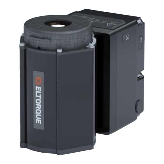
- Page 63 Chapter 8 Dual CAN on page 57. The failsafe actuator supports CAN, digital and analog interfaces. Note! Figure 43: Actuator with Failsafe option User Manual QT series generation 2.5, ID 2021, rev 3.2, January 14, 2022 Page 63 of 88...
- Page 64 This chapter covers Eltorque’s input for planning. Eltorque can also quote assistance for both the planning activities and the installation activities if requested. Page 64 of 88 User Manual QT series generation 2.5, ID 2021, rev 3.2, January 14, 2022...
- Page 65 Install the actuator with the battery mounted in the module of the installed product. This installation method can be divided into two options: User Manual QT series generation 2.5, ID 2021, rev 3.2, January 14, 2022 Page 65 of 88...
- Page 66 The purpose of this discharge test is to establish the real battery capacity (SOH) safely. Please refer to section 11.8.1 Battery discharge and charge on page 74 for instructions on how to perform this test. Page 66 of 88 User Manual QT series generation 2.5, ID 2021, rev 3.2, January 14, 2022...
- Page 67 There must be a minimum of 150 mm/5.90 in space above and to the sides of the actuator to accommodate room for installation, operation and service. User Manual QT series generation 2.5, ID 2021, rev 3.2, January 14, 2022 Page 67 of 88...
- Page 68 The failsafe actuator has several configurable parameters. The tables below show the parameters that trigger the failsafe protocol and other important parameters necessary to adjust for correct error behavior. Page 68 of 88 User Manual QT series generation 2.5, ID 2021, rev 3.2, January 14, 2022...
- Page 69 See Chapter 4 Mounting and Installation on page 34 on how to connect the external power and signal cables to the communication interface unit. User Manual QT series generation 2.5, ID 2021, rev 3.2, January 14, 2022 Page 69 of 88...
- Page 70 Remove the nuts by turning them counterclockwise. Place the nuts in a secure location. Required equipment: • 4mm Hexagon Key Figure 48: QT Series generation 2.5 – opening the failsafe actuator Installation Page 70 of 88 User Manual QT series generation 2.5, ID 2021, rev 3.2, January 14, 2022...
- Page 71 30 seconds before attaching again. It is not possible to access this state from IAS/E3C. In normal state, the actuator works as a standard QT Series generation 2.5 and can receive commands from IAS/E3C. However, if the failsafe state or service state has been activated, the normal state is only resumed if failsafe or service is cleared from the IAS or E3C.
- Page 72 IAS/E3C. The state must be reset from the IAS/E3C. For information on how to operate the handwheel, please see Manual operation on page 45. Page 72 of 88 User Manual QT series generation 2.5, ID 2021, rev 3.2, January 14, 2022...
- Page 73 The battery must be recharged, see 11.8.1 below. 230 VAC power has been lost for >12 days while in service mode (not deep sleep) User Manual QT series generation 2.5, ID 2021, rev 3.2, January 14, 2022 Page 73 of 88...
- Page 74 Turn off the power going to all actuators that the battery change procedure is going to be performed on. (Be aware of failsafe triggers for the rest of the loop.) Page 74 of 88 User Manual QT series generation 2.5, ID 2021, rev 3.2, January 14, 2022...
- Page 75 Make sure to not drop the interface, or to let it hang by the cables. Disconnect the battery cable connector marked by a yellow circle in the illustration. User Manual QT series generation 2.5, ID 2021, rev 3.2, January 14, 2022 Page 75 of 88...
- Page 76 The screws are circled red in the illustration. Required equipment: − 2,5mm Hexagon Key. Page 76 of 88 User Manual QT series generation 2.5, ID 2021, rev 3.2, January 14, 2022...
- Page 77 Disable service mode from the actuator control system. Make sure that the actuator state indicator light is green on all actuators that have received a new battery. User Manual QT series generation 2.5, ID 2021, rev 3.2, January 14, 2022 Page 77 of 88...
- Page 78 Remove the interface as shown in the illustration. Make sure to not drop the interface, or to let it hang by the cables. Page 78 of 88 User Manual QT series generation 2.5, ID 2021, rev 3.2, January 14, 2022...
- Page 79 The cable with the blue sleeve connects to the cable with the blue sleeve, and the cable with the black sleeve connects to the PCB. User Manual QT series generation 2.5, ID 2021, rev 3.2, January 14, 2022 Page 79 of 88...
- Page 80 Disable service mode from the actuator control system. Make sure that the actuator state indicator light is green on all actuators that have received a new battery. Page 80 of 88 User Manual QT series generation 2.5, ID 2021, rev 3.2, January 14, 2022...
- Page 81 250.120.5 – an QT250 in Single CAN interface and self-lock configuration. 800.120.5BRH – an QT800 in Failsafe, Dual CAN interface and self-lock configuration. Available accessories er listed in the Table 15. User Manual QT series generation 2.5, ID 2021, rev 3.2, January 14, 2022 Page 81 of 88...
- Page 82 Config. Cable QT-series series actuators 35036 QT Series Actuator label Label 60 x 80 mm Premium Extra For availability contact your sales representant. Page 82 of 88 User Manual QT series generation 2.5, ID 2021, rev 3.2, January 14, 2022...
- Page 83 The thread-locks main purpose in this application is to serve as a barrier, preventing seawater from acting as a catalyst between bolts and threads in the actuator base. User Manual QT series generation 2.5, ID 2021, rev 3.2, January 14, 2022 Page 83 of 88...
- Page 84 Tighten the screws in the sequence indicated in the figure below. • Tighten fasteners with low rpms, without interruptions. • Apply only light pressure. Figure 50: Tightening sequence for M4 screws Page 84 of 88 User Manual QT series generation 2.5, ID 2021, rev 3.2, January 14, 2022...
- Page 85 2. The outer screen must be cut and not connected to the housing for the connection between two actuators on different power loops. A shrink tube shall be used to cover all bare wires. User Manual QT series generation 2.5, ID 2021, rev 3.2, January 14, 2022 Page 85 of 88...
- Page 86 Page 86 of 88 User Manual QT series generation 2.5, ID 2021, rev 3.2, January 14, 2022...
- Page 88 Phone: +47 7485 5520 info@eltorque.no...
Need help?
Do you have a question about the QT Series and is the answer not in the manual?
Questions and answers