Table of Contents
Advertisement
Advertisement
Table of Contents

Related Manuals for Eltorque QT50


Summary of Contents for Eltorque QT50
- Page 1 Doc ID 1321 version 2.0 Sept. 2018 User Manual QT50...
- Page 2 Table 1: Document history for User Manual QT50 Document ID Version Author Changes Approved by Date 1321 June 2017 1321 Nov. 2017 1321 Added info on harness Feb. 2018 1321 New layout and structure Sept. 2018 Copyright © 2018, Eltorque AS...
-
Page 3: Table Of Contents
Mounting the actuator on the valve ..............31 Mounting procedure QT50 ................. 31 Valve flange fastening holes ................32 Cable connection overview ................33 Cable glands ...................... 37 Power supply connection ................... 37 User Manual QT50 Doc ID 1321 version 2.0 Sept. 2018 Page 3 of 62... - Page 4 Torque and Screw Recommendations ..........57 A. 1. Eltorque torque recommendations ..............57 A. 2. Mounting screws and lubrication ............... 57 Earthing Methods in Maritime Installations ........59 Page 4 of 62 User Manual QT50 Doc ID 1321 version 2.0 Sept. 2018...
-
Page 5: Introduction
MT-series ideal for manifold actuation. The Eltorque actuators are fully electric and can be connected in series. They offer a plug and play solution with low installation costs and high level of security. -
Page 6: Description
Table of Contents Description The QT50 described in this user manual is the smallest actuator in the Eltorque QT-series. This series is characterized by their quarter-turn movement and low energy consumption along with their small footprint. They are suited for butterfly, ball and other quarter-turn valves. -
Page 7: Area Of Use
Introduction Area of use Eltorque actuators are an ideal choice in a wide range of Maritime and Onshore systems including, but not limited to: Cargo handling Bilge and ballast Tank gauging SPS system Anti-heeling systems ... -
Page 8: Related Documentation
Disclaimer The information contained in this document is subject to change without prior notice. Eltorque AS shall not be liable for errors contained herein or for incidental or consequential damages about the furnishing, performance, or use of this document. It is the customer’s responsibility to verify that he has the latest revision available by checking the document area of www.eltorque.no... - Page 9 Hazardous area Products described in this manual are not suitable for use in hazardous areas. Eltorque can deliver actuators for use in such areas if required. Please contact your local representative for further details. Human Machine Interface.
- Page 10 As an example, most butterfly valves comprise four screw holes for the flange integration and a square stem for valve operation. Within range Definition of position. The outgoing shaft is within the defined position area. Page 10 of 62 User Manual QT50 Doc ID 1321 version 2.0 Sept. 2018...
-
Page 11: About This User Manual
About this user manual This user manual describes the guidelines for installation, setup and operation of QT50 in a valve control system. The valid products for this manual are listed in Table 2: Product overview on page 6. Chapter 1 introduces the product and this manual. - Page 12 Table of Contents This page is left intentionally blank Page 12 of 62 User Manual QT50 Doc ID 1321 version 2.0 Sept. 2018...
-
Page 13: Hse Information
Disposal and waste handling All batteries and electronic equipment may contain substances harmful to the environment. After removing used equipment, return them for disposal according to local governmental guidelines. User Manual QT50 Doc ID 1321 version 2.0 Sept. 2018 Page 13 of 62... - Page 14 HSE Information This page is left intentionally blank Page 14 of 62 User Manual QT50 Doc ID 1321 version 2.0 Sept. 2018...
-
Page 15: Product Description
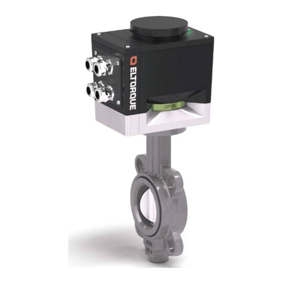
QT50 actuator The QT50 actuator is suitable for valves with torque requirements of 10 - 50 Nm, it can be delivered with CANopen, Analog and Digital communication. The actuator is designed to be operational during a temporary submerged situation, see details for housing in Table 5: System performance parameters for QT50 actuators on page 17. -
Page 16: Actuator Control System Examples
Marine Cable. This cable can be used with the CANopen communication interface. In addition, QT50 actuators support Digital and Analog connections. Figure 3 below shows Eltorque actuators that are connected to a cabinet with Eltorque valve control system (E-VCS). In this example, pump starters are also connected to the E-VCS. -
Page 17: Technical Specification
Product Description Figure 4: Eltorque actuator loop connected to Integrated Automation Control System (IAS or ICS) Technical specification Table 5: System performance parameters for QT50 actuators Feature Value Torque options 10,20,30,40 or 50 Nm Closing time options 0 - 90° movement 5, 8 or 15 sec. - Page 18 Cover of hand-wheel mechanical damage and foreign objects. The actuator must not be lifted by the top cover. The QT50 is equipped with a mechanical self-locking device that locks Self-lock the valve to the target position when the actuator movement command completed.
-
Page 19: Actuator Components
The harness connects directly to the interface boards and are easily pulled out in order to make connections, see Figure 6 for more details. User Manual QT50 Doc ID 1321 version 2.0 Sept. 2018 Page 19 of 62... - Page 20 Product Description Figure 6: Connection harness (with CANopen connector) In older versions of the QT50 the connections must be done directly on the connection board. This is described in version 1.9 of this manual, (document ID 1321 v. 1.9). The QT50 can be delivered with the following interfaces.
-
Page 21: Labelling
The cabling specifications depend on the type of communication interface to be used. The QT50 has four threaded M20 holes for cable glands. When ordering it is important to consider factors like cable type and size, as the cable glands have a limited cable entry range. -
Page 22: Storage
Power consumption The power consumption varies depending on whether the actuator is in standby mode or is running, see Table 5: System performance parameters for QT50 actuators on page 17. Inrush current after loss of power might be high. It is therefore recommended to design the circuit in accordance with information given in chapter 7.1. -
Page 23: Endurance
(IEC 60034-1, chapter 4.2.2) Endurance QT50 actuators may be used classes A and B – 10 000 cycles per lifetime. Endurance is defined according to EN 15714-2, chapter 4.1 and Annex A. For classes A and B - ON/OFF operation and inching/positioning, endurance defines the minimum number of cycles to be endured per life time, where "one... - Page 24 Figure 8: CANopen bus network Eltorque recommends a maximum of 80 nodes on 500 m/1660 ft. cable. Note! The cable between the nodes can be maximum 500m with the Eltorque Hybrid Note! Marine Cable. For other lengths check with your local Eltorque representative.
-
Page 25: Installations With Eltorque Hybrid Marine Cable
Figure 9: Bus connection of actuators The Eltorque Hybrid Marine Cable combines signal and power cable in a hybrid cable with maritime type approval. The cable can only be used for installations User Manual QT50 Doc ID 1321 version 2.0 Sept. 2018... -
Page 26: Orientation
Product Description with CANopen for the QT50 actuator. When this cable is used, only two cable glands are required, see Chapter 8 Ordering Information and Recommended Spare Parts. Figure 10: Hybrid Marine Cable Further description of the Hybrid Marine Cable is found in the Hybrid Marine Cable datasheet, Eltorque document ID 1982. -
Page 27: Space Requirements
In front of actuator where you access the communication interface connections, there should be at least 200 mm /7.87 in. User Manual QT50 Doc ID 1321 version 2.0 Sept. 2018 Page 27 of 62... - Page 28 Product Description Figure 12: QT50 Space requirements for installation, service and manual operation Page 28 of 62 User Manual QT50 Doc ID 1321 version 2.0 Sept. 2018...
-
Page 29: Mounting
There are various adapters available, but the two most common ones are the square reducer and the flange + stem adapter. For the QT50, the majority of valves require an adapter plate. The required plate can be found in table 10 below. -
Page 30: Torque Considerations For Valve And Actuator
Closing time For the QT50 the closing time is configurable within a predesigned interval. The opening and closing profiles are shown in Table 5: System performance parameters for QT50 actuators on page 17. -
Page 31: Mounting And Installation Instructions
31. Insert the fastening screws and use washers according to specifications. For screw dimensions see Figure 15: QT50 Valve flange fastening holes on page 32 to verify correct length bolts for your valve. An overview of typical length are given in table 10, page 29 Adapter plate and screws. -
Page 32: Valve Flange Fastening Holes
Valve flange fastening holes The actuator provides fastening holes of different dimension to facilitate mounting on different types of valves. Figure 15: QT50 Valve flange fastening holes Page 32 of 62 User Manual QT50 Doc ID 1321 version 2.0 Sept. 2018... -
Page 33: Cable Connection Overview
Using ferrules is not recommended. If ferrules are used the sole responsibility for a correct installation lies on the installing party. User Manual QT50 Doc ID 1321 version 2.0 Sept. 2018 Page 33 of 62... - Page 34 Figure 16: Hatch front view Note! On older versions of the QT50 the screws may not be attached to the hatch. Be careful not to lose them. When removing the lid, take care not to lose the gasket in the hatch.
- Page 35 11. Replace the hatch, taking care to position the gasket correctly. 12. Fasten the hatch and tighten the fastening screws, torque 1.8 Nm. Figure 17: CANopen harness User Manual QT50 Doc ID 1321 version 2.0 Sept. 2018 Page 35 of 62...
- Page 36 Mounting and Installation Instructions Figure 18: Digital/analog harness Page 36 of 62 User Manual QT50 Doc ID 1321 version 2.0 Sept. 2018...
-
Page 37: Cable Glands
Mounting and Installation Instructions Cable glands For trouble-free operation, it is important to install the glands and cable correctly. Eltorque’s IP certification may be voided if the instructions of the glands are not followed. Note! Support the cable to prevent it from twisting 1. -
Page 38: Grounding (Earthing)
All bare metal wires, screens or others not covered by the terminal shall be thoroughly covered in a shrink tube to avoid unintended contact between wires, housing or similar. Page 38 of 62 User Manual QT50 Doc ID 1321 version 2.0 Sept. 2018... -
Page 39: Communication Connection Interfaces
For information on how to set the node ID, please consult the Eltorque E3C Manual. User Manual QT50 Doc ID 1321 version 2.0 Sept. 2018... - Page 40 Refer to Appendix B Earthing Methods in Maritime Installations on page 59 for information on connection of screen for the last actuator in the loop (actuator N) Page 40 of 62 User Manual QT50 Doc ID 1321 version 2.0 Sept. 2018...
-
Page 41: Digital Interface Connection
Digital outputs are passive and need external power supply for operation of equipment. Figure 25: Digital connection interface terminals The digital interface can be used in various control circuits as shown below: User Manual QT50 Doc ID 1321 version 2.0 Sept. 2018 Page 41 of 62... -
Page 42: Analog Interface Connections
Analog interface connections Specifications for IOs are given in chapter 3.9.5, table 7. Caution! Analog input is damaged by incorrect polarity Figure 27: Analog connection interface terminals Page 42 of 62 User Manual QT50 Doc ID 1321 version 2.0 Sept. 2018... - Page 43 Mounting and Installation Instructions Figure 28: Example of 4-20 mA analog control circuit. User Manual QT50 Doc ID 1321 version 2.0 Sept. 2018 Page 43 of 62...
-
Page 44: Operation
Mounting and Installation Instructions This page is left intentionally blank Page 44 of 62 User Manual QT50 Doc ID 1321 version 2.0 Sept. 2018... -
Page 45: Manual Operation
Figure 29: Manual operation. 3. When the manual operation is completed, refit the hand-wheel cover by pressing it down until it stops against the actuator’s top cover. User Manual QT50 Doc ID 1321 version 2.0 Sept. 2018 Page 45 of 62... -
Page 46: Error Alarms And Error Handling
Note! To ensure a trouble free commissioning of the systems, it is important to install the products according to regulations and Eltorque Guidelines. Failing to do so may result in unwanted system behavior. GENERAL alarm ... -
Page 47: Temperature Alarm
Troubleshooting The Eltorque actuator is a robust maintenance free product, but you might encounter some issues with the unit. Below is a list of the most common issues that may occur and how to solve them. If you still have problems, please contact Eltorque support for further help. - Page 48 Manually operate the actuator to the (position error on fieldbus) proper closed position and set new closed position with E3C or fieldbus. If leakage persist, please check valve seat face. Page 48 of 62 User Manual QT50 Doc ID 1321 version 2.0 Sept. 2018...
-
Page 49: Maintenance
Maintenance The QT50 actuators are in principle maintenance-free. All bearings and gears are lifetime lubricated and components are designed to last throughout the actuator’s lifetime. It is however recommended that the actuator is inspected regularly to reveal any damages caused by for example mechanical impact or corrosion. - Page 50 Maintenance This page is left intentionally blank Page 50 of 62 User Manual QT50 Doc ID 1321 version 2.0 Sept. 2018...
-
Page 51: Technical Details
20A (Figure 35). Eltorque recommends having a skilled electrical engineer calculate the appropriate number of actuators on a specific loop or UPS. Eltorque can also assist with some experience data on request. -
Page 52: Canopen Interface
The actuator stops and sets ALARM status if OPEN signal is activated during a CLOSE command, or CLOSE signal is activated during an OPEN command. CLOSE signal and OPEN signal (outputs) ALARM signal (output) Page 52 of 62 User Manual QT50 Doc ID 1321 version 2.0 Sept. 2018... -
Page 53: Analog Interface
The feedback is polarity sensitive. Both positioning and feedback signals are analog 4-20 mA. The Analog Interface also has a digital Alarm output, which is trigged by failures in both actuator and valve. User Manual QT50 Doc ID 1321 version 2.0 Sept. 2018 Page 53 of 62... - Page 54 12 mA/ 50%, the valve position is in the range of 45-55%). If a higher accuracy is needed, please consider a CANopen interface with accuracy of +/- 0.5% instead. Page 54 of 62 User Manual QT50 Doc ID 1321 version 2.0 Sept. 2018...
-
Page 55: Ordering Information And Recommended Spare Parts
Ordering Information and Recommended Spare Parts For spare parts, not in the list below, please contact your local Eltorque representative. Eltorque can deliver SDoC, MD and AFD. With reference to IMO Resolution MEPC 269(68), SOLAS Reg. II-/3-5 and IACS SC 249 or latest valid revision. - Page 56 QT50 1.0 Hand wheel cover 900.001 Eltorque Configuration cable for QT- Config. Cable QT-series series actuators 10400 Terminal resistor 120ohm Terminal resistor 120ohm 35036 Label reprint Label reprint Page 56 of 62 User Manual QT50 Doc ID 1321 version 2.0 Sept. 2018...
-
Page 57: Torque And Screw Recommendations
The thread-lock’s main purpose in this application is to serve as a barrier, preventing sea-water to act as a catalyst between bolts and threads in the actuator base. User Manual QT50 Doc ID 1321 version 2.0 Sept. 2018 Page 57 of 62... - Page 58 Torque and Screw Recommendations This page is left intentionally blank Page 58 of 62 User Manual QT50 Doc ID 1321 version 2.0 Sept. 2018...
-
Page 59: Earthing Methods In Maritime Installations
2. It is important that the outer screen is cut and not connected to the housing for the connection between two actuators on different power loops. Shrink tube shall be used to cover all bare wires. User Manual QT50 Doc ID 1321 version 2.0 Sept. 2018 Page 59 of 62... - Page 60 Earthing Methods in Maritime Installations Page 60 of 62 User Manual QT50 Doc ID 1321 version 2.0 Sept. 2018...
- Page 61 This page is left intentionally blank...
- Page 62 SWBD: +47 7485 5520 info@eltorque.no...
Need help?
Do you have a question about the QT50 and is the answer not in the manual?
Questions and answers