Table of Contents
Advertisement
Quick Links
Advertisement
Table of Contents

Related Manuals for Troy-Bilt GARDEN WAY 12194


Summary of Contents for Troy-Bilt GARDEN WAY 12194
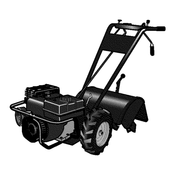
- Page 1 $ 4.50 OWNER’S MANUAL 8HP Model Tiller • Safety • Assembly • Controls SAFETY FIRST! Before operating this equipment, read this • Operation Owner's Manual and the separate manual supplied by the engine manufacturer. • Maintenance • Parts List Model 12194 GARDEN WAY INCORPORATED...
-
Page 2: Table Of Contents
Table of Contents Dear Owner: Thank you for purchasing our product. You now own one SECTION 1: SAFETY ........... of the finest rear-tine rototillers available. It has been Safety Decals ............. designed, engineered and manufactured to give you the SECTION 2: ASSEMBLY ........best possible dependability and performance. -
Page 3: Section 1: Safety
Section Safety SPARK ARRESTER WARNING TO RESIDENTS OF Reverse CALIFORNIA AND SEVERAL OTHER STATES Clutch Control Under California law, and under the laws of several Forward Clutch Wheel Gear other states, you are not permitted to operate an inter- Lever Lever nal combustion engine using hydrocarbon fuels on any forest, brush, hay, grain, or grass covered land;... - Page 4 Section 1: Safety 3. After striking a foreign object, stop the 14. Be aware that the tiller may unexpect- speed. Authorized service shall be sought if engine, remove the wire from the ,spark edly bounce upward or jump backward if a problem exists.
-
Page 5: Safety Decals
Section 1: Safety Safety Decals Refer to the Parts List in this manual for Keep the decals clean and legible at all For your safety and the safety of others, decal locations, part numbers and order- times. Contact your local service dealer or various safety and operational decals are ing instructions. -
Page 6: Section 2: Assembly
Section Assembly HARDWARE PARTS LIST IMPORTANT: Motor oil must be added to WARNING the engine crankcase before the engine is Fig.# Description Qty. To prevent personal injury or property started. Follow the instructions in this Height Adjustment Handle damage, do not start the engine until all Assembly section. -
Page 7: Attach Reverse Clutch Lever
Section 2: Assembly 4. Move the handlebar to align the STEP 3: ATTACH REVERSE 2. Insert a hairpin cotter down through threaded hole in the cross-brace with one the hole in the rod that is located closest CLUTCH LEVER of the four slots in the curved height to the bend (see 4, Figures 2-1 and 2-7) . -
Page 8: Check Transmission Gear Oil Level
Section 2: Assembly STEP 5: CHECK TRANSMISSION NOTE: Do not use automatic transmission fluid or motor oil in the transmission. GEAR OIL LEVEL The transmission was filled with gear oil at (a) Clean area around oil fill hole (L, Figure the factory. -
Page 9: Attach Wheel Gear Lever
Section 2: Assembly STEP 8: ATTACH WHEEL GEAR LEVER For shipping purposes, the wheel gear cable is wrapped around the transmission. Carefully unwrap the cable and attach it as follows: 1. Route the wheel gear cable up the left- side handlebar and insert the lever (S, Figure 2-15) up through the slot in the control panel, labeled WHEEL GEAR. -
Page 10: Section 3: Features & Controls
Section Features and Controls Gear Lever (A, Figure 3-1) into ENGAGE WARNING position when either Forward Clutch Lever Before operating your machine, care- is pulled up against the handlebars. This fully read and understand all safety, is a safety feature designed to prevent the controls and operating instructions in wheels from being in DISENGAGE (free- this Manual, the separate Engine... -
Page 11: Depth Regulator Lever
Section 3: Features and Controls The wheels will rotate in a reverse direc- WARNING tion as long as the lever is held in REVERSE. To stop the wheels and tines, Whenever the handlebar height is release the lever and it will return to changed, the Forward Clutch shift mech- NEUTRAL. -
Page 12: Section 4: Operation
Section Operation Reverse Clutch Control Throttle Lever WARNING Wheel Gear Lever Before operating your machine, carefully Forward Clutch Lever read and understand all safety (Section 1), controls (Section 3) and operating instructions (Section 4) in this Manual, Forward Clutch Lever in the separate Engine Owner’s Manual, Recoil and on the decals on the machine. -
Page 13: Operating Tiller
Section 4: Operation 8. Check behind you to avoid contacting WARNING any obstacles when pulling the starter rope. Place one hand on the fuel tank to Do not push down on the handlebars to stabilize the unit and use the recoil starter try to make the tiller till more deeply. -
Page 14: Changing Belt Range Speeds
Section 4: Operation Stopping the Tiller and Engine NOTE: If the belt is difficult to move, pull on the engine start rope while pushing the 1. To stop the wheels and tines, release belt with your finger (engine drive pulley the Forward Clutch levers or the Reverse will turn as start rope is pulled). -
Page 15: Tilling Tips & Techniques
Section 4: Operation TILLING TIPS & TECHNIQUES Tilling Depths • When cultivating (breaking up surface soil around plants to • This is a CRT (counter-rotating tine) tiller. As the wheels pull destroy weeds, see Figure 4-9), adjust the tines to dig only forward, the tines rotate backward. -
Page 16: Loading And Unloading Tiller
Section 4: Operation TILLING TIPS & TECHNIQUES (cont.) Tilling On Slopes WARNING Read the following recommendations before tilling on slopes: If you must garden on a moderate slope, please follow two very Do not operate the tiller on a slope too steep for safe opera- important guidelines: tion. -
Page 17: Section 5: Maintenance
Section Maintenance A little seepage around a cover or oil seal WARNING is usually not a cause for alarm. However, Before inspecting, cleaning if the oil drips overnight, then immediate servicing the machine, shut off engine, attention is needed—ignoring a leak can wait for all moving parts to come to a result in severe transmission damage. -
Page 18: Engine Oil Service
Section 5: Maintenance WARNING Before inspecting, cleaning or servicing the machine, shut off engine, wait for all moving parts to come to a complete stop, remove ignition key on electric start models, disconnect spark plug wire and move wire away from spark plug. Failure to follow these instructions can result in serious personal injury or property damage. -
Page 19: Throttle Control Adjustment
Section 5: Maintenance WARNING Before inspecting, cleaning or servicing the machine, shut off engine, wait for all moving parts to come to a complete stop, remove ignition key on electric start models, disconnect spark plug wire and move wire away from spark plug. Failure to follow these instructions can result in serious personal injury or property damage. -
Page 20: Checking And Adjusting Tension On Drive Belts
Section 5: Maintenance WARNING Before inspecting, cleaning or servicing the machine, shut off engine, wait for all moving parts to come to a complete stop, remove ignition key on electric start models, disconnect spark plug wire and move wire away from spark plug. Failure to follow these instructions can result in serious personal injury or property damage. - Page 21 Section 5: Maintenance WARNING Before inspecting, cleaning or servicing the machine, shut off engine, wait for all moving parts to come to a complete stop, remove ignition key on electric start models, disconnect spark plug wire and move wire away from spark plug. Failure to follow these instructions can result in serious personal injury or property damage.
-
Page 22: Forward Drive Belt Removal And Installation
Section 5: Maintenance WARNING Before inspecting, cleaning or servicing the machine, shut off engine, wait for all moving parts to come to a complete stop, remove ignition key on electric start models, disconnect spark plug wire and move wire away from spark plug. Failure to follow these instructions can result in serious personal injury or property damage. -
Page 23: Reverse Drive Belt Removal And Installation
Section 5: Maintenance WARNING Before inspecting, cleaning or servicing the machine, shut off engine, wait for all moving parts to come to a complete stop, remove ignition key on electric start models, disconnect spark plug wire and move wire away from spark plug. Failure to follow these instructions can result in serious personal injury or property damage. -
Page 24: Troubleshooting
Section 5: Maintenance WARNING Before inspecting, cleaning or servicing the machine, shut off engine, wait for all moving parts to come to a complete stop, remove ignition key on electric start models, disconnect spark plug wire and move wire away from spark plug. Failure to follow these instructions can result in serious personal injury or property damage. -
Page 25: Parts List
Parts List Model 12194 DRAWING NO. 1 REF. PART REF. PART DESCRIPTION QTY. DESCRIPTION QTY. 1917117 Handlebars (Incl. Refs. 2, 3, 3A & 4) ... 1186208 Hex Nut, #10-32 ........9126 Grip, Handlebar ........9390 Grip, Lever........... 1917537 Decal, Control Panel ......20863 Bail, Forward Clutch (Incl. - Page 26 Parts List Model 12194 DRAWING NO. 2 REF. PART REF. PART DESCRIPTION QTY. DESCRIPTION QTY. 1917118 Hood, Tine (Incl. Hinged Flap and 1113-1 Bushing (spacer)......... Refs. 17, 17A & 17B) ...... 1186231 Hex Nut, 3/8-16........1100243 Lockwasher, 3/8........1916185001 Drag Bar, Depth Regulator ....1916184001 Bracket, Hood &...
- Page 27 Parts List Model 12194 DRAWING NO. 3 REF. PART REF. PART DESCRIPTION QTY. DESCRIPTION QTY. 1916604001 Engine Support Bracket, Left-Side ..9944 Washer, Disc Spring (concave 1916602001 Engine Support Bracket, Right-Side..surface faces forward pulley) ..1916189001 Engine Support Bracket (Pan), Front... 9301 Key, 3/16 sq.
- Page 28 Parts List Model 12194 DRAWING NO. 4 REVERSE CLUTCH CONTROL ROD* * See Drawing No. 1 for handlebar assembly and controls. REF. PART REF. PART DESCRIPTION QTY. DESCRIPTION QTY. 1185506 Hex Lock Nut, 3/8-16 ......20517-01 Forward Link ........1110043 Hex Hd.
- Page 29 Parts List Model 12194 DRAWING NO. 5 REF. PART REF. PART DESCRIPTION QTY. DESCRIPTION QTY. 9621 Oil Seal, Wheel Shaft ......20712 Clutch, Wheel Drive......9511 Retaining Ring, External, Heavy-Duty 20699 Eccentric Shaft ........1166-1 Shim, 1-1/64 I.D., .062 thick ..... A/R 1442 Pin, Eccentric Shaft ......
- Page 30 Parts List Model 12194 DRAWING NO. 6 OPERATOR POSITION TINE SHAFT ENGINE DENOTES CUTTING EDGE OF TINE Drawing No. 7...
- Page 31 Parts List Model 12194 PARTS LIST - DRAWING NO. 6 PARTS LIST - DRAWING NO. 7 REF. PART REF. PART DESCRIPTION QTY. DESCRIPTION QTY. 1100068 Hex Hd. Screw, 3/8-16 x 3/4* ..... 12 1915056 Wheel & Tire Assy., left-side ....1985101 Tine –...
- Page 32 Parts List Model 12194 DRAWING NO. 8 NOTE 1: These screws are a special sealing screw that cannot be used without risking the loss of transmission oil. If these screws are loosened or removed, they must be replaced with new hardware. REF.
- Page 33 Parts List Model 12194 DRAWING NO. 9 REF. PART REF. PART DESCRIPTION QTY. DESCRIPTION QTY. 1714 Bearing, Tapered Roller (with race) ... 9944 Washer, Disc Spring (concave 20718 Spur Gear, Main Drive Shaft....surface faces pulley)...... 9301 Key, 3/16 sq. x 1 ....... 9301 Key, 3/16 sq.
- Page 34 Parts List Model 12194 DRAWING NO. 10 (BUMPER ATTACHMENT) REF. PART REF. PART DESCRIPTION QTY. DESCRIPTION QTY. 1100242 Lockwasher, 5/16, Not Avail. Separately 1916714001 Bumper,Top Section......(order #1915811 hardware kit) ..1904758001 Bumper, Bottom Section ....1186230 Hex Nut, 5/16-18, Not Avail. 1731025 Curved Hd.
- Page 35 Parts List Model 12194 DRAWING NO. 11 (HILLER/FURROWER OPTIONAL ATTACHMENT) HILLER/FURROWER – PART #12579 (Viewed from front of tiller) REF. PART REF. PART DESCRIPTION QTY. DESCRIPTION QTY. 1900771001 Furrower–blade only......9725 Carriage Bolt–blade mounting, 1186098 Carriage Bolt–5/16-18 x 3/4 ....3/8-16 x 1-1/2 .......
-
Page 36: Customer Service Information
CUSTOMER SERVICE INFORMATION Owner Registration Card Customer Service and Technical Service Please fill out and mail the enclosed owner If you have questions or problems with the registration card. The purpose of this card is unit, contact your local dealer or the Factory. to register each unit at the Factory so that we (When calling or writing, provide the can provide you with warranty benefits and...
Need help?
Do you have a question about the GARDEN WAY 12194 and is the answer not in the manual?
Questions and answers
What is the model and serial numbers for the 6.5 HP 12194?
The model number is 12194. The serial number is not provided in the given context.
This answer is automatically generated