Advertisement
Quick Links
sauder.com
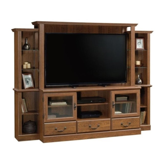
Entertainment/Wall System
Orchard Hills Collection | Model 418653
Need help? Visit Sauder.com to view video assembly tips or chat with a live rep.
Prefer the phone? Call 1-800-523-3987.
Share your journey!
Your center of
attention.
NOTE: THIS INSTRUCTION
BOOKLET CONTAINS IMPORTANT
SAFETY INFORMATION.
PLEASE READ AND KEEP FOR
FUTURE REFERENCE.
English pg 1-42
Français pg 43-47
Español pg 48-52
Lot # 371128
04/27/15
Purchased: __________________
Be sure to give us a ring before
making any returns. 1-800-523-3987
Advertisement

Subscribe to Our Youtube Channel
Summary of Contents for Sauder Orchard Hills 418653
- Page 1 Orchard Hills Collection | Model 418653 NOTE: THIS INSTRUCTION BOOKLET CONTAINS IMPORTANT SAFETY INFORMATION. Need help? Visit Sauder.com to view video assembly tips or chat with a live rep. PLEASE READ AND KEEP FOR FUTURE REFERENCE. Prefer the phone? Call 1-800-523-3987.
- Page 2 • Check the size and weight of your TV. Compare it to the diagram below – before you begin assembly! • This Sauder unit is designed for use with televisions weighing less than 95 pounds. Never use with a TV that weighs more.
- Page 3 RIGHT END (1) LEFT DRAWER SIDE (3) LEFT END (1) DRAWER BACK (2) ADJUSTABLE SHELF (1) LARGE DRAWER BACK (1) SMALL AJDUSTABLE SHELF (2) D701 DRAWER BOTTOM (2) LARGE DRAWER FRONT (1) D968 LARGE DRAWER BOTTOM (1) www.sauder.com/services 418653 Page 3...
- Page 4 While not all parts are labeled, some of the parts will have a label or an inked letter on the edge to help distinguish similar parts from each other. Use this part identifi cation to help identify similar parts. YYYY WWWW XXXX D701 D968 D701 Page 4 418653 www.sauder.com/services...
- Page 5 NAIL - 106 GROMMET CAP - 1 GROMMET - 3 02/ 02 269227 (Refer to step 35 for proper location and application) RUBBER SLEEVE - 36 CAM COVER - 6 SCREW COVER - 4 METAL PIN - 36 www.sauder.com/services 418653 Page 5...
-
Page 6: Table Of Contents
GOLD 9/16" LARGE HEAD SCREW - 16 15S SILVER 5/8" MACHINE SCREW - 6 SILVER 1-1/8" FLAT HEAD SCREW - 12 30S BLACK 1-9/16" FLAT HEAD SCREW - 12 BLACK 1-1/8" MACHINE SCREW - 2 SILVER 2" HEX BOLT - 4 Page 6 418653 www.sauder.com/services... - Page 7 Look for this icon. It means a Step 1 video assembly tip is available at www.sauder.com/services/tips Assemble your unit on a carpeted fl oor or on the å empty carton to avoid scratching your unit or the fl oor. Scan this QR code or go to this address: http://qr.sauder.com/?ID=1332...
- Page 8 SHELVES (R), and BACK MOLDINGS (UU). Then, insert a CAM DOWEL (2F) into each HIDDEN CAM. Do not tighten the HIDDEN CAMS in this step. Arrow (42 used) Arrow Insert the metal end of the CAM DOWEL into the HIDDEN CAM. Arrow Page 8 418653 www.sauder.com/services...
- Page 9 Insert the SPRING CLIPS (38G) into the spaces between å you do something else. the TOP (M) and MOLDINGS (OOand PP). * U.S. Patent No. 5,499,886 å Slide the MOLDINGS (NN, OO, and PP) onto the notched edges. www.sauder.com/services 418653 Page 9...
- Page 10 Insert the SPRING CLIPS (38G) into the spaces between å the TOPS (N and O) and MOLDINGS (BBB and CCC). * U.S. Patent No. 5,499,886 å Slide the MOLDINGS (OO, PP, BBB, and CCC) onto the notched edges. Page 10 418653 www.sauder.com/services...
- Page 11 Slide the POSTS (G, H, and I) onto the notched edges of å the POSTS (E, F, and Z). * U.S. Patent No. 5,499,886 å These edges should be even. These edges should be even. Slide the POSTS (G, H, and I) onto the notched edges. www.sauder.com/services 418653 Page 11...
- Page 12 Fasten the TV SHELF MOLDING (QQ) to the TV SHELF (P). å Use four SILVER 1-1/8" FLAT HEAD SCREWS (10S). Remember: Righty tighty. Lefty loosey. SILVER 1-1/8" FLAT HEAD SCREW (4 used in this step) Curved edge Curved edge Page 12 418653 www.sauder.com/services...
- Page 13 MOLDINGS (ZZ, AAA, DDD, and EEE). NOTE: The MOLDINGS (DDD and EEE) have holes drilled å completely through. Use your hammer to tap the MOLDING CONNECTORS (19F) into the notches in the MOLDINGS. Flat end Flat end www.sauder.com/services 418653 Page 13...
-
Page 14: Gold 5/16" Flat Head Screw
LEFTS (35DB) to the UPRIGHTS (K and L) and ENDS (BB and CC). Use eight GOLD 5/16" FLAT HEAD SCREWS (3S). GOLD 5/16" FLAT HEAD SCREW (8 used in this step) Finished edge Roller end Finished edge Roller end Page 14 418653 www.sauder.com/services... - Page 15 Fasten the CABINET RIGHT (35DA) and CABINET å LEFT (35DB) to the UPRIGHTS (K and L). Use four GOLD 5/16" FLAT HEAD SCREWS (3S). Finished edge GOLD 5/16" FLAT HEAD SCREW Roller end (4 used in this step) Finished edge Roller end www.sauder.com/services 418653 Page 15...
- Page 16 Tighten Risk of damage or Arrow injury. HIDDEN CAMS must be completely Arrow Maximum tightened. HIDDEN 210 degrees CAMS that are not completely tightened may loosen, and parts may separate. To Minimum completely tighten: 190 degrees Page 16 418653 www.sauder.com/services...
- Page 17 Fasten the BACK (Y) to the TOP (M). Tighten two å HIDDEN CAMS. Maximum Arrow 210 degrees Minimum 190 degrees S u r f a c H I D D E N i t h o www.sauder.com/services 418653 Page 17...
- Page 18 Fasten the TV SHELF (P) to the BACK (Y), POSTS (E å and F), and MOLDINGS (UU). Use six BLACK 1-7/8" FLAT Minimum HEAD SCREWS (2S). 190 degrees BLACK 1-7/8" FLAT HEAD SCREW (6 used in this step) Page 18 418653 www.sauder.com/services...
- Page 19 Fasten the TOPS (N and O) to the POSTS (E, F, G, and H). å Do not stand the unit upright without the Use four BLACK 1-7/8" FLAT HEAD SCREWS (2S). BACK fastened. The unit may collapse. BLACK 1-7/8" FLAT HEAD SCREW (4 used in this step) www.sauder.com/services 418653 Page 19...
- Page 20 Fasten the MOLDINGS (FFF) to the TOPS (N and O). Use å BACK fastened. The unit may collapse. four BLACK 9/16" LARGE HEAD SCREWS (1S). BLACK 9/16" LARGE HEAD SCREW (8 used in this step) (4 used) Page 20 418653 www.sauder.com/services...
- Page 21 (4 used) Notched edge i t h Notched edge f a c S u r D E N H I D i t h o f a c S u r D E N H I D www.sauder.com/services 418653 Page 21...
- Page 22 Step 16 Slide the END MOLDINGS (VV) onto the notched edges å of the ENDS (A and B). * U.S. Patent No. 5,499,886 å Slide the MOLDINGS (VV) onto the notched edges. Curved edge Page 22 418653 www.sauder.com/services...
- Page 23 Tighten eight HIDDEN CAMS. Minimum Fasten the SHELVES (S and T) to the ENDS (A and B). 190 degrees å Use four BLACK 1-7/8" FLAT HEAD SCREWS (2S). BLACK 1-7/8" FLAT HEAD SCREW (4 used in this step) www.sauder.com/services 418653 Page 23...
-
Page 24: Silver 1-1/8" Flat Head Screw
Step 18 Fasten the MOLDINGS (ZZ, AAA, DDD, and EEE) to the å SHELVES (S and T). Use eight SILVER 1-1/8" FLAT HEAD SCREWS (10S). Curved edge SILVER 1-1/8" FLAT HEAD SCREW (8 used in this step) Page 24 418653 www.sauder.com/services... - Page 25 Fasten the UPRIGHTS (K and L) to the TV SHELF (P). å Tighten four HIDDEN CAMS. Minimum 190 degrees Finished edge fi n i s h r f a BLACK 1-7/8" FLAT HEAD SCREW (4 used in this step) www.sauder.com/services 418653 Page 25...
- Page 26 HIDDEN CAMS These holes S u r must be here. f a c w i t h H I D D E N Surface with HIDDEN CAMS BLACK 1-7/8" FLAT HEAD SCREW (4 used in this step) Page 26 418653 www.sauder.com/services...
- Page 27 H I D Surface with HIDDEN CAMS i t h o f a c S u r D E N H I D BLACK 1-7/8" FLAT HEAD SCREW (4 used in this step) Surface with HIDDEN CAMS www.sauder.com/services 418653 Page 27...
- Page 28 Fasten the ENDS (BB and CC) to the TV SHELF (P). å Minimum Tighten four HIDDEN CAMS. 190 degrees Fasten the ENDS (C and D) to the MOLDINGS (DDD å and EEE). Tighten four HIDDEN CAMS. Page 28 418653 www.sauder.com/services...
- Page 29 Slide the END MOLDINGS (WW) onto the notched edges å of the ENDS (C and D). Don't worry. It isn't Rome. This can be built * U.S. Patent No. 5,499,886 å in a day. Slide the MOLDINGS (WW) onto the notched edges. Curved edge www.sauder.com/services 418653 Page 29...
- Page 30 Fasten thirteen ANGLE BRACKETS (4G) to the å ENDS (C, D, BB, and CC) and BOTTOMS (U and V). Use thirteen BLACK 9/16" LARGE HEAD SCREWS (1S). BLACK 9/16" LARGE HEAD SCREW (13 used in this step) (13 used) Page 30 418653 www.sauder.com/services...
- Page 31 Fasten the BASES (RR, SS, and TT) to the ENDS (C, D, BB, å and CC) and BOTTOMS (U and V). Use thirteen BLACK 9/16" LARGE HEAD SCREWS (1S). BLACK 9/16" LARGE HEAD SCREW (13 used in this step) www.sauder.com/services 418653 Page 31...
- Page 32 SCREWS (1S) through the ANGLE BRACKETS and into the BOTTOM. Fasten the SUPPORTS (XX) to the BRACES (YY). Use å four BLACK 9/16" LARGE HEAD SCREWS (1S). BLACK 9/16" LARGE HEAD SCREW (24 used in this step) Page 32 418653 www.sauder.com/services...
- Page 33 BACK. Carefully cut out the holes needed. BLACK 9/16" LARGE HEAD SCREW (20 used in this step) YYYY WWWW XXXX YYYY XXXX These holes must line up over the SHELVES (P, S, and T). Overlap the BACKS. www.sauder.com/services 418653 Page 33...
- Page 34 Step Step 28 Fasten the HINGES (6H) to the DOORS (AA). Use eight å GOLD 9/16" LARGE HEAD SCREWS (5S). GOLD 9/16" LARGE HEAD SCREW (8 used in this step) Page 34 418653 www.sauder.com/services...
-
Page 35: Black 1-1/8" Machine Screw
UPRIGHT (L). Repeat this step to fasten the other door to the RIGHT END (BB). å 116K 120K BLACK 1-1/8" MACHINE SCREW (2 used in this step) GOLD 9/16" LARGE HEAD SCREW (8 used for the HINGES) www.sauder.com/services 418653 Page 35... -
Page 36: Black 1-9/16" Flat Head Screw
Fasten the LARGE DRAWER BACK (D69) to the DRAWER SIDES (D24 and D25). Use four BLACK 1-9/16" FLAT å HEAD SCREWS (30S). NOTE: Be sure the LARGE DRAWER BOTTOM (D968) inserts into the groove of the LARGE DRAWER BACK (D69). å Repeat this step for the remaining drawers. å Page 36 418653 www.sauder.com/services... - Page 37 Repeat this step for the other drawers. å Roller end Screw head - turn CAM to line up holes in the SLIDES with holes in DRAWER SIDES Roller end GOLD 5/16" FLAT HEAD SCREW (12 used in this step) www.sauder.com/services 418653 Page 37...
- Page 38 With your mounting bracket in (4 used) place, drill 3/8" holes for the bolts. NOTE: There should be a washer on both sides of å the BACK (Y). (8 used) SILVER 2" BOLT (4 used in this step) Page 38 418653 www.sauder.com/services...
- Page 39 Insert these METAL PINS into the hole locations of your choice in the ENDS (C and D) and UPRIGHTS (K, L, BB, and CC). Set the SHELVES (DD, EE, and J) onto the METAL PINS. (36 used) ADJUSTABLE SHELF (DD) is larger than ADJUSTABLE SHELVES (J). www.sauder.com/services 418653 Page 39...
- Page 40 Lift the front of the drawer up and slide it into the unit. Insert two GROMMETS (10P) into the BACK (Y). å Insert a GROMMET (10P) and GROMMET CAP (1P) into the TV å SHELF (P). SILVER 5/8" MACHINE SCREW (6 used in this step) 115K 114K 115K Page 40 418653 www.sauder.com/services...
- Page 41 5 lbs. 10 lbs. 5 lbs. 20 lbs. 15 lbs. 95 lbs. 5 lbs. 25 lbs. 25 lbs. 15 lbs. 25 lbs. 35 lbs. 20 lbs. 25 lbs. 25 lbs. 10 lbs. 25 lbs. 15 lbs. www.sauder.com/services 418653 Page 41...
- Page 42 #3. The higher the screw in the oblong hole, the higher your drawer front will be. The lower the screw, the lower the drawer front. Page 42 418653 www.sauder.com/services...
- Page 43 EXTRÉMITÉ DROITE SUPÉRIEURE ......1 DEVANT DE TIROIR............2 pour future référence. EXTRÉMITÉ GAUCHE SUPÉRIEUR ......1 MOULURE AVANT.............. 1 Pour contacter Sauder EXTRÉMITÉ DROITE INFÉRIEURE ......1 MOULURE DROITE ............2 en ce qui concerne cet EXTRÉMITÉ GAUCHE INFÉRIEURE ......1 MOULURE GAUCHE ............
- Page 44 FICHE DE TAMPONS EN FEUTRE ......1 ÉCROU ..................4 RONDELLE ................8 CLOU ..................106 COUVERCLE DE PASSE-CÂBLES ......1 PASSE-CÂBLÉS ..............3 COUVERCLE D’EXCENTRIQUE ......6 COUVERCLE DE VIS ............4 GOUPILLE EN MÉTAL ..........36 MANCHON EN CAOUTCHOUC ......36 Page 44 418653 www.sauder.com/services...
- Page 45 REMARQUE : Les MOULURES (DDD et EEE) ont des trous percés complètement. Fixer les EXTRÉMITÉS (A et B) aux DESSUS (N et O). Serrer quatre EXCENTRIQUES ESCAMOTABLES. Enfoncer un COUVERCLE DE VIS (20P) sur les VIS dans les POTEAUX (E, F, G et H). www.sauder.com/services 418653 Page 45...
- Page 46 Fixer les EXTRÉMITÉS (BB et CC) à la TABLETTE TÉLÉVISEUR (P). Serrer facilement à l’ARRIÈRE. Découper avec précaution les trous nécessaires. quatre EXCENTRIQUES ESCAMOTABLES. Fixer les EXTRÉMITÉS (C et D) aux MOULURES (DDD et EEE). Serrer quatre EXCENTRIQUES ESCAMOTABLES. Page 46 418653 www.sauder.com/services...
- Page 47 Essuyer. sur le téléviseur. Une fois la console de montage est placée, percer les trous 9 mm pour les boulons. REMARQUE : Devrait utiliser une rondelle sur chaque côté de l’ARRIÈRE (Y). www.sauder.com/services 418653 Page 47...
- Page 48 CARA DE CAJÓN ................2 et conserver le livret EXTREMO IZQUIERDO SUPERIOR ......... 1 MOLDURA DELANTERA ............. 1 pour future référence. Pour contacter Sauder EXTREMO DERECHO INFERIOR ..........1 MOLDURA DERECHA ..............2 en ce qui concerne cet EXTREMO IZQUIERDO INFERIOR ..........1 MOLDURA IZQUIERDA ...............2...
- Page 49 TARJETA CON TOPES DE FIELTRO ..... 1 TUERCA ..................4 ARANDELA ................8 CLAVO ..................106 CUBIERTA DE OJAL ............1 OJAL .....................3 CUBIERTA DE EXCÉNTRICO ........6 CUBIERTA DE TORNILLO .......... 4 ESPIGA DE METAL ............36 MANGUITO DE GOMA..........36 www.sauder.com/services 418653 Page 49...
- Page 50 CABEZA GRANDE de 14 mm (1S). NOTA: Las MOLDURAS (DDD y EEE) tienen los agujeros completamente perforados. Fije las MOLDURAS (FFF) a los PANELES SUPERIORES (N y O). Utilice cuatro TORNILLOS NEGROS DE CABEZA GRANDE de 14 mm (1S). Page 50 418653 www.sauder.com/services...
- Page 51 ESTANTES (P, S y T). Apriete ocho EXCÉNTRICOS ESCONDIDOS. Utilice un DESTORNILLADOR CORTO PHILLIPS (CRUZ). NOTA: Hay perforaciones provistas para el acceso a través del DORSO. Cuidadosamente corte los agujeros requeridos. www.sauder.com/services 418653 Page 51...
- Page 52 Encuentre la ubicación del DORSO (Y) por donde se montará el televisor. Con la ménsula de montaje en sitio, perfore agujeros de 9 mm para los pernos. NOTA: Coloque una arandela en los dos lados del DORSO (Y). Page 52 418653 www.sauder.com/services...
- Page 53 TOUJOURS décharger les tablettes et les tiroirs, en commençant par les surface supérieures, avant de déplacer le meuble. NE JAMAIS pousser ou tirer un meuble sur de la moquette. Demander à une autre personne de le soulever correctement pour le déplacer et/ou le repositionner. www.sauder.com/services 418653 Page 53...
- Page 54 SIEMPRE descargue los estantes y cajones, empezando con las superfi cies superiores, antes de moverlo. NUNCA empuje ni tire de los muebles sobre una alfombra. Obtenga que un amigo le ayude a levantarlo correctamente para moverlo y/o reposicionarlo. Page 54 418653 www.sauder.com/services...
- Page 55 à compter de la date d'achat la première fois et qui sont signalés à Sauder dans les limites de couverture de la contre tout défaut de matériaux ou de fabrication des composantes de mobilier Sauder.
- Page 56 Dear Valued Customer: So, how did it go? Thanks so much for choosing Sauder® furniture. I hope the Set a world record for speed? purchase and assembly process was a positive experience Feeling good about yourself? and you feel good about the furniture you just built. If you Nice.
Need help?
Do you have a question about the Orchard Hills 418653 and is the answer not in the manual?
Questions and answers