
Related Manuals for Microcare 5kW48V


Summary of Contents for Microcare 5kW48V
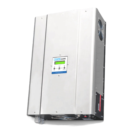
- Page 1 Pure Sine Wave Inverter 5 kW 48V 8 kW 48V User Manual Manual Version: INV-5-8kW-LION- 2021-1-V21R1...
-
Page 2: Table Of Contents
Table of Contents Unpacking and Inspection ......................1 Glossary of Terms.......................... 3 IMPORTANT INFORMATION AND SAFETY INSTRUCTIONS ..........4 INTRODUCTION ........................5 General Description ......................5 Key Features ........................5 OPERATION MODES ......................6 UPS System ........................6 Off-Grid System (No Grid Supply ) ................... 6 Grid Assisted Solar Power System ................... - Page 3 V2 Lithium Ion Interface – Solar MD Logger Wiring Diagram ........19 7.11 7.11.1 100A MPPT and Inverter ..................19 7.11.2 60A MPPT and Inverter ..................19 7.12 V1 Lithium Ion Interface With No BMS ................ 20 7.13 V2 Lithium-Ion Interface With No BMS ................ 21 7.14 Maintenance and service .....................
- Page 4 10.4 Battery Charging Rate ....................30 10.5 AC Input Power From Generator ................. 31 10.6 Battery Boost Voltage ....................31 10.6.1 Battery Boost Voltage Settings ................31 10.7 Battery Float Voltage ....................32 10.7.1 Battery Float Voltage Settings................32 10.8 Battery Boost Time ......................
- Page 5 5kW48 V Inverter Specifications .................. 43 14.2 8kW48 V Inverter Specifications .................. 44 LIMITED CARRY- IN WARRANTY ..................45 REGISTRATION OF MY MICROCARE PRODUCT ............47 This manual applies to the Microcare 5kW & 8kW Inverter with Software Version: V21R1...
-
Page 6: Unpacking And Inspection
1 x V2 Lithium Interface Cable 1 x V2 Lithium Interface Termination Socket 1 x User Manual (Warrantee registration information) The identification labl is position on the top of the inverter. This manual applies to the Microcare 5kW & 8kW Inverter with Software Version: V21R1... - Page 7 Please note that if the LITHIUM-ION Interface is not connected to a BMS, terminate the Inverter and MPPTS as below with the supplied termination sockets. If the termination socket is not fitted to the Inverter • The Inverter will not charge the batteries. •...
-
Page 8: Glossary Of Terms
Glossary of Terms Glossary of Terms Alternating Current Rated battery capacity specified in Ampere-Hour. AC Run To The level the solar regulator will charge the battery to before the inverter switches back to battery power AC Source The primary AC input that is connected to the inverter, e.g., Mains Grid or Generator. -
Page 9: Important Information And Safety Instructions
IMPORTANT INFORMATION AND SAFETY INSTRUCTIONS • Installers should be qualified electricians or technicians. • The installation information in the manual is for information purposes only. • The monitoring and operation information in this manual is intended for anyone who needs to operate the inverter. -
Page 10: Introduction
4 times faster. The Microcare Inverter can run at 200% the capacity continuously when the grid is present and should the grid fail, the Inverter will return to its rated power. Microcare Inverters use galvanic isolation which makes them highly robust and reliable with low standby current and high efficiency. -
Page 11: Operation Modes
OPERATION MODES OPERATION MODES UPS System The inverter is used as an UPS. This operation mode is used for systems that have the grid available as the main AC supply. The grid will supply the load. When the grid supply is interrupted or lost, then the inverter switches to inverter mode. -
Page 12: Inverter Overview
INVERTER OVERVIEW INVERTER OVERVIEW Inverter Front & Side View Figure 4-1 AC Wiring Connectors Remove the AC terminal Cover Plate to access the AC wiring terminals. -
Page 13: Inverter Overview
INVERTER OVERVIEW INVERTER OVERVIEW Inverter Layout Figure 5-1 Top View 1. Inverter Front View 2. LCD display & Keypad 3. Side View 4. Ventilation Grid 5. AC wiring terminal cover 6. Comms Card 7. Top View 8. Identification label 9. Inverter Bottom View 10. -
Page 14: Inverter Installation
INVERTER INSTALLATION INVERTER INSTALLATION Consider the following when installing the inverter. Planning the Installation Location • Install the Inverter indoor in a dry protected location away from any sources of moisture. • Find a suitable temperature resistant surface to mount the inverter. •... -
Page 15: Installing The Inverter Mounting Bracket
INVERTER INSTALLATION Installing the Inverter Mounting Bracket • Find a suitable temperature resistant surface to mount the inverter. • Provide enough space for the routing of external wiring, Sub DB board and additional accessories. • The mounting surface must support the weight of the inverter. •... -
Page 16: General Wiring Information
GENERAL WIRING INFORMATION GENERAL WIRING INFORMATION • Wiring must be performed by qualified personnel / certified electrician. • Familiarize yourself with the content of the manual following before commencing with the wiring. • The line voltage “AC” applied must comply with the inverter’s specified input voltage •... -
Page 17: Earthing Of The Equipment
GENERAL WIRING INFORMATION Earthing Of the Equipment Equipment surge protection products are an effective way of controlling dangerous surges that can enter a facility. When strategically placed and correctly installed, the Surge Protectors will effectively reduce harmful over voltage conditions that can damage electrical and electronic equipment. It is important that the protection system includes both structural and surge protection equipment. -
Page 18: Inverter Neutral Connection
GENERAL WIRING INFORMATION Inverter Neutral Connection 7.2.1 Inverter Connected to the Grid When connecting the inverter to AC from the grid, the inverter input must not be connected via an earth leakage. The earth leakage must be connected directly after the inverter. Keep the inverter neutral input connected to the GRID neutral at all times. -
Page 19: Ac Wiring
GENERAL WIRING INFORMATION AC Wiring The inverter AC input and AC load output wiring must be sized correctly and fitted with appropriate circuit breakers. Refer to Error! Reference source not found. for the correct wiring and circuit b reaker sizes. Pre-Wiring Procedure Make sure that the wiring to and from the inverter is not connected to any AC sources. - Page 20 GENERAL WIRING INFORMATION Figure 7-4: Sample Wiring Diagram...
-
Page 21: Dc Wiring
GENERAL WIRING INFORMATION DC Wiring Warning! The Inverter battery input is not reverse polarity protected. Reverse polarity will damage the unit!! The battery connection leads between the inverter and batteries should be kept to a minimum length. The inverter comes supplied with pre-fitted battery cables and must not be shortened. Shortening the battery leads will void the warranty of the inverter. -
Page 22: V1 Lithium Ion Interface - Freedom Won Bms Wiring Diagram
GENERAL WIRING INFORMATION V1 Lithium Ion Interface – Freedom Won BMS Wiring Diagram 7.9.1 Wiring Designation WIRE COLOUR MPPT WIRE FUNCTION MPPT PIN NUMBER Solar Charge Controller Enable (NO) TURQUIOSE Solar Charge Controller Enable (COM) WIRE COLOUR INVERTER WIRE FUNCTION INVERTER PIN NUMBER YELLOW... -
Page 23: V2 Lithium Ion Interface - Freedom Won Bms Wiring Diagram
GENERAL WIRING INFORMATION V2 Lithium Ion Interface – Freedom Won BMS Wiring Diagram 7.10 7.10.1 100A MPPT and Inverter 7.10.2 60A MPPT and Inverter... -
Page 24: V2 Lithium Ion Interface - Solar Md Logger Wiring Diagram
GENERAL WIRING INFORMATION V2 Lithium Ion Interface – Solar MD Logger Wiring Diagram 7.11 7.11.1 100A MPPT and Inverter 7.11.2 60A MPPT and Inverter... -
Page 25: V1 Lithium Ion Interface With No Bms
GENERAL WIRING INFORMATION 7.12 V1 Lithium Ion Interface With No BMS If the Lithium Ion battery has no BMS installed connect: MPPT with Interface • Connect the Purple wire to the Red wire to enable charging. Inverter with Interface • Connect Yellow wire to the Blue wire to enable the load. •... -
Page 26: V2 Lithium-Ion Interface With No Bms
GENERAL WIRING INFORMATION 7.13 V2 Lithium-Ion Interface With No BMS Please note that if the LITHIUM -ION Interface is not connected to a BMS, terminate the Inverter and MPPTS as below with the supplied termination sockets. If the termination socket is not fitted to the Inverter •... -
Page 27: Maintenance And Service
GENERAL WIRING INFORMATION 7.14 Maintenance and service Caution – Risk of Electric Shock. Batteries may cause electric shock and have a high short-circuit current. Please take the precautionary measures specified below and any other measures necessary when working with batteries. Remove wristwatches, rings and other metal objects. -
Page 28: Inverter Operation
INVERTER OPERATION INVERTER OPERATION Front Panel LCD Display/Keypad and Description Figure 8-1: LCD Display & Keypad The front Panel Display/Keypad indicates the Inverter’s operational information, including output voltage, battery voltage, output load, internal temperature and is used for programming. Panel Display/Keypad operation explained. For ease of explanation the following symbols will be used to represent the Enter, Menu Up and Menu Down Buttons. -
Page 29: Inverter On And Grid Supplying The Load
INVERTER OPERATION 8.2.1 Inverter ON and Grid Supplying the Load INVERTER ERROR Inverter ON and the Battery Supplying the Load “Inverter Mode” 8.2.2 INVERTER ERROR Inverter Displaying WARNING “Battery Low Battery Capacity” 8.2.3 WARNING!!! BATTERY CAPACITY Steady “ON”, Green , Yellow and Red LED INVERTER ERROR Buzzer sounds twice, Press... -
Page 30: Checks Prior To Start-Up
INVERTER OPERATION Checks Prior To Start-Up Ensure that the external AC Grid circuit breaker is turned off. Ensure that the external AC Load circuit breaker is turned off. Ensure that the Inverter Battery Circuit Breaker is turned off. Ensure the INVERTER is mounted vertically. Check if the Input and Output cables are secured. -
Page 31: Start-Up Procedure
INVERTER OPERATION Start-Up Procedure Press and hold the RED PRECHARGE BUTTON for 3 seconds until the display shows writing then turn on the BATTERY CIRCUIT BREAKER while holding the PRECHARGE BUTTON Once the BATTERY CIRCUIT BREAKER has been turned ON, the RED PRECHARGE BUTTON can be released. -
Page 32: Inverter Menu
INVERTER MENU INVERTER MENU In either the inverter ON or OFF mode, use the buttons to view the menu displays on the LCD screen explained below. Power rating of the UPS UPS MODE The load drawn as a % of the rated power is displayed. OUTPUT By turning on a load, the OUTPUT % will change to indicate the LOAD as a % of the unit being used in KW. -
Page 33: System Setup
System Setup ENTER This menu allows the user TO CHANGE the system settings Setup Menu? 9.10 Battery Setup ENTER This menu allows the user TO CHANGE the battery settings Battery Menu? 9.11 Log Menu ENTER Log Menu? 9.12 Exit & Save SETUP MENU This menu allows the user TO SAVE all the new setting changes Exit And Save... -
Page 34: Battery Setup Settings
BATTERY SETUP SETTINGS BATTERY SETUP SETTINGS 10.1 Battery Setup Settings - Quick Reference Guide Menu Settings ENTER Battery Menu ? Sets the battery type: LAY-UPS BATTERY TYPE Lead Acid 100% Lithium Slow Charge CHARGE RATE LAY-UPS 100% AC INPUT POWER Level 1 (Default) Level X Level 2,3,4,5,6... -
Page 35: Battery Setup Procedure
75% of charge rate as per the list supplied below 100% of charge rate as per the list supplied below. Below is the list of available charge amps for the inverters. Table 10-1: Battery Setup – 5kW48V Inverter Battery Charging rates INVERTER Charging Rate (A) -
Page 36: Ac Input Power From Generator
BATTERY SETUP SETTINGS 10.5 AC Input Power From Generator AC INPUT POWER Level X To change the AC INPUT POWER settings, Press This allows the inverter to extract the maximum amount of power from a generator. SELECT The inverter constantly monitors the Voltage from the generator and then applies maximum charge. LEVEL 1 is the highest load to the generator while. -
Page 37: Battery Float Voltage
BATTERY SETUP SETTINGS 10.7 Battery Float Voltage FLOAT XX.XV To change the BATTERY FLOAT VOLTAGE settings, Press This allows the user to adjust the BATTERY FLOAT voltage. The float settings can be changed as follows: 10.7.1 Battery Float Voltage Settings Table 10-3a: Battery Setup - Battery Float Voltage Firmware V21R1 48V System Default –... -
Page 38: Battery Low Voltage Shut Down
BATTERY SETUP SETTINGS 10.9 Battery Low Voltage Shut Down CUT-OFF To change the BATTERY LOW OFF AT settings, Press XX.XV This selects at what BATTERY LOW VOLTAGE the inverter will shut down “Also known as: low battery voltage cut-out” This function prevents the inverter from draining the batteries completely. When the DC voltage drops below a specified level, the inverter will stop functioning. -
Page 39: Setup Menu Settings
SETUP MENU SETTINGS SETUP MENU SETTINGS 11.1 Setup Menu - Quick Reference Guide Menu Sub-Menu Settings ENTER Setup Menu ? SELECT MODE From the Battery Setup menu select the battery type first Lead Acid Battery Run to DC RUN TO Voltage XX.XV Lithium Battery Run To... -
Page 40: Setup Menu Settings
SETUP MENU SETTINGS 11.2 Setup Menu Settings ENTER Press until the ENTER SETUP MENU appears Setup Menu ? Press to enter the SETUP menu. The menu changes to UPS mode By Pressing you can select whether the inverter runs in UPS, Solar Control or Load Shedding mode 11.3 UPS Mode... -
Page 41: Load Shedding Mode
SETUP MENU SETTINGS 11.5 Load Shedding Mode When to select the “Load Shedding Mode” When load shedding is anticipated. SELECT MODE Load Shedding Explanation: Selecting this mode ensures that the load is supplied from the Grid and that Battery Power is reserved for load shedding. -
Page 42: Ac Run To Voltage
SETUP MENU SETTINGS 11.7 AC Run To Voltage AC RUN TO “This setting only applies for Solar Control Mode” XX.XV This allows the user to set the level the solar regulator will charge the battery to before the inverter switches back to battery power. Press to change the AC Run To Voltage, The AC Run To settings can be changed as follows:... -
Page 43: Load Monitoring
SETUP MENU SETTINGS 11.9 Load Monitoring LOAD MONITOR To change the Load Monitoring settings press The sensitivity of the SHORT CIRCUIT TRIP may be changed by 5 different settings. The settings in Table 4 below will determine how the inverter reacts to a short circuit or overload. •... -
Page 44: Load Transfer Time
SETUP MENU SETTINGS • If the grid fails and the load is exceeding 200% of the rated inverter power, the inverter will shut down due to overload. Selecting AC output = 200% for Grid Assisted operation When the Grid supply is available in “Solar Control Mode”, the inverter allows the Grid to supply a load up to 200% for a short period of the rated inverter power. -
Page 45: Logs
LOGS LOGS ENTER Press until the ENTER LOG MENU appears Log Menu? Press to enter the LOG menu. 12.1 Battery Voltages Battery Voltages Displays the max (Vm) and min (Vn) DC battery voltage. Vm: 39.6 Vn: 37.6 Press to view the next log. 12.2 Battery Currents Battery... -
Page 46: No Of Short Circuits
12.12 No of Short Circuits No of Short Circ Displays the Short Circuit counts. 0 counts Press to view the next log. 12.13 Forced Shutdown Counts Forced Shutdown Displays the Forced Shutdown counts due to 0 counts 12.14 Power Failure Counts Power Failure ( R ) To change the Inverter Output Power settings press. -
Page 47: Troubleshooting
TROUBLESHOOTING TROUBLESHOOTING Symptom Possible Cause Remedy Connect inverter input to AC The unit is inverting or not Inverter not charging connected to the grid Source The unit is connected to the grid but is in a mode or stage Inverter not charging that does not use the charger such as Solar Control mode The unit is connected to the... -
Page 48: Specifications Of Inverters
SPECIFICATIONS OF INVERTERS SPECIFICATIONS OF INVERTERS The Specifications apply when the Inverter Setting is set for AC Output = Normal Section10:7 14.1 5kW48 V Inverter Specifications Model 5kW48V Capacity Watt 5000 Nominal Voltage 48 VDC Acceptable Voltage Range 40-60 VDC... -
Page 49: 8Kw48 V Inverter Specifications
SPECIFICATIONS OF INVERTERS 14.2 8kW48 V Inverter Specifications Model 8kW48V Capacity Watt 8000 Nominal Voltage 48 VDC Acceptable Voltage Range 40-60 VDC DC Input Maxi Input Amps 200 A Standby Power 100 W Voltage 230 VAC Amps 35 A < 3 % RMS for entire battery voltage Voltage Regulation range Frequency... -
Page 50: Limited Carry- In Warranty
Removal of serial numbers may void the warranty. All remedies and the measure for damages are limited to the above. Microcare shall in no event be liable for consequential, incidental, contingent or special damages, even if having been advised of the probability of such damages. - Page 51 3. The reason for the return. 4. Microcare must be notified within 7 days of your intention to return the goods which were purchased. 5. All items returned will be inspected prior to refund. If our technicians are not immediately available, the goods will have to be left with us until such time as a technician is available to check the items.
-
Page 52: Registration Of My Microcare Product
REGISTRATION OF MY MICROCARE PRODUCT Product Serial Number: Product Description: Date Purchased From Whom was the Inverter Purchased: Company Name Contact Person Contact Number E-mail Address Installation Company Information: Company Name Contact Person Contact Number E-mail Address Details of Product Owner Name &...
Need help?
Do you have a question about the 5kW48V and is the answer not in the manual?
Questions and answers