Table of Contents
Advertisement
Available languages
Available languages
Quick Links
Advertisement
Table of Contents

Subscribe to Our Youtube Channel
Related Manuals for JBL CSA-2120


Summary of Contents for JBL CSA-2120
-
Page 6: Unpacking Your Amplifier
2.0 Setup 2.1 Unpacking Your Amplifier Please unpack and inspect your amplifier for any damage that may have occurred during transit. If damage is found, notify the transportation company immediately. Only you can initiate a claim for shipping damage. We will be happy to help as needed. - Page 7 Figure 2.2.1 Dimensions Unit: mm [inches] Figure 2.2.2 Mounting Kit long angle bracket flat bracket angle bracket Figure 2.2.3 Rack mounting an amplifier and CST-2120 Transformer Module Solution A: Rack Mounting an Amplifier and CST-2120 Transformer Module To install an amplifier and a CST-2120 transformer module in your cabinet system, refer to Figure 2.2.3 and follow the steps below: Align two modules side by side, with the front panel towards the same direction.
- Page 8 Figure 2.2.4 Rack Mounting Single Amplifier Solution B: Rack Mounting Single Amplifier To install single amplifier in your cabinet system, refer to Figure 2.2.4 and follow the steps below: Attach the long angle bracket to one side of the amplifier that you need to reserve as dummy module with screws.
-
Page 9: Ensuring Proper Cooling
Figure 2.4 Input Wiring Note: Do not use both Euroblock and RCA audio input connectors on a single channel at the same time. 2.3 Ensuring Proper Cooling When using an equipment rack, mount units directly on top of each other. DO NOT block side air vents. -
Page 10: Output Wiring
CST-2120 transformer module with the jumper cable that shipped with the CST-2120 transformer module, see Figure 2.5.1. JBL recommends using pre-built or professionally wired, high-quality, two-conductor, heavy gauge speaker wire. Speakers wires should be twisted cable, if possible. To prevent the possibility of short-circuits, the wires should be stripped back no greater than 6 mm (1/4 inch), see Figure 2.5.2. -
Page 11: Wiring Your Audio System
Figure 2.6 Wiring Audio System Professional audio system Personal audio system 2.6 Wiring Your Audio System Typical input and output wirings are shown in Figure 2.6. INPUTS: Connect input wiring for both channels using either the RCA or the Euroblock input for each channel. OUTPUTS: Maintain proper polarity (+/–) on output connectors. -
Page 12: Connecting To Ac Mains
2.7 Connecting to AC Mains Connect your amplifier to the AC mains power source (power outlet) with the supplied AC power cord. First, connect the IEC end of the cord set to the IEC connector on the amplifier; then, plug the other end of the cord set to the AC mains. WARNING: The third prong of this connector (ground) is an important safety feature. -
Page 13: Operation
10. If the line voltage to the amplifier is too low, the low voltage protection function will be activated. The power indicator will be turned off. CAUTION: JBL is not liable for damage that results from overdriving other system components. -
Page 14: Front Panel Controls And Indicators
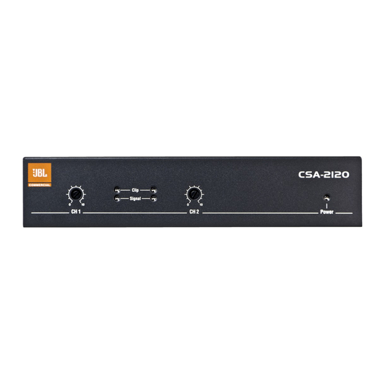
3.2 Front Panel Controls and Indicators Figure 3.2 Front View Level: Rotary level control, one per channel. Meter Group (one per channel): • Clip Indicator: Red LED turns at the threshold of audible distortion. • Signal Indicator: Green LED flashes when a very low-level signal (Threshold -40dB) is present at input. -
Page 15: Appendix A: Optional Item - Transformer Module
The rack-mountable JBL Commercial ® CST-2120 transformer module provides impedance and voltage matching from the CSA-2120 amplifier to drive 70V and 100V distributed speakers systems. This unit allows amplifiers without direct 70V or 100V output capability to drive distributed speaker systems designed to operate at those voltages. -
Page 16: Installation
• Rack mounting single unit • Wall mounting 2. Connect the input of the transformer module to the output of the CSA-2120 amplifier with the shipped 4-pin cable. 3. Determine the proper transformer module tap to use, based on the desired... -
Page 17: Appendix B: Amplifier Specifications
Appendix B: Amplifier Specifications Output Power (two channels at 1 kHz 4 Ohms 120 W power, THD+N<0.5%): 8 Ohms 120 W Frequency Response +1/-1 dB (1 watt into 4 or 8 Ohms): Load Impedance: Rated for 4 or 8 Ohms Sensitivity (8 Ohms load): 1.4 Vrms Signal to Noise Ratio (below rated... -
Page 18: Appendix D: Contact Information
For additional information, please consult JBL Professional Customer Service, your system installer or retailer. On The World Wide Web: www.jblcommercialproducts.com Professional Contacts, Outside the USA: Contact the JBL Professional Distributor in your area. A complete list of JBL Professional international distributors is provided at our U.S.A. Website: www.jblpro.com... -
Page 20: Cómo Usar Este Manual
1.0 Bienvenido El amplificador CSA-2120 de JBL es una herramienta profesional diseñada y ® construida para aplicaciones de sonido instaladas. El amplificador es un modelo de dos canales que ofrece una amplificación analógica simple, con una alimentación universal de modo de interruptor. -
Page 21: Desempaque Su Amplificador
2.0 Configuración 2.1 Desempaque su amplificador Rogamos extraiga e inspeccione el amplificador en busca de daños que puedan haberse producido durante su transporte. En caso de encontrar algún daño, notifíquelo de inmediato a la empresa de transportes. Sólo usted puede presentar una reclamación por daños durante el envío. - Page 22 Figura 2.2.1 Dimensiones Unidad: mm [pulgadas] Figura 2.2.2 Kit de montaje escuadra de montaje larga placa de montaje escuadra de montaje Figura 2.2.3 Montaje en bastidor de un amplificador y de un módulo transformador CST-2120 Solución A: Montaje en bastidor de un amplificador y de un módulo transformador CST-2120 Para instalar un amplificador y un módulo transformador CST-2120 en su sistema, consulte la figura 2.2.3 y siga los siguientes pasos:...
- Page 23 Figura 2.2.2 Montaje en bastidor de un único amplificador Solución B: Montaje en bastidor de un único amplificador Para instalar un amplificador en su mueble, consulte la figura 2.2.4 y siga los siguientes pasos: Atornille la escuadra de montaje larga a un lado del amplificador que necesita reservar como módulo ficticio.
-
Page 24: Seleccione El Cableado Y Conectores De Entrada
Figura 2.4 Cableado de entrada CONECTORES EUROBLOCK RCA-VERBINDUNGEN SUMA MONO LÍNEAS BALANCEADAS CANAL 1 FUENTE ENTRADA CANAL 2 FUENTE ESTÉREO LÍNEAS NO BALANCEADAS CANAL 1 FUENTE ENTRADA CANAL 2 FUENTE Nota: No use conectores de entrada de sonido RCA y Euroblock en un único canal al mismo tiempo. -
Page 25: Cableado De Salida
100V, conecte el amplificador a un módulo transformador CST-2120 con el cable de puente que se envió con el módulo transformador CST-2120, vea la figura 2.5.1. JBL recomienda el uso de cables para altavoces de alta calidad, de dos conductores y de calibre grueso prefabricados o cableados profesionalmente. - Page 26 Figura 2.6 Cablee el sistema de sonido Sistema de sonido profesional Sistema de sonido personal 2.6 Cablee su sistema de sonido El cableado típico de entrada y salida se muestra en la figura 2.6. ENTRADAS: Conecte los cables de entrada para ambos canales usando la entrada de Euroblock o RCA para cada canal.
-
Page 27: Conecte Al Suministro Eléctrico
2.7 Conecte al suministro eléctrico Conecte su amplificador a la fuente de suministro eléctrico (toma de corriente) con el cable de CA provisto. Primero, conecte el extremo IEC del cable al conector IEC del amplificador; luego, conecte el otro extremo del cable a la toma de corriente. ADVERTENCIA: El tercer contacto de este conector (tierra) es una característica de seguridad importante. - Page 28 10. Si la tensión de línea del amplificador es demasiado baja, se activará la función de protección de tensión baja. Se apagará el indicador de encendido. ADVERTENCIA: JBL no es responsable por el daño que resulte de forzar otros componentes del sistema.
- Page 29 3.2 Indicadores y controles del panel frontal Figura 3.2 Vista frontal Nivel: Control de nivel giratorio, uno por canal. Grupo medidor (uno por canal): • Indicador de saturación: El LED rojo se enciende en el umbral de la distorsión audible. •...
-
Page 30: Especificaciones
• Ofrece dos canales de adaptación de impedancia para una operación de "tensión constante" • Ofrece salida de 70V y 100V cuando se usa con amplificadores CSA-2120. Permite integrar con facilidad el CSA-2120 en sistemas distribuidos. Se incluyen conectores de entrada y salida Euroblock extraíbles. -
Page 31: Instalación
1. Si necesita montar el módulo transformador en un bastidor, use un bastidor de equipo estándar de 48,3 cm (19 pulgadas). Puede disponer de las siguientes opciones según su aplicación: • Montaje en bastidor del módulo transformador con un amplificador CSA-2120 • Montaje en bastidor de una única unidad • Montaje en pared 2. - Page 32 Anexo B: Especificaciones del amplificador Potencia de salida(dos canales a una 4 ohmios 120 W 8 ohmios 120 W potencia de 1 kHz, THD+N<0.5%): Respuesta de la frecuencia(1 vatio en 4 +1/-1 dB o 8 ohmios): Impedancia de carga: Clasificada para 4 u 8 ohmios Sensibilidad (carga de 8 ohmios): 1,4 Vrms Relación señal/ruido (inferior a la nominal...
- Page 33 Professional, con su distribuidor o con el minorista. Página web: www.jblcommercialproducts.com Contactos profesionales fuera de EEUU: Contacte con el distribuidor JBL Professional de su zona. En nuestra página web de EEUU aparece una lista completa de distribuidores internacionales profesionales de JBL: www.jblpro.com...
Need help?
Do you have a question about the CSA-2120 and is the answer not in the manual?
Questions and answers