Table of Contents
Advertisement
INSTALLATION AND
USER'S MANUAL
External and internal
temperature recorders
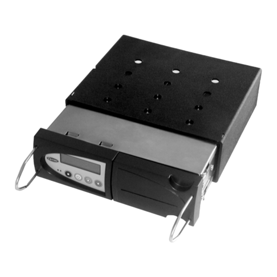
DataCOLD 500 T/R
Carrier Transicold Europe – 10, Bd de l'Oise – 95031 Cergy Pontoise Cédex – France
Carrier Transicold North America, 700 Olympic Drive, Athens, Ga. 30601 - U.S.A.
Carrier Refrigeration Operation 2003 Printed in France 02-03 / 62-61138-20
Advertisement
Table of Contents

Related Manuals for Carrier DATACOLD 500 T/R

Summary of Contents for Carrier DATACOLD 500 T/R
- Page 1 DataCOLD 500 T/R Carrier Transicold Europe – 10, Bd de l’Oise – 95031 Cergy Pontoise Cédex – France Carrier Transicold North America, 700 Olympic Drive, Athens, Ga. 30601 - U.S.A. Carrier Refrigeration Operation 2003 Printed in France 02-03 / 62-61138-20...
- Page 2 INTRODUCTION This manual is a guideline for the installation and use of the DataCOLD 500 T/R temperature recorders. To avoid loss of warranty coverage due to incompetent installation it is most essential to follow the instructions and recommendations of this manual.
-
Page 3: Table Of Contents
TABLE OF CONTENTS GENERAL DESCRIPTION... 4 LCD Display... 4 Keyboard ... 4 Printer ... 5 INSTALLATION... 5 Positioning Connections ... 5 Mounting... 6 Connectors... 8 Wiring...10 Configuration ...10 Final testing Standard Installation...11 Supplementary installation...11 USER MENU'S ...12 Print menu ...12 Alarm menu ...14 User settings ...15 Status menu ...16... -
Page 4: General Description
Keyboard DataCOLD 500 T/R are completely menu controlled. All functions can be carried out via the four colored buttons (like printing, activate alarms or change parameters). The actual function of the buttons are always displayed on the bottom line. -
Page 5: Printer
(meter) of a roll indicates that the paper roll needs to be replaced. (Enclosure B ) Installation In general DataCOLD 500 T/R Temperature recorders are supplied with all required components for a standard installation. A standard installation includes the mounting of the unit itself and mounting and connecting two Temperature sensors. -
Page 6: Mounting
The power supply can be connected directly to the vehicle or Carrier Unit battery. The included 3A (T) floating fuse must be fitted in the +power line direct as close as possible to the power connection. The DataCOLD 500 T/R recorders are suitable for a voltage between 10 - 36 Volt DC. -
Page 7: Optional Mounting Kit
Temperature inputs Digital inputs Optional Mounting kit If no radio slot is available, the recorder should be mounted with the optional mounting kit. This will replace a radio slot and can be fixed either on or under the dashboard as well as on the back wall. Ensure that the position chosen allows the driver to see the display and operate the operator keyboard. -
Page 8: Connectors
DataCOLD T-Version The T-Version has been designed for outside mounting directly on the body. Usually it is fixed under the refrigeration unit on the front side of the body, where it is easily accessible. For fixing proceed as follows: First hold the box in the desired position and mark the mounting holes. - Page 9 WARNING : DISCONNECT THE RECORDER FROM THE BATTERY IF THE REFRIGERATION UNIT IS NOT USED FOR MORE THAN TEN (10) DAYS. Page 9 62-61138-20 (02/03)
-
Page 10: Wiring
Connector CON 3 (digital inputs) DataCold 500 T/R recorders offer the possibility to connect up to 4 digital inputs. Pin 1-8 are accordingly marked with D1–D4 (D1 = Pin 1+2, …). At every opening or closing of the input circuit a status change will be recorded into memory, but only if the input has been activated and configured correctly in the parameter settings. -
Page 11: Final Testing Standard Installation
Changing the language 1. Press the green key and select menu 3.4 with ↑ ,↓ . 2. Press again the green key to edit (enter) the menu 3.4. 3. Select the desired language with < …> and validate with the green key. 4. -
Page 12: User Menu's
User menu's DataCold 500 T/R have four different user menu’s, which are directly accessible via the keyboard: 1. Print menu 2. Alarm menu 3. User settings menu 4. Status menu Print menu Press Blue button. The last selected print choice will be displayed. Printing starts after 2 seconds. - Page 13 ‘Print time period’ is set to “0 hour“ only the ‘Day start time’ is applicable. Page 13 62-61138-20 (02/03)
-
Page 14: Alarm Menu
3.1.7 Day start time A print out starts from the actual time and goes backwards until the time set in this parameter, unless the ‘Print time period’ is shorter. If the ‘Day start time’ is set to “00:00” only the ‘Print period time’ is applicable. This allows you to print back to a maximum of 24 hours. -
Page 15: User Settings
User settings With the user settings several adjustments can be done to offer the user a maximum of user convenience. By pressing the green button the user setting menu will be activated. Toggle with [ ↑ ], [ ↓ ] between the available menu’s (3.1; 3.2; 3.3; …). Between ‘(..)’... -
Page 16: Display Back Light Setting
3.3.6 Display back light setting Set the intensity of the back light to your convenience. The light switches on when you press any button and switches off after 30 seconds. 3.3.7 Keyboard back light setting Set the intensity of the back light to your convenience. The light switches on when you press any button and switches off after 30 seconds. -
Page 17: Parameter Menu
Parameter menu The DataCold 500 T/R recorder has been designed to enable a multiple number of desired applications for individual customers. By using the corresponding parameter settings you can adjust the recorder functionality to the required needs. This chapter gives an overview and structure of the various parameters available. - Page 18 T3 Input T4 Input >on/off. Menu structure as 5.1 >on/off. Menu structure as 5.1 Page 18 62-61138-20 (02/03)
-
Page 19: Menu 6 : Digital Inputs Settings
Menu 6 : Digital inputs settings 4 inputs for status recording, any input can be switched on/off, assigned with a name and a polarity. A number of names are available as a factory setting, to be selected from a list. In the operating mode you can see on the display which inputs are activated. -
Page 20: Menu 8 : Alarm Settings
Menu 8 : Alarm settings 4 Alarm groups– each with a name to assign, upper- and lower temperature limit and a delay time. Each enabled alarm type can be activated by the user for any compartment, although per compartment only one alarm group can be set at the same time. -
Page 21: Menu 10 : General Settings
Menu 10 : General settings General settings for identifying the unit. 10.1 Temperature units >C The units that temperatures will be displayed. Either degrees C, or degrees F. 10.2 Sample rate The interval time in Minutes (1, 2, 3,..,15, 20, 25, 30,.., 60 minutes) for storing a temperature measurement into memory. - Page 22 11.2 COM2 RS-232 port setting Refer to Enclosure E: wiring diagrams to connect the COM2 RS-232 port of the recorder to the micro of the refrigeration unit. • No protocol. • Third party: light protocol to extract part of the data from the recorder. •...
-
Page 23: Accessories And Spare Parts
Accessories and spare parts ITEM PART NUMBER 12-00585-50 12-00585-51 12-00585-52 12-00585-53 12-00585-54 12-00585-56 12-00585-57 12-00585-58 12-00585-59 12-00585-60 12-00585-61 12-00585-62 12-00585-63 12-00585-64 12-00585-65 12-00585-66 12-00585-67 12-00585-68 12-00585-69 12-00585-70 12-00585-71 12-00585-72 12-00585-73 12-00585-74 12-00586-00 12-00587-01 12-00587-02 12-00587-04 62-61146-00 12-60040-00 22-02336-03 22-60296-00 22-60297-00 22-60633-00 22-60731-00 NS →... - Page 24 Page 24 62-61138-20 (02/03)
-
Page 25: Enclosure A Technical Data
• Data ports : b) Ventilation No special requirements. DataCold 500 T/R recorders are designed for use in an automotive environment. c) IP rating DataCOLD T, Trailer version for outside mounting, IP65 DataCOLD R, Cab version for mounting in the cab, IP22 d) Dimensions ( W x H x D) DataCOLD T, 9.65 x 7.95 x 4.3 inches (245 x 202 x 110mm) -
Page 26: Enclosure B Replace Paper Roll
Enclosure B Replace paper roll If a coloured line appears on the last meter of paper, the paper roll needs to be replaced as follow : 1- Push lock lightly upwards and pull the printer module carefully forward. 3- Insert a new paper roll on the spindle. 2- Open the upper part of the front panel. -
Page 27: Enclosure C Factory Settings
Temperature Return Air Temperature Rear Off, Refrigeration Off, Back door Off, Defrost Off, Side door Comp.1 No (Yes with Carrier Unit) Off, Frozen Off, Chilled Off, Dry Off, Free text +59°F (+15°C) -22°F (-30°C) 0.4 inches (10 mm) Actual+average 10 hour... -
Page 28: Enclosure D Failure Codes
Enclosure D Failure codes & Set correction factor procedure If the display shows one of the following values: the input is activated but no sensor is connected. (ii) the sensor has an open circuit (sensor or wire failure.) the sensor has a short (sensor or cable failure.) Procedure to set a Correction factor The DataCOLD 500 R/T recorders have an option to adjust the offset of the A/D converter with a correction factor. -
Page 29: Enclosure E Wiring Diagrams
Enclosure E Wiring diagrams CONNECTOR 1 POWER SUPPLY & DIGITAL OUTPUTS 1 = POWER SUPPLY (+) 2 = POWER NEGATIVE (-) 3 = DISPLAY BACKLIGHT (+) 4 = ALARM O/P TEMP 5 = ALARM O/P DIGIT CONNECTOR 3 DIGITAL INPUTS (configuration example) 1 = SUPPLY POSITIVE (+) 2 = REFRIGERATION (-) 3 = SUPPLY POSITIVE (+) - Page 30 CONNECTOR 2 RS232 a) Serial communication with micro of the refrigeration unit without control panel 1 = GND 2 = RXD 3 = TXD 4 = CTS 5 = RTS DataCOLD 500 b) Serial communication with micro of the refrigeration unit with one control panel and “Y” communication cable Communication cable 2 way P/N : 22-60297-00...
Need help?
Do you have a question about the DATACOLD 500 T/R and is the answer not in the manual?
Questions and answers