Table of Contents
Advertisement
Advertisement
Table of Contents

Related Manuals for Solcon MPS 3000


Summary of Contents for Solcon MPS 3000
- Page 1 MPS 3000 MOTOR PROTECTION SYSTEM Version: 18.7.2006...
-
Page 2: Changes From Mpc2000 To Mps3000
CHANGES FROM MPC2000 TO MPS3000 CHANGES FROM MPC2000 TO MPS3000 Four programmable discrete (digital) inputs to the MPS3000 (one, before – for Key only). Four programmable Analog outputs Four Programmable Analog Inputs with four new trips (protections) Real time clock. Statistical Data of last 10 trips with time &... -
Page 3: Table Of Contents
TABLE OF CONTENTS TABLE OF CONTENTS CHANGES FROM MPC2000 TO MPS3000......................2 TABLE OF CONTENTS............................3 INTRODUCTION ..............................5 Protection Features .............................5 Control Features..............................6 Supervision and Communication Features ......................6 WIRING DIAGRAM - MPS3000..........................7 WIRING DIAGRAM - MPS3000-C ..........................8 REAR PANEL - MPS3000 and MPS3000-C ......................9 MPS3000 TERMINALS............................10 Auxiliary Power Supply............................10 Current &... - Page 4 TABLE OF CONTENTS Statistical Data ..............................59 Fault Data ................................60 TEST / MAINTENANCE OPTIONS ........................61 COMMUNICATIONS – SERIAL LINK ........................63 TECHNICAL SPECIFICATIONS...........................64 Note Installation, operation and maintenance should be in strict accordance with the instructions in this manual, national codes and good practice. Installation or operation not performed in strict accordance with these instructions shall void the manufacturer's warranty.
-
Page 5: Introduction
INTRODUCTION INTRODUCTION The MPS 3000 Motor Protection System is a new generation of micro processor based relay / controller designed to operate with a three (3) phase induction motors. True RMS voltages and currents are measured at a sampling rate of 0.5 ms, enables the MPS3000 to be used with electronic motor drives like soft starters. -
Page 6: Control Features
INTRODUCTION Two levels for most faults Usually used for Alarm and Trip. Protection levels and time delay settings are individually configured using the key pad on the front panel or through communication. Unique Tripping / Alarm options make it possible to program any fault as an Alarm, Trip, both or none. This unique facility also enables controlled fault Reset possibilities. -
Page 7: Wiring Diagram - Mps3000
WIRING DIAGRAM - MPS3000 WIRING DIAGRAM - MPS3000 Page 7 of 67... -
Page 8: Wiring Diagram - Mps3000-C
WIRING DIAGRAM - MPS3000-C WIRING DIAGRAM - MPS3000-C Page 8 of 67... -
Page 9: Rear Panel - Mps3000 And Mps3000-C
REAR PANEL - MPS3000 and MPS3000-C REAR PANEL - MPS3000 and MPS3000-C Page 9 of 67... -
Page 10: Mps3000 Terminals
MPS3000 TERMINALS MPS3000 TERMINALS Auxiliary Power Supply 85…230VDC or AC (50/60) Hz With option (-S) for separate Aux. Power Supply and Control Phase or DC (+) ........61 Voltage: Neutral or DC (-) ........62 Phase or DC (+) ........64 Ground ............ -
Page 11: Analog Outputs
MPS3000 TERMINALS T1 ........... 66+67, 68 T2 ........... 69+70, 71 T3 ........... 72+73, 74 T4 ........... 75+76, 77 T5 ........... 100+101, 102 T6 ........... 103+104, 105 T7 ........... 106+107, 108 (Leave 106 open for thermistor, see note 2 above) T8 ........... 109+110, 111 (Leave 109 open for thermistor, see note 2 above) T9 ........... -
Page 12: Mps3000-C Discrete Inputs
MPS3000 TERMINALS MPS3000-C Discrete Inputs: Local Start-A ........1&24 Close the contact to operate contactor A. Maintained or Momentary contacts can be used. Local Start-B ........2&25 Close the contact to operate contactor B. Maintained or Momentary contacts can be used. Used for low speed of two speed motor and for reversing applications. - Page 13 MPS3000 TERMINALS Closed - To enable the following: Note: For MPS3000, any one of the four discrete inputs (terminals 13.. 16) can be configured as Authorized key. * Change of parameters (through keyboard). * Reset of any alarm/trip, regardless setting. * Reset of the thermal capacity.
-
Page 14: Output Relays
MPS3000 TERMINALS Output Relays The MPS3000 incorporates four output relays. Each has a C/O contact, rated 8 A / 250 VAC resistive, 2000 VA inductive. The four relays can be configured for alarm, alarm fail-safe, trip, trip fail-safe, overload, earth (Ground) Fault, KWH pulses and also for external contactors control required for the MPS3000-C. -
Page 15: Serial Link
MPS3000 TERMINALS MPS3000-C special use: The relays can be configured with contactors control functions which may be required, according to the control application. Output A Relay: Can be configured as one of: * DOL starting * Star period of Star-Delta starting * Forward of a forward-reverse motor * High speed of two-speed motor Output B Relay:... -
Page 16: C/T" Wiring Diagrams
"C/T" WIRING DIAGRAMS "C/T" WIRING DIAGRAMS Three "C/T"s + Ground Fault Core Balance "C/T" It is the preferred connection. It drawback is that a relatively large Core Balance transformer is required. In the following drawings, the 5A inputs are used and the 1A are left open. In this diagram terminal 92 which is the Ground Fault input current gets the sum of the three phase currents. -
Page 17: Front Panel Overview
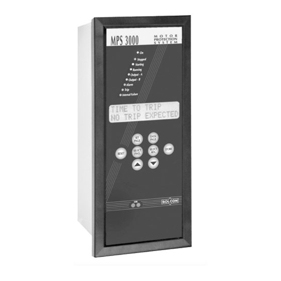
FRONT PANEL OVERVIEW FRONT PANEL OVERVIEW LEDS: ON when auxiliary power supply voltage is connected. Stopped ON in stop condition. Starting ON as a response to start command. Indicates that command is still "ON" and motor's average current is above 115% of rated current. Running ON after completion of starting process. -
Page 18: Keys Overview
FRONT PANEL OVERVIEW Keys Overview Set Page Press to change set parameter pages in positive cyclical order. Data Page Press to change the data page in positive cyclic order. Select FWD Press to forward parameters listed in this page. If key is pressed for more than 0.5 sec, parameters will be displayed at a fast rate. -
Page 19: Front Panel Settings
FRONT PANEL OVERVIEW FRONT PANEL SETTINGS Startup On startup the following occurs: ON and Stopped LED's are turned on The LCD will display: System Parameter *** Settings *** In order to review above page settings, press Select FWD. key. Messages are displayed on the LCD in two lines. * Upper line describes the parameter's name. -
Page 20: Messages
MESSAGES MESSAGES Blinking Messages Blinking messages are displayed as a response to an event. For example: Data Saved OK The message is displayed for a short while (2 seconds) only. Display then returns to the previous message. Blinking messages are usually displayed as a response to an operator action. It is used either to confirm activation of the requested operation, or to indicate reason for not doing so. -
Page 21: Constant Messages
MESSAGES "O.K.". Self Test Failed Displayed as a response to finding an error Error Code = 32 during the operation of Test procedure. In case of test failure, reset and test again. If problem persists then Error Code should be reported to Authorized Factory representative. -
Page 22: Menu Navigation Top
MENU NAVIGATION TOP MENU NAVIGATION TOP Parameter Settings For parameter setting there are five menu options available. By pressing Set Page key the LCD presents the following menus: System Parameter Overload Analog I/O *** Settings *** *** Settings *** *** Settings *** Voltage Tripping / Alarm Power... -
Page 23: Menu
MENU NAVIGATION TOP MENU Below the menu navigation structure and MPS3000 default parameter settings. Navigation Set Page Set Page Set Page Set Page PAGE 0 PAGE 1 PAGE 2 PAGE 3 SYSTEM PARAMETER VOLTAGE CURRENT OVERLOAD *** SETTINGS *** *** SETTINGS *** *** SETTING S*** *** SETTINGS *** SELECT... - Page 24 MENU PARAM. SETTINGS MAX TIME IN STAR UNBALANCE MIN T LOCKED OUT 5 SEC. TRANSITION TIME U/B LEVEL 2 MAX T 30 SEC. Set Page Set Page Set Page Set Page PAGE 4 PAGE 5 PAGE 6 PAGE 8 PAGE 7 POWER TEMPERATURE ANALOG I/O...
- Page 25 MENU Same settings for Analog in 2,3 & 4 Data Page Data Page Data Page Data Page PAGE 10 PAGE 11 PAGE 12 PAGE 13 PAGE 14 MEASURED DATA CALCULATED DATA LOGICAL INPUTS – STATISTICAL DATA FAULT DATA - **** - - **** - CONTACT STATUS - **** -...
-
Page 26: Set Page - Menus
SET PAGE - MENUS SET PAGE - MENUS These menus are accessed by pushing the SET PAGE button. System Parameters System Parameter *** Settings *** Display Description Line Volts (Vn) Rated Line to Line Mains Voltage. 480 Volt Range: 100V-22KV. Increments of : 1V Line Frequency Rated Mains Frequency. - Page 27 SET PAGE - MENUS G/F During Start Ground Fault Level 1 & 2 Alarm / Trip During start period. Intended to be used 100% of FLC with Residual "C/T"s connection, to prevent nuisance tripping with high currents of start process. Range: 1 –...
- Page 28 SET PAGE - MENUS Config. Output B Enables Configuration of Output B relay as: Gnd Fault Trip • Contactor B (the relay is used for controlling the contactor) • Trip • Trip - Fail Safe • Tripping / Alarm (Relay operates by group of faults as set in Tripping/Alarm page).
-
Page 29: Voltage Settings
SET PAGE - MENUS Overload Stall Time Factor). Config. Input B Enables Configuration of Discrete Input B as: External Fault 1 • Contactor A N.O. (for MPS3000-C, for sensing contactor A status). • All Other settings as in Config. Input A Config. - Page 30 SET PAGE - MENUS U/V Auto Restart Enables / Disables the auto Restart features. Disable • Set to “Disable”, if Restart is not required. • Set to “Measured Voltage”, if control power supply (19-20) is stable during mains failure (powered from UPS or DC). Mains Failure is detected and causes motor stop, when voltage decreases below 65% of rated voltage.
-
Page 31: Current Settings
SET PAGE - MENUS Current Settings Current *** Settings *** Display Description Max Start Time Maximum Permitted starting time until current is reduced to 110% of Overload Pickup setting parameter. Protects the motor against too long starting. 10 Sec. Range: 1 – 250 Sec. Increments of : 1 Sec. Number of Starts Maximum Permitted number of starts during "Starts Period". - Page 32 SET PAGE - MENUS O/C Level 2 Delay Time delay for Over Current Level 2 0.5 Sec. Note: When set to 0, actual delay is less than 70mSec. Range: 0 - 4 Sec. Increments of : 0.1 Sec. Unbalance Level 2 Unbalance Current.
-
Page 33: Overload Settings
SET PAGE - MENUS Overload Settings OVERLOAD *** SETTINGS *** Display Description Curve Multiplier Overload Curve Multiplier. Shifts the entire Overload Curve. Range: 1 - 15. Increments of : 1. Overload Pickup Lower threshold for O/L protection. Below this threshold, O/L fault cannot occur. 105% of FLC Range: 60 - 130 % of Motor FLC. - Page 34 SET PAGE - MENUS maximum capacity should be 100%. 155 ° C Range: RTD Middle…250°C. Increment of: 1° C. Thermal Level 1 Thermal Capacity level 1. Normally used for alarm indication. 80% of Capacity Range: 50 - 99 % of maximum thermal capacity. Increments of : 1% Stall Time Fact Stall Time Factor.
-
Page 35: Power Settings
SET PAGE - MENUS Power Settings POWER *** SETTINGS *** Display Description Rated PF at FLC Motor rated (Nameplate) power factor. Required for calculating rated power (based on motor FLC and line volts). 0.88 Lag Range: 0.5 – 0.99. Increment of : 0.01 Under Pwr Level 1 Under power level 1.In percent of rated power, calculated by: √3 * Line Volts * Motor FLC * Rated Power Factor... -
Page 36: Temperature Settings
SET PAGE - MENUS Temperature Settings Temperature *** Settings *** General Note: Level 1 & 2 Fault Fault occurs when temperature is above the set parameter for more than a fixed time period of 2 seconds Display Description RTD Type Resistance Temperature Detector Type. - Page 37 SET PAGE - MENUS T7 Level 1 RTD (or Thermistor) No. 7 level 1 80 EC Range: 0 - 250 EC (or 25.0 K ). Increment: 1 EC (or 1/10 K ) T7 Level 2 RTD (or Thermistor) No. 7 level 2 100 EC Range: 0 - 250 EC (or 25.0 K ).
-
Page 38: Analog I/O Settings
SET PAGE - MENUS Analog I/O Settings Analog I/O *** Settings *** Display Description Analog Out Type Selects between 0..20 mA (or 0..1mA by special order) and 4..20 mA analog outputs (all four). This parameter is common for all four Analog Outputs. 4..20mA Range: 0..20 mA or 4..20mA. - Page 39 SET PAGE - MENUS 0 % of FLC Range: 0..200 (Units change with parameter). Anlog Out 2 Max. Value for maximum (20mA, or 1mA by special order) output. 200 % of FLC Range: 0..250 (Units change with parameter). Anlog Out 3 Par. Analog 3 output parameter.
-
Page 40: Communication Settings
These parameters are numbers of MODBUS actual parameters. By writing to these parameters, user can define a group of up to 20 parameters that can be scanned as one group. See the MPS 3000-10 COMMUNICATION Manual for further reference. Page 40 of 67... -
Page 41: Tripping/Alarm Options
SET PAGE - MENUS Tripping/Alarm Options Tripping / Alarm *** Options *** Tripping Alarm Common Settings All MPS3000 protections share the same settings described below. Accessible via the menu Tripping/Alarm Options. Area Function Setting Observation Mode Trip only Set Trip: Behavior upon Fault ENABLE Trip LED illuminates. - Page 42 SET PAGE - MENUS Area Function Setting Observation DISABLE) "Ground Fault", it is a good practice to prevent Panel Resetting. An authorized person (key holder - few key options are available, according to Discrete input A..D settings)) can always reset any fault. Note: If Authorized Key is locked, front panel Resetting is effective if:...
-
Page 43: Multiple Alarm/Trip Considerations
SET PAGE - MENUS Multiple Alarm/Trip considerations The MPS3000 is designed to accept and store the first alarm it detects. If this alarm has not been reset and an additional alarm occurs, the MPS3000 will not display the second alarm on the LCD nor assign it to the Fault Data page. -
Page 44: Tripping/Alarm Individual Settings
SET PAGE - MENUS Tripping/Alarm Individual Settings Maximum Start Time Fault occurs when starting time is longer then "Maximum Start Time" setting. The MPS3000 assumes end of starting process, when motor current decreases below 110% of the "Overload Pickup" value. For a default value of 105%, end of starting process is detected at 115% of Motor Full Load Current (FLC). - Page 45 SET PAGE - MENUS Over Current Level 1- Jam This identifies a jam condition for a "running" motor. Fault occurs if after start process has ended, motor average current increases above O/C Level 1 setting value for more than O/C LEVEL 1 Delay. Auto reset, when Enabled, occurs when current decreases below O/C Level 1, or when motor stops or trips.
- Page 46 SET PAGE - MENUS Cool T Run This is the Cooling Time Constant for a running motor. When motor current is below the Overload Pickup value, Thermal Capacity is exponentially reduced, simulating motor cooling. Two different cooling time constants must be used.
- Page 47 SET PAGE - MENUS Thermal Level 1 This setting parameter is intended to be used for alarm only. When Thermal Capacity exceeds the set value, and if enabled, the MPS3000 sets an alarm signal. A host computer can use this signal to read "Time to Trip" and determine the time left until the MPS3000 will trip.
- Page 48 SET PAGE - MENUS Thermal Overload Table: I / In TIME I / In TIME I / In TIME I / In TIME I / In TIME I / In 1.01 26122 1.05 5122 1.10 2500 3.60 43.9 6.10 14.5 8.60 11.10 1.20...
- Page 49 SET PAGE - MENUS Thermal Capacity Reset Method It is not possible to reset (to empty) the thermal capacity. Reset, of "Thermal Level 2", is prevented until "Thermal Capacity "cools down" bellow 50%. Therefore, even for a “Key Holder” reset of Thermal Level 2 trip is not possible for a cooling down period of time. Emergency Restart If one of the Discrete inputs A,B,C or D is configured as an Emergency Restart input and if this input (Emergency Restart Switch) is closed, then the Thermal Capacity automatically resets to 0 every time the motor...
- Page 50 SET PAGE - MENUS Unbalance Protection Notes: 1. Select the required trip/alarm time on the vertical axis (at 10% unbalance). 2. Draw an horizontal line at the selected point (for example, 5 Sec.). 3. Select an unbalance point (for example 40%). 4.
- Page 51 SET PAGE - MENUS Ground Fault Level 2 (GND Fault Level 2) Fault occurs when Ground current exceeds "GND Fault Level 2" setting for more than "G/F Level 2 Delay" setting. Minimum setting of "G/F Level 2 Delay" is 0. At 0 setting, the actual time delay is less than 70 ms. Auto reset, when Enabled, occurs when Ground current decreases below "GND Fault Level 2"...
- Page 52 SET PAGE - MENUS In the MPS3000, each one of the Discrete inputs A...D can be configured for an External Fault. The MPS3000-C, has additional three inputs specifically designed for external faults 1...3. Auto reset of External Fault x, when Enabled, occurs when the "External Fault x" input circuit opens. Temperature 1..
-
Page 53: Tripping/Alarm Default Settings
SET PAGE - MENUS Auto reset, when Enabled, occurs when the power increases above "Under Power Level 1" level or when the motor trips. Note: Set Trip and Alarm to DISABLE, if three phase voltage is not connected. Under Power Level 2 For a running motor, fault occurs when motor power decreases below "Under Pwr Level 2"... - Page 54 SET PAGE - MENUS 43. RTD 9 Level 2 ( - ) ( ) ( - ) ( ) ( - ) ( ) ( + ) ( ) ( + ) ( ) ( - ) ( ) ( - ) ( ) Always 44.
-
Page 55: Data Page - Menus
DATA PAGE - MENUS DATA PAGE - MENUS These menus are accessed by pushing the Data Page button. Measured Data Measured *** Data *** Display Description Vp1 Vp2 Vp3 Phase to Neutral voltages. 277 277 277 V Range: 100 V - 12.7 KV. VL12 VL23 VL31 Line to Line Voltages. -
Page 56: Calculated Data
DATA PAGE - MENUS Calculated Data Calculated *** Data *** Display Description Motor Load Curr. Motor current as a percentage of Motor FLC. 90 % of FLC Range: 0 - 1200% of Motor FLC. Equivalent Curr. Equivalent Motor current (increased by unbalance according to Unbalance K 90 % of FLC Factor) as a percentage of Motor FLC. -
Page 57: Logical Inputs Contact Status
DATA PAGE - MENUS Logical Inputs Contact Status Logical Inputs Contact Status It is possible to check the status of any logical input. Used to check the wiring for system maintenance and debugging. Note: If the MPS3000 is in "Protection Only" mode only four of the following parameters are displayed: Discrete Input A, Discrete Input B, Discrete Input C and Discrete Input D. - Page 58 DATA PAGE - MENUS Local / Remote Local / Remote selector switch input contact status. Open = Local Range: Open = Local, Closed = Remote PLC Control PLC / Serial port selector switch input contact status. Open = PLC Range : Open = PLC, Closed = Serial port PLC Control - A PLC contactor - A Open = Stop...
-
Page 59: Statistical Data
DATA PAGE - MENUS Statistical Data Statistical Data - **** - Total Run Time Total run time since commissioning. 10137.5 hours Range: 0-30,000 hours. Total # of Start Total number of starts since commissioning. 1017 Range: 0-65535 Total # of Trips Total number of trips since commissioning. -
Page 60: Fault Data
DATA PAGE - MENUS Fault Data Fault Data - **** - Last Trip Last active fault that was Enabled as a Trip. RTD 3 Level 2 Range: all 52 faults. Last Alarm Last active fault that was Enabled as an Alarm. Load Increased Range: all 52 faults. -
Page 61: Test / Maintenance Options
TEST / MAINTENANCE OPTIONS TEST / MAINTENANCE OPTIONS Push Set Page & ▼simultaneously to enter the test & Test & Service page. Test/Maintenance *** options *** The test page is used for running the self-test, displaying program version, storing factory default parameters into the non volatile memory, resetting and storing statistical data, setting of Real Time Clock and for Fault Simulation. - Page 62 TEST / MAINTENANCE OPTIONS Simul. VL1, 2, 3 For Fault Simulation. Set here the required Line to Line voltages (one 400 VOLT setting for the three line to line voltages). No need to press the Store key. Can be changed before or while simulation is “running”. Default value is automatically set to LINE VOLTS (Vn) setting at system page.
-
Page 63: Communications - Serial Link
COMMUNICATIONS – SERIAL LINK TECHNICAL SPECIFICATIONS COMMUNICATIONS – SERIAL LINK The MPS3000 is equipped with a powerful data communication system, operating beyond a motor protection controller into the realm of a complete motor management system. This communication system is unmatched in its reliability, flexibility and ease of use providing the ideal basis for the design of a modern motor management system. -
Page 64: Technical Specifications
TECHNICAL SPECIFICATIONS TECHNICAL SPECIFICATIONS Auxiliary Power Supply AC /DC Power Supply: Standard voltage version: 85 - 250 V (for 110V or 220V AC or DC) Low voltage version: 19 - 60 V (for 24V or 48V AC or DC) Frequency: DC, 45 to 65 Hz. Power consumption: Less than 20 VA Phase Current Inputs (three current) Method... - Page 65 TECHNICAL SPECIFICATIONS Total Run Time Accuracy: ±2%. Current Unbalance Alarm and Trip Method: Unbalance = 100 * (Negative Sequence Current / Positive Sequence Current) [%] If Motor Load < 100% then multiply by * (Motor Load / 100) This is to prevent nuisance tripping at low current levels. Level 1 Threshold Unbalance Level 1: 50% of Unbal Current setting ±...
- Page 66 TECHNICAL SPECIFICATIONS CASE AND CUTOUT DETAILS Page 66 of 67...
- Page 67 TECHNICAL SPECIFICATIONS Acronyms Description Voltage Transformer Current Transformer Direct online Page 67 of 67...
Need help?
Do you have a question about the MPS 3000 and is the answer not in the manual?
Questions and answers
HOW IS UNDERVOLTAGE CALCULATED, IS IT THE AVERAGE VALUE OF THREE LINE VOLTAGES, PLEASE ADVICE?
The provided context does not explicitly describe how undervoltage is calculated for the Solcon MPS 3000 or whether it is based on the average value of the three line voltages. However, it mentions that faults occur when the average line voltage decreases below a specified threshold. This suggests that undervoltage detection may be based on the average of the three line voltages, but it is not explicitly confirmed.
This answer is automatically generated