Table of Contents
Advertisement
Advertisement
Table of Contents

Related Manuals for Solcon TPS


Summary of Contents for Solcon TPS
- Page 1 Solcon Industries Ltd. www.solcon.com Ver. 22042019...
-
Page 2: Table Of Contents
3.1 Introduction ..........................5 3.2 Rating, Frames sizes and Weights .................... 5 Refer to section 5 page 15 for detailed dimensional drawings ............5 3.3 TPS Selection ..........................5 3.4 Ordering Information ........................6 3.5 Mains and control description ....................7 ... - Page 3 7.7.9 Fault data – page 9 ...................... 38 8. TROUBLE SHOOTING ......................39 8.1 Warranty Claim and Fault Report .................... 41 To be completed By Solcon Service Dept................. 41 Return Material Authorization Number ..................41 TECHNICAL SPECIFICATIONS ..................... 42 9. ...
-
Page 4: Safety & Warnings
Utilization category is AC-51: 1,4 x Ie – 1 s, uninterrupted duty. For further information, see Technical Specification Warnings Internal components and PCBs are at mains potential when the TPS is connected to mains. This voltage is extremely dangerous and will cause death or severe injury if contacted. -
Page 5: Technical Data
TPS Selection Select the TPS according to LOAD RATED CURRENT(FLA) - as indicated on its nameplate. Note: TPS withdrawn current by the load must not exceed TPS RATED CURRENT in each and every phase of the TPS! ________________________________________________________________________________________________... -
Page 6: Ordering Information
Description Standard Example: TPS rated 820A, mains voltage - 230V, control voltage- 230VAC, control inputs- 48VDC Modbus communication card, Harsh environment treatment, Synchronized TPS and standard front panel: TPS 820 - 230 – 230 - 48 - 3M+8+SYNC – S... -
Page 7: Mains And Control Description
400V applies for 230 to 400V. U, V, W Connection to resistive/inductive load. Load connection must be programmed to TPS. Refer to section 3.7 page 9. Connection to Ground. Terminal 1 Control phase (Positive – for DC control) Three control voltages are available:... - Page 8 Sync. signal use Shielded twisted pair, for Terminal 19 Synchronization signal (-) (Optional) daisy chaining. Up to 10 TPS units can be connected for master slave configuration. Master Slave configuration is designed for units located in the vicinity of 20 meter maximum. Refer to section 3.9 page 11.
-
Page 9: Input / Output Indication
Input / Output indication Load Connections The TPS can be connect the load as shown in section 4.1 on page 12. The available configurations are: Wye with Neutral Connected, Wye with Neutral not Connected, Delta or inside Delta. Load connection type must be programmed to TPS. Refer to section 7.7.1 page 28. -
Page 10: Phase Control
Phase control to zero crossing (Soft start) 3.8.3 The user can program a time of which the TPS will function in PHASE CONTROL and then change to ZERO CROSSING mode. This mode of operation allows soft starting of the load. This mode is recommended when load resistance has a temperature dependant characteristic (lower resistance when cold). -
Page 11: Synchronized Mode
This mode of operation is applicable only if mode of operation is set to ZERO CROSSING. In this mode of operation the TPS Sync. Terminals should be wired in “daisy chain” as shown in section 4.4 on page14. This mode is used to time share the ON time (Ton) period between the units. -
Page 12: Recommended Wiring Scheme
Connecting to non symmetrical loads might damage the load! When WYE, NEUTRAL NOT CONNECTED (NC) applies set the UNBALANCE protection to the lowest practical value and trip the TPS upon UNBALANCE or else load will damage. Refer to section 7.7.3 on page 32. -
Page 13: Inside Delta Wiring
(Not shown) (5) – Potentiometer control is only possible if option P (Potentiometer control) is ordered. (6) – Only short current protection is mandatory in models other than 1000V. The TPS has a built-in over current protection. -
Page 14: Communication And Synchronization Wiring
(4) - Synchronized mode cannot be implemented if one current analogue input is connected to several TPS units in series. Wiring Notes When mains voltage is connected to the TPS, even if control voltage is WARNINGS! disconnected, full voltage may appear on the TPS load terminals. -
Page 15: Short Circuit Protection
Transient Protection 4.5.2 Line transient voltages can cause a malfunction of the TPS and damage to the thyristors. All TPS units incorporate Metal Oxide Varistors (MOV) to protect from normal line voltage spikes. When higher transients are expected, additional external protection should be used (consult factory). - Page 16 16 • Dimensions ________________________________________________________________________________________________...
- Page 17 17 • Dimensions ________________________________________________________________________________________________...
- Page 18 18 • Dimensions For other models dimensions – consult factory. ________________________________________________________________________________________________...
-
Page 19: 1000Vac Models
19 • Dimensions 1000VAC Models Note: In 1000V models semiconductor protection fuses for “type 2 coordination" are built –in. ________________________________________________________________________________________________... -
Page 20: Installation
It is recommended to mount the TPS directly on the rear metal plate for better heat dissipation. Note: Do not mount the TPS directly on the rear metal plate in case a ventilation fan or ventilation opening is on the back side of the TPS. -
Page 21: Jumpers Settings For Analogue Input Configuration
Jumpers settings for analogue input configuration See next page for jumpers location. The TPS incorporates 4 jumpers which configure terminals 16 & 17 to work as a voltage reference input, current reference input or voltage free potentiometer input. Jumpers must be set correctly prior to start up. - Page 22 I average, 0-100% OF LOAD RATED CURRENT. I1, 0-100% OF LOAD RATED CURRENT. I2, 0-100% OF LOAD RATED CURRENT. I3, 0-100% OF LOAD RATED CURRENT. ANALOG INPUT (reflection of analogue input to the TPS) Dip No. 4-20 mA 0-20 mA 0-10VDC Dip-Sw.
-
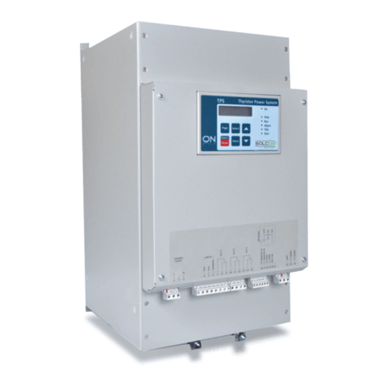
Page 23: Control Keypad
While underline mark does not show – Select key goes “forward” When TPS is in latched trip or in alarm status allows the user to reset the unit. The Reset key has to be pressed for 1 second in order to reset the TPS. -
Page 24: Status Leds
24 • Control Keypad Status LEDs. Green Lights when Control Supply voltage is connected to the TPS Lights when TPS is in stop condition. (Before RUN command is initiated) Stop Green Lights when TPS is feeding the load. Lights during alarm condition. -
Page 25: Mode
25 • Control Keypad DATA SAVED OK At this point (If “default parameters” were obtained) the TPS goes back to the root menu. In order to continue the TEST/MAINTENANCE procedure press Select several times until LCD displays: CLEAR NOW? STATISTICAL DATA To clear “statistical data”... -
Page 26: Mode Pages, Parameters & Default Values
0 % OF FLA LINE FREQUENCY ANALOG IN T. CONST 1.0 U/C DELAY MASTER/SLAVE 50 Hz SEC. 10.0 SEC. TPS RATED CURR. AUX. IN TYPE OVER CURRENT NO. OF SYNC UNITS 100 AMP. REMOTE RESET 120 % OF FLA LOAD RATED CURR. - Page 27 27 • Control Keypad COMM.PARAMETERS ACTUAL DATA STATISTICAL DATA FAULT DATA - **** - - **** - SETTINGS --****-- See page 36 See page 37 See page 38 See page 38 Display and default Display Display Display values COMM. PROTOCOL TOTAL RUN TIME LAST TRIP MODBUS...
-
Page 28: Main Parameters Settings
0.1kW- Sets load rated power. 69.3 KW 3600kW This parameter is set to enable the TPS to close a control loop when in PHASE CONTROL- POWER mode of operation. Refer to section 3.8.4 on page 10. CONNECTION TYPE INSIDE DELTA, Sets connection mode of the TPS. - Page 29 To store selected parameters, press Store key. Note: Storing more than one parameter possible only when the TPS is not running. While TPS is running each parameter can be changed individually by pressing Store key after modifying the parameter. When parameters are correctly stored, the LCD will...
-
Page 30: I/O Parameters
0.0 SEC. – 10.0 SEC. Sets TPS time constant. 1.0 SEC. When starting the TPS, even if analogue input is high, the ANALOG IN T. CONST function will gradually increase the “internal” value of the analogue input while TPS will function in PHASE CONTROL mode. - Page 31 31 • Control Keypad I/O PARAMETERS SETTINGS CONFIG OUT B Same as CONFIG OUT Sets TPS functions of output relay B (Terminals 10, ALARM-FAIL SAFE A – See above. 11, 12) Same as CONFIG OUT A – See above. OUT B RELAY DLY 0.0 SEC.-60.0 SEC.
-
Page 32: Protection Parameters
Sets the value in % of “load rated current” below which the 0 % OF FLA UNDER CURRENT protection is triggered. Note: When TPS is in ZERO CROSSING mode of operation, the measured current used for this function is the ON state current value. U/C DELAY 0.1 SEC.-60.0 SEC. - Page 33 0 % OF Pn which the UNDER POWER protection is triggered. Note: When TPS is in ZERO CROSSING mode of operation, the measured power taken for this function is the ON State power X ON time/ (ON time+ OFF time).
-
Page 34: Load Sheding Parameters Settings
– Load Shedding feature is disabled. – The TPS unit is controlled by another TPS unit SLAVE programmed as MASTER. – The TPS unit controls a number (up to 9) of other MASTER TPS units Note: Synchronized mode cannot be implemented if one current analog input is connected to several TPS units in series. -
Page 35: Tripping/Alarm Prameters
35 • Control Keypad 7.7.5 Tripping/alarm prameters – page 5 For easy viewing, tripping/alarm pages are not listed as in other pages but as a table. Notes: All protections MUST be programmed in this page in order to be operative!! Each of the faults listed below can be programmed as DISABLED (-) or ENABLED (+) The table below shows factory defaults. -
Page 36: Comm.parameters
Note: When FULL option is selected, the wired analog input (Terminals 16, 17 and 20) of the TPS is not active. STORE ENABLE Same as STORE ENABLE MAIN PARAMETERS COMM. -
Page 37: Actual Data
ANALOG INPUT Displays ANALOG INPUT rate. Displays currents of 3 phases. The current shown is when TPS is in “ON” during the “ON-OFF CYCLE T” in “ZERO CROSSING” MODE. This display (with “ON” shown on top left of the display) shown in “ZERO CROSSING”... -
Page 38: Statistical Data
0 HOURS TOTAL # OF TRIPS Displays TOTAL # OF TRIPS since last statistics reset. TOTAL ENERGY Displays TOTAL ENERGY drawn by the TPS in KWH since last statistics reset. 0 KWH 7.7.9 Fault data – page 9 FAULT DATA... -
Page 39: 39 • Trouble Shooting
For more information on adjusting UNDER CURRENT refer to section 7.7.5 on page 32 OVER CURRENT Trips/Alarms if TPS if UNDER CURRENT conditions exist. For more information on adjusting OVER CURRENT refer to section 7.7.5 on page 32 UNBALANCE LVL 1, Trips/Alarms if UNBLANCE LEVELS exist. - Page 40 Trips/Alarms when TPS gets an external input indicating a fault. COMM PORT Trips/Alarms when communication error occurs. FAILED Check wiring, Reset the TPS and try again. If this failure happands again consult factory. INTERNAL Trips/Alarms when an internal failure is detected by the microprocessor.
-
Page 41: Warranty Claim And Fault Report
Remarks By Distributor: We declare that product has been correctly Warranted repair/replacement applied, installed and operated, in accordance with Solcon’s Yes / No written instructions, appropriate codes, regulations and good practice, within the limits of rated capacity and normal usage. -
Page 42: 42 • Technical Specifications
120 or 230VAC, 110VDC+10% -15% (to be specified in order) Frequency 50 / 60 Hz Controlled Phases Three Short-circuit Current 25kA for TPS 1000V models, type 2 coordination when equipped with fuses listed on section 4.5.1 page 15. Form Designation Form 4 1.10 Rated Insulation Voltage...
Need help?
Do you have a question about the TPS and is the answer not in the manual?
Questions and answers