Advertisement
Quick Links
SERVICE MANUAL
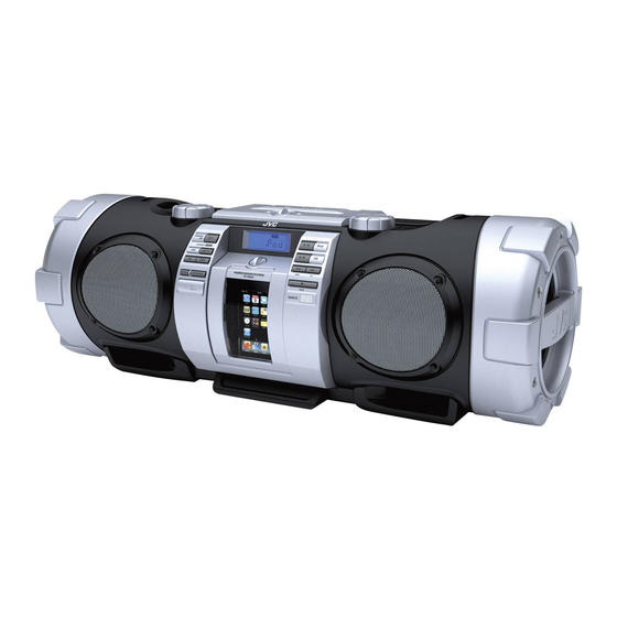
POWERED WOOFER CD SYSTEM
RV-NB50B, RV-NB50E, RV-NB50EN,
4 S ERVICE MANUAL
2010
MB723<Rev.003>
RV-NB50EV, RV-NB51WE, RV-NB51WEN,
RV-NB51WEV, RV-NB52BB, RV-NB52BE,
RV-NB52BEN, RV-NB52BEV, RV-NB50J,
RV-NB50C, RV-NB50US, RV-NB50A,
COPYRIGHT © 2010 Victor Company of Japan, Limited
Lead free solder used in the board (material : Sn-Ag-Cu, melting point : 219 Centigrade)
1
PRECAUTION. . . . . . . . . . . . . . . . . . . . . . . . . . . . . . . . . . . . . . . . . . . . . . . . . . . . . . . . . . . . . . . . . . . . . . . . . 1-3
2
SPECIFIC SERVICE INSTRUCTIONS . . . . . . . . . . . . . . . . . . . . . . . . . . . . . . . . . . . . . . . . . . . . . . . . . . . . . . 1-5
3
DISASSEMBLY . . . . . . . . . . . . . . . . . . . . . . . . . . . . . . . . . . . . . . . . . . . . . . . . . . . . . . . . . . . . . . . . . . . . . . . 1-5
4
ADJUSTMENT . . . . . . . . . . . . . . . . . . . . . . . . . . . . . . . . . . . . . . . . . . . . . . . . . . . . . . . . . . . . . . . . . . . . . . . . 1-9
5
TROUBLESHOOTING . . . . . . . . . . . . . . . . . . . . . . . . . . . . . . . . . . . . . . . . . . . . . . . . . . . . . . . . . . . . . . . . . . 1-9
All manuals and user guides at all-guides.com
RV-NB52BJ
TABLE OF CONTENTS
COPYRIGHT © 2010 Victor Company of Japan, Limited
No.MB723<Rev.003>
2010/4
Advertisement

Related Manuals for JVC RV-NB50B


Summary of Contents for JVC RV-NB50B
-
Page 1: Table Of Contents
All manuals and user guides at all-guides.com SERVICE MANUAL POWERED WOOFER CD SYSTEM RV-NB50B, RV-NB50E, RV-NB50EN, MB723<Rev.003> 2010 4 S ERVICE MANUAL RV-NB50EV, RV-NB51WE, RV-NB51WEN, RV-NB51WEV, RV-NB52BB, RV-NB52BE, RV-NB52BEN, RV-NB52BEV, RV-NB50J, RV-NB50C, RV-NB50US, RV-NB50A, RV-NB52BJ COPYRIGHT © 2010 Victor Company of Japan, Limited... - Page 2 All manuals and user guides at all-guides.com SPECIFICATION Disc player CD capacity Signal-to-noise ratio 85 dB Dynamic range 90 dB Tuner FM tuning range 87.50 MHz - 108.00 MHz Antenna FM telescopic antenna General 8 cm (3 3/16”) cone × 2 Speakers Full range 16 Ω...
-
Page 3: Precaution
All manuals and user guides at all-guides.com SECTION 1 PRECAUTION Safety Precautions (1) This design of this product contains special hardware and voltmeter. many circuits and components specially for safety purpos- Move the resistor connection to each exposed metal es. For continued protection, no changes should be made part, particularly any exposed metal part having a return to the original design unless authorized in writing by the path to the chassis, and measure the AC voltage across... - Page 4 All manuals and user guides at all-guides.com Preventing static electricity Electrostatic discharge (ESD), which occurs when static electricity stored in the body, fabric, etc. is discharged, can destroy the laser diode in the traverse unit (optical pickup). Take care to prevent this when performing repairs. 1.5.1 Grounding to prevent damage by static electricity Static electricity in the work area can destroy the optical pickup (laser diode) in devices such as laser products.
-
Page 5: Specific Service Instructions
All manuals and user guides at all-guides.com SECTION 2 SPECIFIC SERVICE INSTRUCTIONS This service manual does not describe SPECIFIC SERVICE INSTRUCTIONS. SECTION 3 DISASSEMBLY Main body (Used figure were RV-NB50E) (2) Remove the ten screws C attaching the Rear cabinet. (See Fig.3) 3.1.1 Removing the Punching panel (See Fig.1) (3) Remove the two screws D attaching the CD mechanism. - Page 6 All manuals and user guides at all-guides.com (5) Disconnect the connector wire from Power supply board 3.1.4 Removing the Power supply board (See Fig.8) connected to connector CN301 of the Main board. (See (1) Remove the two screws F and two screws G attaching the Fig.5) Power supply board.
- Page 7 All manuals and user guides at all-guides.com (3) Disconnect the card wire from Main board connected to (2) Disconnect the connector wire from Main board connected connector CN450 of the iPod board. (See Fig.11) to connector of the Mechanism board. (See Fig.14) (4) Disconnect the connector wire from Right key board con- nected to connector CN303...
- Page 8 All manuals and user guides at all-guides.com 3.1.7 Removing the iPod board (See Fig.17) 3.1.10 Removing the Key board (See Fig.20) (1) Remove the two screws J attaching the iPod board. (1) Remove the twelve screws M attaching the Key boards. Fig.20 3.1.11 Removing the Right speakers (See Fig.21, 22, 23) (1) Remove the two screws N attaching the Woofer, (See...
-
Page 9: Adjustment
All manuals and user guides at all-guides.com (3) Remove the four screws Q attaching the Main speaker. 3.1.12 Removing the Left speaker (See Fig.23) (1) Left speaker removing method as follow the 3.1.11 Re- moving the Right speakers. Fig.23 SECTION 4 ADJUSTMENT This service manual does not describe ADJUSTMENT. - Page 10 All manuals and user guides at all-guides.com Victor Company of Japan, Limited Home Entertainment Business Division Personal AV Operation 10-1,1chome,Ohwatari-machi,Maebashi-city,371-8543,Japan (No.MB723<Rev.003>) Printed in Japan...
- Page 11 All manuals and user guides at all-guides.com SCHEMATIC DIAGRAMS POWERED WOOFER CD SYSTEM RV-NB50B, RV-NB50E, RV-NB50EN, RV-NB50EV, RV-NB51WE, RV-NB51WEN, RV-NB51WEV, RV-NB52BB, RV-NB52BE, RV-NB52BEN, RV-NB52BEV, RV-NB50J, RV-NB50C, RV-NB50US, RV-NB50A, RV-NB52BJ Lead free solder used in the board (material : Sn-Ag-Cu, melting point : 219 Centigrade)
- Page 12 All manuals and user guides at all-guides.com In regard with component parts appearing on the silk-screen printed side (parts side) of the PWB diagrams, the parts that are printed over with black such as the resistor ( ), diode ( ) and ICP ( ) or identified by the "...
- Page 13 All manuals and user guides at all-guides.com Block Diagram S407 S411 IC401 Operation Remocon Switch VR401 M VOLUME KEY1 IC302 T5CL8 IC304 S401 S406 D401 AT2402 SYSTEM Operation Standby Switch EEPROM IC001 VR402 Q001 3.3V OUT MICON S4702S TO FM ANT W VOLUME KEY2 2SC3052F...
- Page 14 All manuals and user guides at all-guides.com Standard schematic diagrams <Main Section 1> M1.5V C716 D1.5V C717 B16 RESET B[0:30] R719 R705 PICK UP C714 UNIT CN701 A3.3V C715 C701 C702 VREF RESET C704 C706 R704 SVCC R789 VCoi SDCK Pio7 C707 C705 RVDD3...
- Page 15 All manuals and user guides at all-guides.com <Main Section 2> To Key section (LCD PCB) CN403 TURDS TURST TUSCLK TUSDO IPOD_CHG 5VS/W IPOD_RX KEY1 IPOD_TX C323 IPHONE_DET To Key section C324 100P VOL+ IPOD_DET 100P CN402 C325 IPOD_RST VOL- JR301 POWER_ON JR302 SUB_VOL3...
- Page 16 All manuals and user guides at all-guides.com <Main Section 3 and iPod section> iPod connection section IPHONE_DET IPOD_RST IPOD_TX IPOD_RX JK450 IPOD_DET CN450 VOLSDA FUNCTION AMP F/W_GND VOLSCL F/W_GND iPod 3.3V C214 C259 IC203 C277 TPA+ C257 iPod Buffer USB_0+ R218 C261 R240...
- Page 17 All manuals and user guides at all-guides.com <Main Section 4> 15W/7ohm 5.6K R101 R103 C107 R105 CN102 AGND IC101 R102 R104 R106 10 11 C108 5.6K TDA7266SA AMUTE R109 R110 R168 IC102 5W/16ohm 470u/25V Q101 MUTE PVD1 STBY PVD1 15W/7ohm VIN1+ OUT1+ C150...
- Page 18 All manuals and user guides at all-guides.com <Key Section> IC401 GND VCC Power board(1) R402 R401 KEY1 VOL+ To Main section 2 AC IN CN604 CN605 CN606 CN303 VOL- C401 2P/2.0 2P/2.0 iPod S407 CN402 CN601 2.0/4P AC DETJ S408 R601 To Main section 4 SKIP+...
- Page 19 All manuals and user guides at all-guides.com Printed circuit boards <Main board> (Lead free solder used in the board (material : Sn-Ag-Cu, melting point : 219 Centigrade)) (forward side) CN102 C020 R012 R011 R013 L002 JK430 C165 C019 C016 C164 C021 C268 C179...
- Page 20 All manuals and user guides at all-guides.com <Main board> (Lead free solder used in the board (material : Sn-Ag-Cu, melting point : 219 Centigrade)) (reverse side) D434 D433 D431 D432 C431 C434...
- Page 21 All manuals and user guides at all-guides.com <Key board> (Lead free solder used in the board (material : Sn-Ag-Cu, melting point : 219 Centigrade)) SKIP- (forward side) S408 S410 JW11 STOP S407 S411 CN402 1 RMC iPod 270-ST0004-B10X1 2 KEY1 3 VOL+ IC401 4 VOL-...
- Page 22 All manuals and user guides at all-guides.com <Key board> (Lead free solder used in the board (material : Sn-Ag-Cu, melting point : 219 Centigrade)) (reverse side) C401 R408 C402 D440 D441 C405 C406 C441 C440 C408 C407 D603 R601 C433 L431 6 VCC R423...
- Page 23 All manuals and user guides at all-guides.com <iPod board> (Lead free solder used in the board (material : Sn-Ag-Cu, melting point : 219 Centigrade)) (forward side) CN450 2009-08-10 (iPod PWB) RV-NB50 JK450 (reverse side) R455 R456 Q450 2-11...
- Page 24 All manuals and user guides at all-guides.com Victor Company of Japan, Limited Home Entertainment Business Division Personal AV Operation Printed in Japan (No.MB723SCH<Rev.003>)
- Page 25 All manuals and user guides at all-guides.com PARTS LIST RV-NB50B, RV-NB50E, RV-NB50EN RV-NB50EV, RV-NB51WE, RV-NB51WEN RV-NB51WEV, RV-NB52BB, RV-NB52BE RV-NB52BEN, RV-NB52BEV, RV-NB50J RV-NB50C, RV-NB50US, RV-NB50A RV-NB52BJ MODEL MARK MODEL MARK MODEL MARK RV-NB51WEV RV-NB50B RV-NB50C RV-NB50E RV-NB52BB RV-NB50US RV-NB52BE RV-NB50EN RV-NB50A...
- Page 26 All manuals and user guides at all-guides.com Exploded view of general assembly and parts list Block No. 8 38 W VOL board DOOR SW board BATTERY board MAIN board USB board LCD board KEY board REMOCON board iPod board...
- Page 27 All manuals and user guides at all-guides.com 8 38 VOL board DOOR SW board BATTERY board SMPS board JACK board MAIN board BATTERY board D board RV-NB50J RV-NB50C RV-NB52BJ RV-NB50J RV-NB50C RV-NB52BJ SMPS board iPod board The parts without symbol number are not service.
- Page 28 All manuals and user guides at all-guides.com General Assembly Block No. [M][1][M][M] Symbol No. Part No. Part Name Description Local BI300N00596000 iPod DOOR A,B,C,D,N,O BI300N00596100 iPod DOOR E,F,G BI300N00596200 iPod DOOR H,I,J,K,P BI300N00596001 iPod DOOR BI300N00654000 LOCK KNOB BI372U20060YTN SPECIAL SCREW 2x6mm(x2) BI2036940101X1...
- Page 29 BI300N00606101 LEFT UP BOTTON BI300N00651000 POWER LENS BI300N00604000 LEFT DOWN BUTTON A,B,C,D,E,F,G,L,M,N,O BI300N00604100 LEFT DOWN BUTTON H,I,J,K BI300N00604101 LEFT DOWN BUTTON BI300N00691000 JVC BADGE BI300N00657000 USB COVER A,B,C,D,E,F,G,L,M,N,O BI300N00657100 USB COVER H,I,J,K,P BI300N00583000 DISPLAY WINDOW A,B,C,D,E,F,G,L,M,N,O BI300N00583100 DISPLAY WINDOW H,I,J,K,P...
- Page 30 All manuals and user guides at all-guides.com Electrical parts list Main board Symbol No. Part No. Part Name Description Local Block No. [0][1] D209 BI31SS355A000X DIODE L1SS355T1G Symbol No. Part No. Part Name Description Local D210 BI31SS355A000X DIODE L1SS355T1G D301 BI31SS355A000X...
- Page 31 All manuals and user guides at all-guides.com Symbol No. Part No. Part Name Description Local Symbol No. Part No. Part Name Description Local C100 BICC470500JA04 C CAPACITOR 47pF 50V C180 BICC102500KA04 C CAPACITOR 1000pF 50V C101 BICC470500JA04 C CAPACITOR 47pF 50V C181 BICC102500KA04...
- Page 32 All manuals and user guides at all-guides.com Symbol No. Part No. Part Name Description Local Symbol No. Part No. Part Name Description Local C264 BICC472500KA04 C CAPACITOR 4700pF 50V C722 BICE107100MP01 E CAPACITOR 100uF 10V C265 BICC225160KA04 C CAPACITOR 2.2uF C723 BICC104500KA04...
- Page 33 All manuals and user guides at all-guides.com Symbol No. Part No. Part Name Description Local Symbol No. Part No. Part Name Description Local R031 BIRC2720165A00 C RESISTOR 3.3K R166 BIRC1030165A00 C RESISTOR 10KΩ 1/16W R032 BIRC1030165A00 C RESISTOR 10KΩ...
- Page 34 All manuals and user guides at all-guides.com Symbol No. Part No. Part Name Description Local Symbol No. Part No. Part Name Description Local R304 BIRC1030105A00 C RESISTOR 10KΩ 1/10W R398 BIRC4730165A00 C RESISTOR 47KΩ 1/16W R305 BIRC4730165A00 C RESISTOR 47KΩ...
- Page 35 All manuals and user guides at all-guides.com Symbol No. Part No. Part Name Description Local Symbol No. Part No. Part Name Description Local R782 BIRC1020105A00 C RESISTOR 1KΩ 1/10W RN713 BIRN1010165A40 C RESISTOR 100Ω R783 BIRC1030165A00 C RESISTOR 10KΩ...
- Page 36 All manuals and user guides at all-guides.com Symbol No. Part No. Part Name Description Local CN604 BI152040090NM6 WIRE 4P 90mm CN606 BI152020120NM7 WIRE 2P 120mm F601 BI44001125N001 FUSE 0251004.NAT1L F602 BI44001125N001 FUSE 0251004.NAT1L JK440 BI23B2451V JACK CKX-3.5-31ABW ...
- Page 37 All manuals and user guides at all-guides.com Packing materials and accessories parts list Block No. No additional / supplemental order of WARRANTY CARDs are available. RV-NB50J A1,A2,A3, RV-NB50C A5,A10 RV-NB52BJ A12 A8 A8,A9 The parts without symbol number are not service. 3-13...
- Page 38 All manuals and user guides at all-guides.com Packing and Accessories Block No. [M][3][M][M] Symbol No. Part No. Part Name Description Local BI440002312000 INST BOOK ENG(LVT2062-003A) BI440002304000 INST BOOK GER(LVT2062-004A) BI440002313000 INST BOOK SPA(LVT2062-008A) C,F,J BI440002314000 INST BOOK RUS(LVT2062-013A) D,G,K BI440002312001 INST BOOK ENG(LVT2062-003B)
Need help?
Do you have a question about the RV-NB50B and is the answer not in the manual?
Questions and answers