Table of Contents
Advertisement
Quick Links
Advertisement
Chapters
Table of Contents

Related Manuals for Westermann Cleanmeleon 2 XL


Summary of Contents for Westermann Cleanmeleon 2 XL
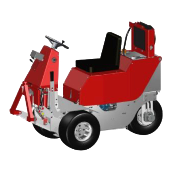
- Page 1 Manoeuvrable. Compact. Powerful.
-
Page 2: Table Of Contents
Table of Contents Table of Contents EC Declaration of Conformity................. 1 Legal information ....................3 Important basic information ..................4 Scope of supply ........................ 4 Conventions ........................5 3.2.1 Symbols and signal words ..............5 3.2.2 Pictogram overview ................6 Marking on the machine .................... - Page 3 Table of Contents Technical specifications ..................18 General technical data CM2 ................. 18 Variant CM2 ......................19 Assembly, first start-up ..................21 Safety ..........................21 Assembly ......................... 21 First start-up ........................21 Product description ....................22 Control ......................... 23 Controls ..........................
-
Page 4: Fig. 28 - Hydraulic Lines
Table of Contents After operation ....................41 17.1 After operation ........................ 41 17.2 Dismantling / Disposal ....................41 Warranty policy ..................... 42 Spare parts list ....................45 19.1 Cover plate ........................45 19.2 Base frame ........................46 19.3 Power lift .......................... -
Page 5: Ec Declaration Of Conformity
EC Declaration of Conformity EC declaration of conformity in accordance with Machinery Directive 2006/42/EC Annex II 1.A The manufacturer / distributor: Westermann GmbH & Co. KG Schützenhof 23 D – 49716 Meppen hereby declares that the following product Product name:... - Page 6 (ISO 12100:2010) The following other technical specifications were applied: Name and address of the person authorised to compile the technical documentation: Westermann GmbH & CO. KG Mr Alfons Westermann Tel.: +49 (0) 5931 | 496 90 0 Schützenhof 23 E-mail: info@westermann-radialbesen.de...
-
Page 7: Legal Information
Right of modification: Westermann GmbH & Co. KG reserves the right to change this document and the subject matter described therein at any time without prior notice, in particular to improve and expand, provided that and as far as contractual agreements or legal requirements do not conflict with this. -
Page 8: Important Basic Information
Important basic information Important basic information Scope of supply The operating manual is part of the working equipment and must be kept accessible in the immediate vicinity of the machine at all times. The operating manual contains important information for safe and effective operation of the machine. -
Page 9: Conventions
Important basic information Conventions 3.2.1 Symbols and signal words Symbol / Signal word Importance Draws your attention to the handling and impact of safety information. Draws your attention to a dangerous situation that will result in serious injury or death if not avoided. Draws your attention to a dangerous situation that can result in serious injury or death if not avoided. -
Page 10: Pictogram Overview
Important basic information 3.2.2 Pictogram overview The safety instructions contained in this operating manual, which can cause danger to persons and the machine if ignored, are specially marked with the following pictograms. Pictogram Importance General warning sign Falling hazard Automatic start-up hazard Opposing rollers hazard (Entanglement risk) Harmful or irritating substances hazard Toxic substances hazard... -
Page 11: Marking On The Machine
Marking on the machine The Cleanmeleon 2 XL has a nameplate that contains all basic data. Components and accessories from suppliers have their own nameplates. Cleanmeleon 2 Type: Serial number: 51. _ _ _ _ 2015 Year of construction: 405 kg... -
Page 12: Safety
Safety Safety Intended use of the machine The Westermann Cleanmeleon 2 is to be used exclusively for the intended use described here. Areas of application of the working machine are the cleaning of slatted floors, sweeping of hard surfaces such as courtyards, paths, car parks, silo plates and stables, clearing snow, breaking up fodder, littering stables or similar work. -
Page 13: Requirements For The Operator
Safety Requirements for the operator Danger due to misuse! Misuse can lead to dangerous situations. Therefore: Refrain from any use beyond the intended use or different use. Strictly comply with all information in this operating manual and, where applicable, the associated documents. ... -
Page 14: Danger Zone
Safety Danger zone Danger while within the danger zone! Being in the danger zone involves risks that unauthorised persons cannot assess. Therefore: Always monitor the danger zone during the work process and ensure that no persons are present there. ... -
Page 15: Foreseeable Misuse | Reasonably Foreseeable Misuse
Safety Foreseeable misuse | Reasonably foreseeable misuse All use deviating from the intended use is considered misuse and is not permitted. These include, for example Transport of humans and animals Use as a climbing aid Use outside the permissible operating limits Behaviour in case of emergency Keep Rescue... -
Page 16: Application
Safety Application The area of application includes all locations worldwide that allow safe use of the machine. Use must be in accordance with the specified intended use. 4.9.1 Local requirements The area of application includes all locations worldwide that allow safe use of the machine. -
Page 17: Obligations Of The Operator
Safety 4.10.1 Obligations of the operator The operator is responsible for ensuring the machine is good working order. The operator must regularly check all safety equipment for functionality and completeness. The operator must ensure that prescribed maintenance is carried out as scheduled. -
Page 18: Personal Responsibility
Safety 4.11 Personal responsibility Basic requirements Only persons who are expected to observe the safety regulations and perform their work reliably may enter the danger zone. Persons whose ability to act is influenced by drugs, alcohol, medicines or the like are not permitted. ... -
Page 19: Observance Of The Operating Manual
Safety 4.12 Observance of the operating manual The operating manual is provided by the manufacturer or supplier of the product in order to provide the user with essential knowledge for the proper and safe use and to point out dangers in handling the machine. Before starting up the machine, the operating manual must be worked through;... -
Page 20: Personal Protection
Safety 4.15 Personal protection The Personal Protective Equipment (PPE) is not included in the scope of delivery. Responsibility for the availability, testing and proper use of PPE therefore lies with the operator. Wear PPE according to the instructions below. ... -
Page 21: Safety Instructions For The Operator/User
Safety instructions for the operator/user Safety instructions for the operator/user Only operate the machine in well-ventilated areas. NEVER use indoors as fuel combustion produces toxic carbon monoxide. If other people are to operate the vehicle, they must be instructed in the operation of the vehicle and read in the operating manual in order to avoid accidents. -
Page 22: Technical Specifications
Technical data Technical specifications General technical data Basic dimensions Value Unit Machine length 1.78 meters [m] Machine width 0.85 meters [m] Machine height 1.26 meters [m] Speed km/h Dry weight kilograms [kg] 1.78 0.85 m Fig. 2 - Dimensions Page 18 of 55... -
Page 23: Variant Cm2 Xl
Technical data Variant CM2 Specifications Engine variant Kubota Z602 Engine type 2-cylinder standing, water-cooled Number of cylinders Combustion system swirl chamber Intake system naturally aspirated 10.8 | 14.7 kW | PS Engine power: Revs. 3200 Fuel diesel Starter electric starter Fig. -
Page 24: Fig. 4 - Inclination
Technical data Tyre pressure front 2.2 | 2.5 min | max Tyre pressure rear 2.2 | 2.5 min | max Hydraulic oil HLP 46 Oil pressure in bar ~ 210 Drive pump ~ 45 l/min (at maximum engine speed) Work hydraulics ~ 24 l/min (at maximum engine speed) -
Page 25: Assembly, First Start-Up
Assembly, first start-up Assembly, first start-up Safety To ensure the safety of man and machine, easy and risk-minimised assembly/handling was taken into consideration during construction. Thus, the handling unit is subject to all applicable DIN EN standards. Operator training and instruction are required and further reduce the safety risk. -
Page 26: Product Description
Product description Product description The Westermann CM2 is designed and implemented for the discerning farmer. It serves as a carrier vehicle for wide-ranging applications. It is possible to sweep hard surfaces such as yards, paths, parking lots, silo slabs and stables, to clear snow, to loosen fodder, to litter stables or to push slatted floors. -
Page 27: Control
Control Control The machine is operated exclusively via the control units on the steering column. The hoist is operated via an integrated valve block with hand lever control. Forward, reverse and handling operations are performed by the operator through a continuously adjustable foot pedal and steering wheel with a steering angle of 88 degrees. -
Page 28: Start-Up
Start-up Start-up 10.1 Checking the engine before start-up The following steps are to be carried out regularly before each use. Checking the engine oil level The oil quantity is checked with a dipstick! Pull dipstick out: Oil quantity must be in the area of the corrugated marking (A)! The oil dipstick is located on the left Fig. -
Page 29: Operation
Operati Operation 11.1 Starting | Stopping the CM2 General description Ignition/Engine ON Status display of the STG-125 engine governor The CM2 has a BARTH STG-125 diesel engine governor. The STG-125 Battery combines the ignition switch and built-in Control/monitoring of the generator voltage. Faults are display lights in one unit. -
Page 30: Running-In Period
Operati 11.2 Running-in period The first 50 hours of operation have a major impact on the performance and service life of the CM2 XL. The following considerations should be taken into account to ensure you enjoy your CM2 for a long time. ... -
Page 31: Short Engine Running Time
Operati 11.3 Short engine running time The oil level must be checked regularly when running the engine for only short periods of time (less than 15 minutes)! When run for short periods, water and petrol can quickly get into the oil and thus, the lubricating effect of the oil is largely lost. -
Page 32: Fig. 13 - Accelerator Pedal
Operati Accelerator The CM2 has an accelerator pedal on the right side of the vehicle. By pressing the pedal forward, the vehicle moves forward. The speed is regulated depending on the pressure intensity on the pedal. The machine is reversed by pulling the pedal Fig. -
Page 33: Attachments
Attachments Attachments The following attachments can be mounted on the CM2 XL. This ensures a variety of uses. Attachments with Accord triangle adapter Fig. 17 - Attachments The attachments themselves must not be changed! The safety regulations in chapter 4 apply. ... -
Page 34: Attachment Of The Equipment
Attachments 12.1 Attachment of the equipment The three-point hoist connects the machine and the attachment making it into one working unit. The position and lifting of the attachment are hydraulically controlled. In addition, the weight and load of the attachment exert pressure on the front axle to improve traction. -
Page 35: Maintenance And Servicing
Maintenance and servicing Maintenance and servicing 13.1 General All maintenance, repair and modification work is to be done on the CM2 only at standstill and when the engine is switched off. The procedure described in the operating manual for stopping the machine must be strictly adhered to. The CM2 is to be checked to ensure it is in a safe condition and secured to prevent it rolling away. - Page 36 Maintenance and servicing Please note during regular maintenance: If necessary, electronically stored instructions for maintenance must be available in paper form during maintenance. For maintenance work involving components from third-party manufacturers, consult the documentation of the third-party manufacturer if necessary. ...
-
Page 37: Table Of Regular Inspections
Maintenance and servicing 13.2 Table of regular servicing Remarks Engine oil Change every 100 hours Engine oil filter Change every 100 hours Air filter Change every 500 hours Radiator Flush out once a year Radiator hose Change every 2 years Fuel filter Change every 500 hours Fuel hose... -
Page 38: Screw Connections
Maintenance and servicing 13.3 Screw connections Check bolts and nuts for the first time after five hours of operation and then tighten them regularly (every 50 hours of operation). All torques M are standard values for metric standard threads according to DIN. -
Page 39: Replacing The V-Belt
Maintenance and servicing 13.5 Replacing the V-belt Engine V-belt When the engine cover is raised, the engine V-belt is on the right in the direction of travel. To replace the belt, the screw connections of the alternator must be loosened. Then swivel the alternator all the way to the middle of the vehicle. -
Page 40: Procedures After Maintenance
Maintenance and servicing 13.8 Procedures after maintenance After completing the maintenance, perform the following steps: Make sure that all previously loosened screw connections are tightened. Ensure all previously removed guards and covers are properly reinstalled. Ensure all tools, materials, and other equipment used have been removed from the work area. -
Page 41: Residual Risks
Residual risks Residual risks Slip hazards Risk of injury due to slip hazards! Defective or improperly fastened hydraulic components can lead to the escape of lubricants in the event of damage. Therefore: Operation may only be carried out by trained personnel. - Page 42 Residual risks Improper operation Risk of injury due to improper operation! Improper operation can lead to personal injury or property damage. Therefore: Operation may only be carried out by trained personnel. Perform all operating steps in accordance with the instructions in this operating manual.
-
Page 43: Storage Conditions
Storage conditions Storage conditions Park the Westermann CM2 in a dry and clean place and secure against unplanned start-up. Fig. 23 - T-handle switch Risk of accident! The CM2 is to be checked to ensure it is in a safe condition and secured to prevent it rolling away. -
Page 44: Troubleshooting
Troubleshoo ting Troubleshooting Fault Cause Remedy No diesel in the tank. Fill the diesel tank. Glow plug defective. Renew glow plug. Air filter dirty Clean/replace air filter Accelerator pedal faulty Check accelerator pedal ... -
Page 45: After Operation
After operation After operation 17.1 After operation After operation of the CM2 XL, it must be stored properly: When storing the machine, the following points must be observed: The CM2 must be placed in such a way that it cannot tip over or fall down. -
Page 46: Warranty Policy
Warranty policy Warranty policy The following policy for the Westermann warranty is valid as of 01.01.2002. When using Westermann products in the consumer goods sector (private use), which were sold through Westermann dealers, the warranty period from the date of sale to the end customer is 2 years. When using... - Page 47 (private | commercial | professional) to Westermann customer service. The warranty period for original Westermann spare parts is 2 years if the installation is certified by a Westermann dealer (for wear parts the restriction under point 3 applies). For warranty claims relating to replacement parts or warranty repairs, we ask you to keep the parts in question for 2 months after receipt of the warranty claim.
- Page 48 Invoicing also occurs if no warranty claim has been received by Westermann Customer Service within 4 weeks. If a Westermann spare part for warranty repairs is not available at short notice (within 2 working days) and you use an original...
-
Page 49: Spare Parts List
Spare parts list Spare parts list 19.1 Cover plate Fig. 25 - Cover Pos. Item no. Description Amount Engine cover LA-00-00457 LA-00-00458 Cover sheet PE-00-00019 Cover holder CM2 seat KT-00-00419 Page 45 of 55... -
Page 50: Base Frame
Spare parts list 19.2 Base frame Fig. 26 - Base frame Pos. Item no. Description Amount Triangle KT-00-00004 LA-00-00010 Lower link Chassis tub LA-00-00473 LA-00-00470 Front crosspiece KT-00-00035 Hydraulic cylinders Top link KT-00-00011 LA-00-00469 Angular plate connections Plug-in coupling sleeve HY-00-00130 Plug-in coupling HY-00-00131... -
Page 51: Power Lift
Spare parts list 19.3 Power lift Fig. 27 - Power lifter Pos. Item no. Description Amount Triangle KT-00-00004 Lower link LA-00-00010 Top link KT-00-00011 Hydraulic cylinders KT-00-00035 MBG_Hydr-Hose_Leak-Work-hydr. MBG_HY. pipe Page 47 of 55... -
Page 52: Hydraulic Lines
Spare parts list 19.5 Hydraulic lines Fig. 28 - Hydraulic lines Pos. Item no. Description Feature Amount MBG_Hydr-Hose_A-Valv_Hoist-piston (pink) HYS-00-00062 G-Hydr-Hose_B-Valve_Hoist-bar HYS-00-00066 MBG_Hydr-Hose_Filter_T-valve D blue HYS-00-00073 MBG_Hydr-Hose_B-Ventil_Work-Hydr_low yellow HYS-00-00065 purple HYS-00-00064 MBG_Hydr-Hose_A-Valve-Work-hydr-upper HYS-00-00063 MBG_Hydr-Hose_P valve/pump MBG_Hydr-Hose_D-Drivepump_Cooler-in orange HYS-00-00070 MBG_Hydr-Hose_Ball-valve-2 D green HYS-00-00074 HYS-00-00075 MBG_Hydr-Hose_Ball-valve-1... -
Page 53: Rear Wheel Bearing
Spare parts list 19.6 Rear wheel bearing Fig. 29 - Rear wheel bearing Pos. Item no. Description Amount Orbital engine rear MO-00-00023 HYS-00-00080 MBG_Hydr-Hose_Drive-motor-bk LA-00-00464 Rear wheel swingarm Sprocket LA-00-00465 Thrust bearings KT-00-00113 Page 49 of 55... -
Page 54: Foot Pedal
Spare parts list 19.7 Foot pedal Fig. 30 - Foot pedal Pos. Item no. Description Amount Accelerator LA-00-00454 Accelerator shaft DR-00-00095 Accelerator rod VMBG-00-00012 Adjustment ring 20-32-14 KT-00-00167 Page 50 of 55... -
Page 55: Parts / Components
Spare parts list 19.8 Parts / components Fig. 31 - Main components Pos. Item no. Description Amount Work pump KT-00-00618 Flange coupling KT-00-00611 / 615 MO-00-00022 Diesel engine KT-00-00611 Orbital engine rear MO-00-00023 MO-00-00024 Orbital engine front Combination tank SB-00-00029 KT-00-00002 Air filter KIT KT-00-00016... -
Page 56: Steering Console
Spare parts list 19.9 Steering console Fig. 32 - Steering console Pos. Item no. Description Amount Steering wheel CM2 KT-00-00297 Steering rod - upper DR-00-00093 Steering stub DR-00-00102 Steering rod - lower DR-00-00096 Gear wheel m2; z 50 LA-00-00450 Sprocket 06 B-1 (z=16) HT-00-0046 Expansion tank KT-00-00042... -
Page 57: Plans And Other Information
Plans and other information Plans and other information 20.1 Hydraulic plan Page 53 of 55... -
Page 58: Engine Control Circuit Diagram
Plans and other information 20.2 Engine control circuit diagram Page 54 of 55... -
Page 59: List Of Figures
List of figures List of figures Fig. 1 - Danger zone ..................... 10 Fig. 2 - Dimensions ...................... 18 Fig. 3 - Engine dimensions ................... 19 Fig. 4 - Inclination ......................20 Fig. 5 - Controls ......................23 Fig. 6 - Oil level ......................24 Fig.
Need help?
Do you have a question about the Cleanmeleon 2 XL and is the answer not in the manual?
Questions and answers