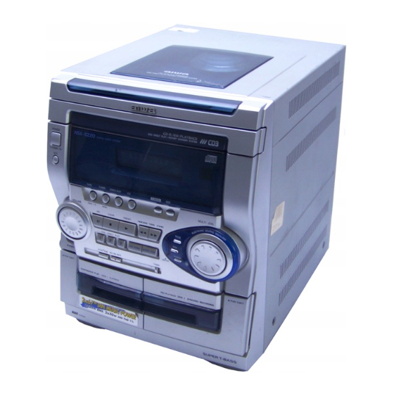
Aiwa NSX-DR1 Service Manual
Compact disc stereo systems
Hide thumbs
Also See for NSX-DR1:
- Service manual (3 pages) ,
- Service manual (29 pages) ,
- Service manual (34 pages)
Table of Contents
Advertisement
Quick Links
All manuals and user guides at all-guides.com
SERVICE MANUAL
COMPACT DISC
STEREO SYSTEM
SYSTEM
NSX-DR1
NSX-SZ20
• This Service Manual is the "Revision Publishing" and replaces "Simple Manual"
NSX-DR1(EZ), (S/M Code No. 09-004-423-4T4).
• If requiring information about the CD mechanism, see Service Manual
of AZG-1, (S/M Code No. 09-001-335-3N8).
NSX-DR1
NSX-SZ20
BASIC TAPE MECHANISM : ZZM-3 PR1NM
BASIC CD MECHANISM : AZG-1 ZD3RDM
CD
SPEAKER
CASSEIVER
CX-NDR1
SX-NSZ20
CX-NSZ20
SX-NSZ22
S/M Code No. 09-007-423-4R4
EZ
V
REMOTE
CONTROLLER
RC-ZAS02
Advertisement
Table of Contents

Related Manuals for Aiwa NSX-DR1


Summary of Contents for Aiwa NSX-DR1
- Page 1 CX-NSZ20 SX-NSZ22 • This Service Manual is the “Revision Publishing” and replaces “Simple Manual” NSX-DR1(EZ), (S/M Code No. 09-004-423-4T4). • If requiring information about the CD mechanism, see Service Manual of AZG-1, (S/M Code No. 09-001-335-3N8). S/M Code No. 09-007-423-4R4...
-
Page 2: Specifications
All manuals and user guides at all-guides.com SPECIFICATIONS <FM tuner section> <Compact disc player section> Tuning range Laser Semiconductor laser (λ =780 nm) 87.5 MHz to 108 MHz D-A converter 1 bit dual Signal-to-noise ratio 85 dB (1 kHz, 0 dB) FM1 (OIRT) Harmonic distortion 0.05 % (1 kHz, 0 dB) -
Page 3: Protection Of Eyes From Laser Beam During Servicing
All manuals and user guides at all-guides.com PROTECTION OF EYES FROM LASER BEAM DURING SERVICING This set employs laser. Therefore, be sure to follow carefully CAUTION the instructions below when servicing. Use of controls or adjustments or performance of proce- dures other than those specified herin may result in WARNING!! hazardous radiation exposure. -
Page 4: Note On Before Starting Repair
All manuals and user guides at all-guides.com NOTE ON BEFORE STARTING REPAIR 1. Forced discharge of electrolytic capacitor of power supply block When repair is going to be attempted in the set that uses relay circuit in the power supply block, electric potential is kept charged across the electrolytic capacitors (C101, 102) even though AC power cord is removed. - Page 5 All manuals and user guides at all-guides.com In such a case, check also if the POWER AMPLIFIER circuit or power supply circuit has any abnormalities or not. 2-2. Regarding reset There are cases that the machine does not work correctly because the MICROCOMPUTER is not reset even though the AC power cord is re-inserted, or the software reset (pressing the STOP key + POWER key) is performed.
-
Page 6: Electrical Main Parts List
All manuals and user guides at all-guides.com ELECTRICAL MAIN PARTS LIST REF. NO. PART NO. KANRI DESCRIPTION REF. NO. PART NO. KANRI DESCRIPTION 87-010-247-080 CAP, ELECT 100-50V 87-010-380-080 CAP, ELECT 47-16V M 11L 87-A21-397-010 IC,STK490-070 87-010-381-080 CAP, ELECT 330-16V 87-A21-419-040 IC,NJM14558MD-TE2 87-010-197-080 CAP, CHIP 0.01-25 K B... - Page 7 All manuals and user guides at all-guides.com REF. NO. PART NO. KANRI DESCRIPTION REF. NO. PART NO. KANRI DESCRIPTION C452 87-010-382-080 CAP, ELECT 22-25V C831 87-010-406-080 CAP, ELECT 22-50 M SME<EZ> C453 87-010-183-080 C-CAP,S 2700P-50 B C842 87-010-197-080 CAP, CHIP 0.01-25 K B C454 87-010-183-080 C-CAP,S 2700P-50 B...
- Page 8 All manuals and user guides at all-guides.com REF. NO. PART NO. KANRI DESCRIPTION REF. NO. PART NO. KANRI DESCRIPTION R143 87-A00-440-050 RES,220-1/2W J RP FC104 88-911-101-110 FF-CABLE,11P 1.25 R144 87-A00-440-050 RES,220-1/2W J RP FC731 88-913-301-110 FF-CABLE,13P-1.25 R145 87-A00-440-050 RES,220-1/2W J RP FL901 8A-NF9-605-010 FL,HNA-10SS12...
-
Page 9: Chip Resistor Part Code
All manuals and user guides at all-guides.com CHIP RESISTOR PART CODE Chip Resistor Part Coding Figure Resistor Code Value of resistor Chip resistor Dimensions (mm) Wattage Type Tolerance Symbol Resistor Code Form 1/16W 1005 0.35 1/16W 1608 0.45 1/10W 2125 1.25 0.45 1/8W... - Page 10 All manuals and user guides at all-guides.com FL (HNA-10SS12) GRID ASSIGNMENT AND ANODE CONNECTION GRID ASSIGNMENT ANODE CONNECTION – 10 –...
-
Page 11: Wiring - 1 (Main)
All manuals and user guides at all-guides.com WIRING – 1 (MAIN)<EZ> – –... -
Page 12: Wiring - 2 (Main)
All manuals and user guides at all-guides.com WIRING – 2 (MAIN)<V> – –... - Page 13 All manuals and user guides at all-guides.com SCHEMATIC DIAGRAM – 1 (MAIN 1 / 2 : AMP) – –...
- Page 14 All manuals and user guides at all-guides.com SCHEMATIC DIAGRAM – 2 (MAIN 2 / 2 : TUNER)<EZ> – –...
- Page 15 All manuals and user guides at all-guides.com SCHEMATIC DIAGRAM – 3 (MAIN 2 / 2 : TUNER)<V> – –...
-
Page 16: Wiring - 3 (Front)
All manuals and user guides at all-guides.com WIRING – 3 (FRONT) – –... -
Page 17: Schematic Diagram - 4 (Front)
All manuals and user guides at all-guides.com SCHEMATIC DIAGRAM – 4 (FRONT) – –... - Page 18 All manuals and user guides at all-guides.com WIRING – 4 (PT) – 18 –...
-
Page 19: Schematic Diagram - 5 (Pt)
All manuals and user guides at all-guides.com SCHEMATIC DIAGRAM – 5 (PT) – 19 –... -
Page 20: Wiring - 5 (Deck)
All manuals and user guides at all-guides.com WIRING – 5 (DECK) FROM B FRONT C. B CN104 D DECK C . B FC104 – –... - Page 21 All manuals and user guides at all-guides.com – 21 –...
-
Page 22: Ic Block Diagram
All manuals and user guides at all-guides.com IC BLOCK DIAGRAM – 22 –... - Page 23 All manuals and user guides at all-guides.com – 23 –...
- Page 24 All manuals and user guides at all-guides.com IC DESCRIPTION µ PD780226GF-014-3BA / 015-3BA Pin Name Description Pin No. O-MOTOR DECK MOTOR ON/OFF output. O-SOL1 DECK1 solenoid output. O-SOL2 DECK2 solenoid output. – Not connected. – Not connected. O-SET_LED SET LED ON/OFF output. O-CLEAR_LED CLEAR LED ON/OFF output.
- Page 25 All manuals and user guides at all-guides.com Pin Name Description Pin No. I-SPEANA_L A/D L-input for spectrum analyser level display. I-SPEANA_R A/D R-input for spectrum analyser level display. I-KEY1 Key1 input. I-KEY2 Key2 input. I-KEY3 Key3 input. I-TU_SIG Tuner signal input. AVSS –...
- Page 26 All manuals and user guides at all-guides.com ADJUSTMENT <TUNER / DECK / FRONT> < TUNER SECTION > < DECK SECTION > 1. Clock frequency Check 10. Tape Speed Adjustment (DECK 2) Settings : • Test point : TP2 (CLK) Settings : • Test tape : TTA–100 Method : Set to AM(MW) 1602kHz and check that the test point •...
- Page 27 All manuals and user guides at all-guides.com MECHANICAL EXPLODED VIEW 1 / 1 AZG-1 ZD3RDM P.C.B WIRE,BINDER HT-SINK FL901 P.C.B P.C.B CHAS,MAIN ZZM-3 PR1NM PLATE,EARTH MECH – 27 –...
-
Page 28: Mechanical Parts List
F-CABLE,9P 2.5 480MM 5 8A-NF8-207-010 SPR-T,EJECT 1 34 88-913-301-110 FF-CABLE,13P-1.25 6 8A-NF8-208-010 SPR-T,EJECT 2 35 88-911-101-110 FF-CABLE,11P 1.25 7 87-CE3-023-010 BADGE,AIWA 30N SILV 36 87-NF4-216-010 HLDR,LOCK 1 8 8A-NF9-018-010 KNOB,RTRY JOG 37 86-NF9-224-010 SPR-C,LOCK 9 8A-NF8-209-010 OIL-DMPR,120 38 82-NF5-229-010 PLATE,LOCK... - Page 29 All manuals and user guides at all-guides.com TAPE MECHANISM EXPLODED VIEW 1 / 1 TERMINAL,LB1 TERMINAL, IC, EW732 IC, EW732 P.C.B – 29 –...
-
Page 30: Tape Mechanism Parts List
All manuals and user guides at all-guides.com TAPE MECHANISM PARTS LIST 1 / 1 REF. NO. PART NO. KANRI DESCRIPTION REF. NO. PART NO. KANRI DESCRIPTION 8Z-ZM3-227-010 0E BELT,MAIN M3 8Z-ZM3-233-010 0E SPR-T,BRG M3 8Z-ZM3-235-010 0E BELT,MAIN L 84-ZM2-227-310 0E SPR-C,AZIMUTH 8Z-ZM1-235-010 0E PULLEY,MOT 87-A90-403-110 1B HEAD,RPH MS15R 87-045-347-010 1H MOT,SHU2L 70... - Page 31 All manuals and user guides at all-guides.com SPEAKER DISASSEMBLY INSTRUCTIONS Type.1 Type.4 Insert a flat-bladed screwdriver into the position indicated by the TOOLS arrows and remove the panel. Remove the screws of each speaker Plastic head hammer unit and then remove the speaker units. (() flat head screwdriver Cut chisel How to Remove the PANEL, FR...
-
Page 32: Accessories / Package List
All manuals and user guides at all-guides.com SPEAKER PARTS LIST SX-NSZ20 (YSL,YSC9,YSY1,YSY2), SX-NSZ22 (YJSC,YJSC9) REF. NO. PART NO. KANRI DESCRIPTION 1 8A-NSK-001-010 PANEL,FR 2 8A-NSK-003-010 GRILLE,FRAME ASSY 3 8A-NSK-007-010 PROTECTOR,TWA 4 8A-NSK-602-010 SPKR,W 140<EXCEPT YJSC> 4 8A-NSJ-602-010 SPKR,W 130<YJSC> 5 88-NS5-605-010 SPKR,T 60<EXCEPT YJSC>... - Page 33 All manuals and user guides at all-guides.com 2–11, IKENOHATA 1–CHOME, TAITO-KU, TOKYO 110, JAPAN TEL:03 (3827) 3111 9820543 0251431 Printed in Singapore...
Need help?
Do you have a question about the NSX-DR1 and is the answer not in the manual?
Questions and answers