Table of Contents
Advertisement
Quick Links
Advertisement
Table of Contents
Troubleshooting

Related Manuals for Metallisation MK 73


Summary of Contents for Metallisation MK 73
- Page 1 ssue: 21/11-11 Page 1 of 64...
- Page 2 In particular, refer to the Safety Warnings / Risk Assessments in Section 1. Under no circumstances should any modifications be made to the equipment without prior written approval from Metallisation. Issue: 07-10-2013 Page 2 of 64...
- Page 3 SPECIFICATIONS The Metallisation MK73 is an Oxygen – Propane fuelled flame spray system typically used for the application of anti-corrosion coatings. The following specifications are for a standard Pistol system with 1/4" hoses. Weight - Complete, excluding supply hoses 2.27Kg (5lb)
-
Page 4: Table Of Contents
CONTENTS SECTION 2 SAFETY PRECAUTIONS & RISK ASSESSMENTS ................6 Safety Precautions ............................7 Equipment Dos and Don’ts ........................7 1.1.1 1.1.2 Leak Test Procedures ..........................8 1.1.3 Flashback ..............................9 Risk Assessment ............................10 Key Hazards ............................. 11 1.3.1 Noise .............................. - Page 5 The Gas Head & Main Valve ........................32 4.5.1 Removal & Dismantling .......................... 32 4.5.2 Gas Head & Valve Re-Assembly ......................33 The Drive Box ............................34 4.6.1 Dismantling the Wire Drive Assembly ....................35 4.6.2 Dismantling the Air Shield Valve ......................36 4.6.3 Dismantling the Speed Control .......................
-
Page 6: Safety Precautions & Risk Assessments
SECTION 1 SAFETY PRECAUTIONS & RISK ASSESSMENTS Safety Precautions 1.1.1 Equipment Dos & Don’ts 1.1.2 Leak Test Procedure 1.1.3 Flashback Risk Assessments Key Hazards 1.3.1 Noise 1.3.2 Flame 1.3.3 Particles 1.3.4 Mechanical Hazards 1.3.5 Fume & Dust 1.3.6 Summary Page 6 of 64... -
Page 7: Safety Precautions
Careful consideration should be taken when positioning this equipment. It is the responsibility of the user to ensure that all appropriate measures are in place for safe operation, before the equipment is used. Metallisation will be pleased to assist and advise as appropriate. -
Page 8: Leak Test Procedures
1.1.2 Leak Test Procedures Leak Test Procedure - to be carried out before the pistol is used: Make sure all the hoses are connected correctly and gauges are in good working order. Fit the leak test nozzle 1260 on to the pistol. ... -
Page 9: Flashback
Under these circumstances, use a leak detection spray or liquid to identify, then rectify the leak before using the Pistol. If there is no movement of pressure gauges, then there is no identifiable leak and the pistol is safe to use. NB: Leak Test Information is based on the assumption that all pressure gauges are in good working order, with any visible defects having already been rectified e.g. -
Page 10: Risk Assessment
Risk Assessment Prior to commencing work with Thermal Spray equipment, a Risk Assessment should be carried out on the equipment and the way in which that equipment is to be used. The Risk Assessment should identify the hazards associated with the work and also the control measures required. -
Page 11: Key Hazards
Key Hazards In this section the key hazards associated with Thermal Spraying are described. It includes a brief description of the hazards and their possible consequences. In any Risk Assessment for a Thermal Spray Process, a consideration of all relevant hazards will need to be included. -
Page 12: Mechanical Hazards
1.3.4 Mechanical Hazards If equipment has been installed to manipulate the component and/or spray gun, it is important that it is designed to protect the operator from mechanical hazards. It is possible for the operator to be struck by a moving table or manipulator, to be crushed against the wall of the booth, or to become entangled in rotating machinery. - Page 13 Aluminium Long term inhalation of aluminium powder or aluminium oxide may cause scarring of the lungs. Aluminium powder can form explosive mixtures with air. Chromium Prolonged exposure to chromium metal dust may give rise to lung fibrosis. It is highly toxic. Chromium oxide and chrome carbide feedstock are both chromium (III), the less toxic form of chromium.
-
Page 14: Summary
1.3.6 Summary Below is an approximate rating of the hazards in typical circumstances while using the MK73 Flame Spray System. It must be stressed that the hazard ratings may change in individual circumstances. An example of this would be the rating for toxic consumables. This would relate directly to the consumable in use. -
Page 15: The Equipment
SECTION 2 THE EQUIPMENT Introduction to the MK73 Breakdown 2.2.1 The Pistol 2.2.2 Flowmeters 2.2.3 Air Filtration & Regulation Unit 2.2.4 Pressure Regulators & Flashback Arrestors 2.2.5 Freestanding Flamespray Control Board 2.2.6 Supplies Packages Page 15 of 64... -
Page 16: Introduction To The Mk73
Zinc, Aluminium and other similar alloys. It is also suitable for use with some of the Engineering Wires e.g. Steels and Bronzes. The MK 73 boasts the following features: A rugged construction, which is designed to meet all the requirements of the practical metal sprayer. -
Page 17: Breakdown
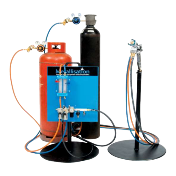
Breakdown Here are the typical system configurations for the Metallisation MK73 Flame Spray system: 2, 3 & 4 6m standard 3m standard Maximum 20m from cylinders to pistol with 1/4” ‘short’ hoses Maximum 40m from cylinders to pistol with 3/8” ‘long’ hoses... -
Page 18: The Pistol
2.2.1 The Pistol Pistols vary dependant on the wire size that is to be sprayed. The Pistol shown is for a standard 3/16” System. The table below this illustration gives the variant pistol part numbers for the relevant wire size that is used: Nozzle (Without Spreader) Accurately profiled and sleeved with stainless steel insert. -
Page 19: Flowmeter
Only high quality light lubricating oil such as Metallisation Lubricating Oil should be used. 2.2.4 Pressure Regulators & Flashback Arrestors The pistol should be used with Metallisation high flow two stage regulators, which are supplied with the correct fittings for connection to the MK73. -
Page 20: Supplies Packages
2.2.6 Supplies Packages Metallisation can supply standard and non-standard hose sizes, to suit the appropriate application. Listed below are the part numbers for ‘short’ hose configurations (1/4” hoses): Supplies from cylinders to flowmeters Supplies from flowmeters to Pistol Propane Hose... - Page 21 Listed below are the part numbers for ‘long’ hose configurations (3/8” hoses): SUP73L-FLOW 20M SUP73L-PISTOL 10M Part Number 20m supplies package 10m supplies package Consisting: 21525/20 Propane Hose Consisting: 21523 Propane Hose 21526/20 Oxygen Hose 21524 Oxygen Hose 21522 Nozzle Air Hose 21504/10 Motor Air Hose Part Number SUP73L-FLOW 30M...
-
Page 22: Operating The Equipment
SECTION 3 OPERATING THE EQUIPMENT Preparing the System Starting to Spray Spraying Extinguishing the Pistol Emergency Shut-Off Valve Page 22 of 64... -
Page 23: Preparing The System
Preparing the System The following pistol preparation should be carried out prior to using the pistol: Remove all packaging and ensure that the equipment has suffered no damage whilst in transit. Ensure that all hoses, fittings and components are clean and free from damage. The hoses are colour coded to avoid confusion: HOSE SIZE HOSE SIZE... - Page 24 Check that the Nozzle Shell, Screwed Insert, Air Nipple, Mixing Block and Air Motor are correctly fitted. Ensure that all necessary ‘O’ Rings are present, in good condition and correctly fitted. A full listing of ‘O’ Ring part numbers can be found in Section 7. Use the following procedure to begin using the pistol: ...
-
Page 25: Spraying
Spraying Follow the below procedure to commence spraying: Once lit, if fitted adjust the spreader, in the direction shown below to give the desired direction of the spread. Operator Point of View NOTE: There is a position of the spreader where the air to the spreader jet is cut off. If the spreader is not required, rotate the spreader until it shuts off. -
Page 26: Extinguishing The Pistol
Extinguishing the Pistol When finished spraying, follow the procedure below to correctly extinguish the pistol: At the end of the spraying session, to extinguish the flame turn the pistol valve to the OFF position (180° anti-clockwise in a single smooth movement) but hold the wire feed trigger for approximately 1 second longer. -
Page 27: Maintenance & Repair
SECTION 4 MAINTENANCE & REPAIR Recommended Spares Routine Maintenance Disconnecting the Pistol The Nozzle Assembly 4.4.1 Removal & Dismantling 4.3.2 Nozzle Re-Assembly The Gas Head & Main Valve 4.5.1 Removal & Dismantling 4.5.2 Gas Head & Valve Re-Assembly The Drive Box 4.6.1 Dismantling the Wire Drive Assembly 4.6.2 Dismantling the Air Shield Valve 4.6.3 Dismantling the Speed Control... -
Page 28: Recommended Spares
Recommended Spares The recommended spares for the MK73 Flamespray system are available as a complete pack. Part Number: GAS-SSP - MK61 / MK73 Standard Spares Pack for Gas Systems. This comprises of the following parts: PART NO. DESCRIPTION QUANTITY ‘O’ Ring 1007 ‘O’... -
Page 29: Disconnecting The Pistol
Check hose connection and hose condition and replace any connection or hose as necessary. As part of the routine maintenance, the system should also be leak tested at least every time the system is assembled and once per week. (See Leak Test Procedure - Section 1.1.2). Disconnecting the Pistol Follow the below procedure to disconnect the pistol: ... -
Page 30: The Nozzle Assembly
The Nozzle Assembly 4.4.1 Removal & Dismantling 6x’O’ Ring DIAG 1. Referring to DIAG 1, use the following procedure to dismantle the WHEN & WHY? Nozzle Assembly, when necessary: Nozzle Assembly should only be dismantled If fitted, pull off the Spreader Ring (A) and discard any damaged ‘O’ when absolutely Rings (M) or cork seals (N). -
Page 31: Nozzle Re-Assembly
4.4.2 Nozzle Re-Assembly Still referring to DIAG 1 Use the procedure below to re-assemble the Nozzle: Fit the correct ‘O’ Rings (K & L) and fit the Front Wire Guide (I), steel insert first, into the back of the Gas Head (F) and re-fit the Gas Head to the Drive Box using the Gas Head Fixing Screws (J). -
Page 32: The Gas Head & Main Valve
The Gas Head & Main Valve 4.5.1 Removal & Dismantling G (2x Screw) U (3x Seals) (3x Plungers) E (2x Screw) (3x Valve Diaphragms) DIAG 5 DIAG 6 WHEN & WHY? Referring to DIAG 5 and DIAG 6, use the following procedure to dismantle the Gas Head and Main Valve Assembly, when necessary: The Gas Head and Main Valve... -
Page 33: Gas Head & Valve Re-Assembly
Using a suitable drift drive out the long 3/32” Cam Lever Dowel (Q) at the end of the Cam Spindle Housing furthest from the lever. Withdraw the Cam Spindle (R). Unscrew the Retaining Screws (W) in the base of the Gas Head and retain these. Remove and discard the two Filters (Y). -
Page 34: The Drive Box
The Drive Box SUB A SUB A SUB B SUB D FITS IN HERE SUB C DIAG 8 SUB C SUB B Page 34 of 64... -
Page 35: Dismantling The Wire Drive Assembly
4.6.1 Dismantling the Wire Drive Assembly WHEN & WHY? The Wire Drive Assembly should only be dismantled when it is absolutely necessary. For example: There is excessive play in Wire Rollers. The Wire Rollers cannot be opened. The Wire Feed Lever spins through 360°... -
Page 36: Dismantling The Air Shield Valve
4.6.2 Dismantling the Air Shield Valve WHEN & WHY? The Air Shield Valve should only be dismantled when it is absolutely necessary. For example: Wire melts back onto the Nozzle. DIAG 9 Referring to DIAG 9 above: Screw out the Valve Screw (G). ... -
Page 37: Dismantling The Speed Control
4.6.3 Dismantling the Speed Control WHEN & WHY? The Speed Control should only be dismantled when it is absolutely necessary. For example: Damage is known to have occurred. DIAG 10. Referring to DIAG 10: Remove the Exhaust Plug (D5). ... -
Page 38: Re-Assembling The Air Shield Valve
4.6.5 Re-Assembling the Air Shield Valve Referring to DIAG 11 and 12 (below): Locate the Diaphragm (Large) (A). Insert into the Valve Cavity in the Pistol. Place the Diaphragm Disc (C), plunger first into the Valve Retainer (B) and then into the Valve Cavity, disc side first. - Page 39 Register the Socket Set Screws (E) with the shaft dimples and tighten to hold the shafts steady. Check for free rotation. It is recommended that locking fluid is used on these screws. Fit the inner to the outer Yoke Assembly. ...
- Page 40 Spanner. Half fill the body cavity with Metallisation grease (P/N: 21173) and fit the Feed Roll Gasket (H) over the Yoke Support collars (I). NB: Ensure that it is correctly located in the grooves on the top of the yokes ...
-
Page 41: The Drive Motor
Fit new ‘O’ Rings (C & D) to both the inner and outer grooves of the Seal Housing (B). Lightly grease using Metallisation Grease (part no. 21173) and slide the Seal Housing (B) onto the boss of the Bevel Pinion (E). -
Page 42: Feed Roller Tension
Feed Roller Tension 4.8.1 Checking Feed Roller Tension When the pistol is fully assembled, connect an airline to the drive motor. Pass a length of the wire to be sprayed through the pistol and close the drive rollers. ... -
Page 43: Fault Finding
SECTION 5 FAULT FINDING Troubleshooting 5.1.2 Flowmeter Troubleshooting Page 43 of 64... -
Page 44: Troubleshooting
Troubleshooting When incurring any problem with the Flamespray process, it is necessary to first check that the correct consumable parts i.e. Nozzle Assembly, are fitted and in good condition. Spraying parameters should also be checked as per Section 8: Flowmeter Settings. If the problem still persists, then consult the below tables. - Page 45 Troubleshooting continued: PROBLEM CAUSE REMEDY Insufficient air pressure Check supply and re-adjust regulator Air Nipple dirty or damaged Clean or replace Air Nipple Wire feeding too fast Slow down wire speed The coating is too coarse Remove and re-fit Air Nipple, checking that it is Air nipple jammed in lighting position free to move on the Nozzle Remove and clean, or replace Nozzle...
-
Page 46: Flowmeter Troubleshooting
5.1.2 Flowmeter Troubleshooting: PROBLEM POSSIBLE CAUSES REMEDY Restriction in Nozzle Clean Nozzle with special OXYGEN FLOAT - NORMAL Metallisation cleaners GAS FLOAT - LOW Gas hole in Mixing Block restricted Clear or replace Mixing Block Middle ‘O’ Ring at rear of OXYGEN FLOAT - HIGH Replace ‘O’... - Page 47 Note (b) This type of reading, with both floats equally low and pressures correct can be due to: Restricted nozzle holes or undersized air nipple or dirty air nipple or too much air pressure. Restricted mixing block holes. ...
-
Page 48: Wire Dispensing
SECTION 6 WIRE DISPENSING Wire Swift 6.1.1 Operating Instructions 6.1.2 Wire Straightener Page 48 of 64... -
Page 49: Wire Swift
Wire Swift The Metallisation Wire Swift is specifically designed to dispense wires for flame spraying. It provides a flexible and easy to use wire dispensing system. The Wire Swift boasts the following features: Wire tripod base giving stability and strength. -
Page 50: Wire Straightener
After spraying a small amount of wire, adjust the brake knob to allow some drag so there is no over-run when the pistol is stopped. 6.1.2 Wire Straightener Some wires may require straightening. The Metallisation Wire Swift incorporates a Wire Straightener. See DIAG 21 (below): DIAG 21 Operating the Wire Swift: ... -
Page 51: Illustrated Parts List
SECTION 7 ILLUSTRATED PARTS LIST Gas Head & Spreader Nozzle Diaphragm Valve Power Unit / Drive Motor Wire Drive Unit & Feed Control Page 51 of 64... -
Page 52: Gas Head & Spreader Nozzle
Gas Head & Spreader Nozzle 1007 1008 10073S 1017 ‘O’ Ring Set Non Spreader Air Cover 1066 Mixing Block Front Wire Guide 1250 / 1250-73 1258 1065 1029 6021 1027 1025 1003A 1063 1028 1254 1253 1024 Spreader Ring Screwed Insert Nozzle Shell Air Nipple Common Parts Tables:... - Page 53 Variations Tables: The tables that follow list the numbers for the parts of the Nozzle Assembly that are dependent upon the wire size and pistol variant used. Refer to the Nozzle Selection Chart – Section 8.2 Nozzle Shell Variations Screwed Insert Variations 1/8”...
-
Page 54: Diaphragm Valve
Diaphragm Valve 1211 1210 6526 1206 1209 1207 1042 1213 1203 1039 1028 1204 1044 1212 1036 1040/41 1031 **1201 / 1220 **1033/35 / 28077 **1216 / 1223 **1217 / 1222 1038 **1218 / 1221 Parts Tables: PART NO. DESCRIPTION PART NO. -
Page 55: Power Unit / Drive Motor
Power Unit / Drive Motor 4550 4505 4538 4504 4534 4852/4853 28077 Parts Table: PART NO. DESCRIPTION 4504 Bevel Pinion 4505 Seal Housing 4534 1/4" Connector R/H Thread ’O’ Ring 4538 ’O’ Ring 4550 4852 Motor 4000 Rpm 4853 Motor 2500 Rpm 28077 Soft Copper Washer Page 55 of 64... -
Page 56: Wire Drive Unit & Feed Control
Wire Drive Unit & Feed Control SUB A SUB A SUB B 4523 4527 4526 SUB D AT 4511 REAR 1052 4517 Rear Wire Guide Assy 1051 SUB E FITS HERE 4501 SUB C SUB B SUB C 4502 4503 4533 4506 4531... - Page 57 Common Parts Table: PART NO. DESCRIPTION PART NO. DESCRIPTION Socket Set Screw 4506 Bearing Housing Socket Head Screw 4508 Retaining Screw Bearing 4510 Bearing Cap Cover Screw 4511 Feed Roll Cover Lock Screw 4512 Valve Retainer Yoke Support Valve Cap 4513 ‘O’...
-
Page 58: Information Tables
SECTION 8 INFORMATION TABLES Flowmeter Settings Nozzle Selection Chart Page 58 of 64... -
Page 59: Flowmeter Settings
20 (1.4) 30 (2.1) The figures shown assume the use of Metallisation Flashback Arrestors. If these are not used, the oxygen pressures should be adjusted to suit. Since the oxygen pressure is varied to achieve the desired float positions the oxygen pressures given are approximate. -
Page 60: Nozzle Selection Chart
Nozzle Selection Chart FRONT REAR WIRE SPRAY MIXING NOZZLE WIRE NOZZLE WIRE DIAMETER MODE BLOCK INSERT NIPPLE GUIDE GUIDE 4.76mm Stop/Start 1271 1429/3/16” 1288/SHELL 1288I 1302 1256 (3/16”) 4.76mm Fast 1271 4509F 1281 1302 1256 (3/16”) 4.0mm Stop/Start 1271 1429/40 1288/SHELL 1289I 1302... - Page 61 Notes Page 61 of 64...
- Page 62 Page 62 of 64...
- Page 63 Page 63 of 64...
- Page 64 The information in this manual was correct at the time of publication; Metallisation disclaims liability for any inaccuracies or omissions that may have occurred. Periodically, changes are made to the information herein, and Metallisation reserve the right to make improvements and/or changes to the products described in this Page 64 of 64 publication at any time without prior notice.
Need help?
Do you have a question about the MK 73 and is the answer not in the manual?
Questions and answers